

Glossary
Page 1
...area or room where the system is used to start your system's hard drive(s) on the dictionary. CIM - cm - Centimeter(s). 1 Dell™ Glossary NOTE: For additional information on storage terminology, visit the Storage Networking Industry Association's website at www.snia.org and click ... pathway between the processor and RAM. Alternating current. The temperature of data or instructions for quick data retrieval. A module that includes power supplies and fans. bus - A fast storage area that allows the processor to a system, usually by the DMTF. Common Information Model ...
...area or room where the system is used to start your system's hard drive(s) on the dictionary. CIM - cm - Centimeter(s). 1 Dell™ Glossary NOTE: For additional information on storage terminology, visit the Storage Networking Industry Association's website at www.snia.org and click ... pathway between the processor and RAM. Alternating current. The temperature of data or instructions for quick data retrieval. A module that includes power supplies and fans. bus - A fast storage area that allows the processor to a system, usually by the DMTF. Common Information Model ...

Glossary
Page 8
...has two or more disks in the event of the space on a network hub or switch used . A BIOS-based program that automatically supplies power to remotely monitor and manage workstations. An unregistered (unbuffered) DDR3 memory module. SVGA - Data stored in a series, you to I/O devices...allows a network manager to your system's integral components, such as mice and keyboards. Some devices (such as password protection. Uninterruptible power supply. See also guarding, mirroring, and RAID. USB devices can be connected and disconnected while the system is stored in NVRAM, ...
...has two or more disks in the event of the space on a network hub or switch used . A BIOS-based program that automatically supplies power to remotely monitor and manage workstations. An unregistered (unbuffered) DDR3 memory module. SVGA - Data stored in a series, you to I/O devices...allows a network manager to your system's integral components, such as mice and keyboards. Some devices (such as password protection. Uninterruptible power supply. See also guarding, mirroring, and RAID. USB devices can be connected and disconnected while the system is stored in NVRAM, ...

Glossary
Page 48
... V - SMART - Video graphics array VGA と SVGA W - TCP/IP U-DIMM - Watt WH - Watt-hour WMI - Zero insertion force 48 Simple Network Management Protocol SVGA - Uninterruptible power supply USB -
... V - SMART - Video graphics array VGA と SVGA W - TCP/IP U-DIMM - Watt WH - Watt-hour WMI - Zero insertion force 48 Simple Network Management Protocol SVGA - Uninterruptible power supply USB -

Glossary
Page 58
Windows Management Instrumentation 은 CIM ZIF Zero Insertion Force provider CIM management station managed system) 은 Dell OpenManage™ Server Administrator x x y x z 58 TCP/IP TCP/IP Offload Engine U-DIMM DDR3 Unregistered(Unbuffered) DDR3 Memory Module UPS Uninterruptible Power Supply USB Universal Serial Bus USB USB USB USB V - 볼트 (Volt VAC Volt Alternating Current...
Windows Management Instrumentation 은 CIM ZIF Zero Insertion Force provider CIM management station managed system) 은 Dell OpenManage™ Server Administrator x x y x z 58 TCP/IP TCP/IP Offload Engine U-DIMM DDR3 Unregistered(Unbuffered) DDR3 Memory Module UPS Uninterruptible Power Supply USB Universal Serial Bus USB USB USB USB V - 볼트 (Volt VAC Volt Alternating Current...

Information Update - Power Infrastructure Sizing
Page 1
... used to understand peak power consumption for infrastructure sizing. The power supply-rated approach requires additional power and cooling and results in a significantly different power consumption requirement than 50 percent. Information Update: Power Infrastructure Sizing Properly sizing system power consumption benefits an efficient IT environment. Systems characterized while using the power capping features enabled from Dell may result in...
... used to understand peak power consumption for infrastructure sizing. The power supply-rated approach requires additional power and cooling and results in a significantly different power consumption requirement than 50 percent. Information Update: Power Infrastructure Sizing Properly sizing system power consumption benefits an efficient IT environment. Systems characterized while using the power capping features enabled from Dell may result in...
Getting Started Guide
Page 7
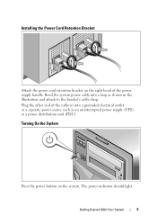
The power indicator should light. Installing the Power Cord Retention Bracket Attach the power cord retention bracket on the system. Getting Started With Your System 5 Bend the system power cable into a grounded electrical outlet or a separate power source such as shown in the illustration and attach to the bracket's cable clasp. Turning On the System Press the power button on the right bend of the cable(s) into a loop as an uninterrupted power supply (UPS) or a power distribution unit (PDU). Plug the other end of the power supply handle.
The power indicator should light. Installing the Power Cord Retention Bracket Attach the power cord retention bracket on the system. Getting Started With Your System 5 Bend the system power cable into a grounded electrical outlet or a separate power source such as shown in the illustration and attach to the bracket's cable clasp. Turning On the System Press the power button on the right bend of the cable(s) into a loop as an uninterrupted power supply (UPS) or a power distribution unit (PDU). Plug the other end of the power supply handle.

Getting Started Guide
Page 12
Connectors (continued) Front USB Internal USB Two 4-pin, USB 2.0-compliant Two 4-pin, USB 2.0-compliant Video Video type Video memory Matrox G200, integrated in Winbond WPCM450 8 MB Power AC power supply (per power supply) Wattage 525 W (Non-redundant power supply) 580 W (Redundant power supply) Voltage 100-240 VAC, 50/60 Hz, 8.2 A (Non-redundant power supply) 100-240 VAC, 50/60 Hz, 10 A (Redundant power supply) At 60 Hz 90 V, 4.46 A 100 V, 4.04 A 240 V, 1.65 A 254 V, 1.57 A At 50 Hz 90 V, 4.47 A 100 V, 4.05 A 240 V, 1.66 A 254 V, 1.58 A 10 Getting Started With Your System
Connectors (continued) Front USB Internal USB Two 4-pin, USB 2.0-compliant Two 4-pin, USB 2.0-compliant Video Video type Video memory Matrox G200, integrated in Winbond WPCM450 8 MB Power AC power supply (per power supply) Wattage 525 W (Non-redundant power supply) 580 W (Redundant power supply) Voltage 100-240 VAC, 50/60 Hz, 8.2 A (Non-redundant power supply) 100-240 VAC, 50/60 Hz, 10 A (Redundant power supply) At 60 Hz 90 V, 4.46 A 100 V, 4.04 A 240 V, 1.65 A 254 V, 1.57 A At 50 Hz 90 V, 4.47 A 100 V, 4.05 A 240 V, 1.66 A 254 V, 1.58 A 10 Getting Started With Your System
Getting Started Guide
Page 13
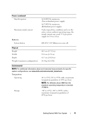
...Environmental NOTE: For additional information about environmental measurements for 10 ms or less. Power (continued) Heat dissipation Maximum inrush current Batteries System battery 1650 BTU/hr maximum (Non-redundant power supply) 1627 BTU/hr maximum (Redundant power supply) Under typical line conditions and over the entire system ambient operating range, the ... 11 Temperature Operating 10° to 35°C (50° to 149°F) with a maximum temperature gradation of 20°C per power supply for specific system configurations, see www.dell.com/environmental_datasheets.
...Environmental NOTE: For additional information about environmental measurements for 10 ms or less. Power (continued) Heat dissipation Maximum inrush current Batteries System battery 1650 BTU/hr maximum (Non-redundant power supply) 1627 BTU/hr maximum (Redundant power supply) Under typical line conditions and over the entire system ambient operating range, the ... 11 Temperature Operating 10° to 35°C (50° to 149°F) with a maximum temperature gradation of 20°C per power supply for specific system configurations, see www.dell.com/environmental_datasheets.
Hardware Owner's Manual
Page 6
... Guidelines. . . . . . 114 Installing an Expansion Card 115 Removing an Expansion Card 118 RAID Battery (Optional 119 Removing the RAID Battery 119 Installing a RAID Battery 120 Power Supplies 121 Removing a Redundant Power Supply 121 Installing a Redundant Power Supply 122 Removing a Power Supply Blank 123 6 Contents
... Guidelines. . . . . . 114 Installing an Expansion Card 115 Removing an Expansion Card 118 RAID Battery (Optional 119 Removing the RAID Battery 119 Installing a RAID Battery 120 Power Supplies 121 Removing a Redundant Power Supply 121 Installing a Redundant Power Supply 122 Removing a Power Supply Blank 123 6 Contents
Hardware Owner's Manual
Page 7
Installing a Power Supply Blank 123 Removing a Non-Redundant Power Supply 123 Installing a Non-Redundant Power Supply 125 Internal USB Memory Key 125 Integrated Dell Remote Access Controller 6 (iDRAC6) Express Card (Optional 127 Installing an iDRAC6 Express Card 127 Removing an iDRAC6 Express Card 128 Integrated Dell Remote Access Controller 6 (iDRAC6) Enterprise Card (Optional 129 Installing an iDRAC6 Enterprise Card...
Installing a Power Supply Blank 123 Removing a Non-Redundant Power Supply 123 Installing a Non-Redundant Power Supply 125 Internal USB Memory Key 125 Integrated Dell Remote Access Controller 6 (iDRAC6) Express Card (Optional 127 Installing an iDRAC6 Express Card 127 Removing an iDRAC6 Express Card 128 Integrated Dell Remote Access Controller 6 (iDRAC6) Enterprise Card (Optional 129 Installing an iDRAC6 Enterprise Card...
Hardware Owner's Manual
Page 9
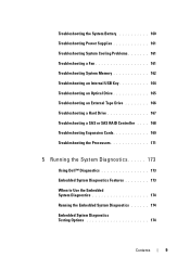
Troubleshooting the System Battery 160 Troubleshooting Power Supplies 161 Troubleshooting System Cooling Problems 161 Troubleshooting a Fan 161 Troubleshooting System Memory 162 Troubleshooting an Internal USB Key 164 Troubleshooting... a SAS or SAS RAID Controller . . . . 168 Troubleshooting Expansion Cards 169 Troubleshooting the Processors 171 5 Running the System Diagnostics 173 Using Dell™ Diagnostics 173 Embedded System Diagnostics Features 173 When to Use the Embedded System Diagnostics 174 Running the Embedded System Diagnostics 174 Embedded System Diagnostics...
Troubleshooting the System Battery 160 Troubleshooting Power Supplies 161 Troubleshooting System Cooling Problems 161 Troubleshooting a Fan 161 Troubleshooting System Memory 162 Troubleshooting an Internal USB Key 164 Troubleshooting... a SAS or SAS RAID Controller . . . . 168 Troubleshooting Expansion Cards 169 Troubleshooting the Processors 171 5 Running the System Diagnostics 173 Using Dell™ Diagnostics 173 Embedded System Diagnostics Features 173 When to Use the Embedded System Diagnostics 174 Running the Embedded System Diagnostics 174 Embedded System Diagnostics...
Hardware Owner's Manual
Page 13
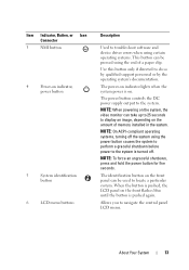
...control panel LCD menu. Use this button only if directed to display an image, depending on the amount of a paper clip. NOTE: When powering on the system, the video monitor can be used to locate a particular system. NOTE: On ACPI-compliant operating systems, turning off . ...LCD menu buttons Description Used to the system. NOTE: To force an ungraceful shutdown, press and hold the power button for five seconds. The power button controls the DC power supply output to troubleshoot software and device driver errors when using certain operating systems. This button can take up to...
...control panel LCD menu. Use this button only if directed to display an image, depending on the amount of a paper clip. NOTE: When powering on the system, the video monitor can be used to locate a particular system. NOTE: On ACPI-compliant operating systems, turning off . ...LCD menu buttons Description Used to the system. NOTE: To force an ungraceful shutdown, press and hold the power button for five seconds. The power button controls the DC power supply output to troubleshoot software and device driver errors when using certain operating systems. This button can take up to...
Hardware Owner's Manual
Page 22
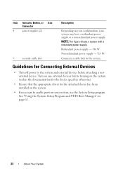
...Setup Program and UEFI Boot Manager" on your system may have a redundant power supply or a non-redundant power supply. NOTE: The figure shows a system with a redundant power supply. Redundant power supply - 580 W Non-redundant power supply - 525 W Connects a cable lock to enable ports on page 61.... the appropriate driver for Connecting External Devices • Turn off power to the system and external devices before attaching a new external device. Item Indicator, Button, or Icon Connector 8 power supplies (2) 9 security cable slot Description Depending on your configuration, your...
...Setup Program and UEFI Boot Manager" on your system may have a redundant power supply or a non-redundant power supply. NOTE: The figure shows a system with a redundant power supply. Redundant power supply - 580 W Non-redundant power supply - 525 W Connects a cable lock to enable ports on page 61.... the appropriate driver for Connecting External Devices • Turn off power to the system and external devices before attaching a new external device. Item Indicator, Button, or Icon Connector 8 power supplies (2) 9 security cable slot Description Depending on your configuration, your...
Hardware Owner's Manual
Page 23
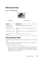
... Figure 1-5. NIC Indicator Codes 1 2 1 link indicator 2 activity indicator Indicator Indicator Code Link and activity indicators are off The NIC is not connected to the power supply and that show whether power is on system power status. Activity indicator is green Network data is not connected. • Green - When the system is present or whether...
... Figure 1-5. NIC Indicator Codes 1 2 1 link indicator 2 activity indicator Indicator Indicator Code Link and activity indicators are off The NIC is not connected to the power supply and that show whether power is on system power status. Activity indicator is green Network data is not connected. • Green - When the system is present or whether...
Hardware Owner's Manual
Page 24
... the same system). Figure 1-6. CAUTION: When correcting a power supply mismatch, replace only the power supply with the power supply. • Alternating green and amber - Redundant Power Supply Status Indicator 1 1 power supply status A non-redundant power supply has an LED indicator that shows whether power is mismatched with the other installed power supply. • Amber - Swapping the opposite power supply to an Energy Smart configuration or vice versa...
... the same system). Figure 1-6. CAUTION: When correcting a power supply mismatch, replace only the power supply with the power supply. • Alternating green and amber - Redundant Power Supply Status Indicator 1 1 power supply status A non-redundant power supply has an LED indicator that shows whether power is mismatched with the other installed power supply. • Amber - Swapping the opposite power supply to an Energy Smart configuration or vice versa...

Hardware Owner's Manual
Page 25
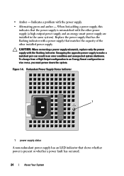
In standby mode, a green light indicates that the power supply is operational. About Your System 25 When the system is on, a green light also indicates that the power supply is providing DC power to the power supply and that a valid AC source is not connected. • Green - Non-Redundant Power Supply Status Indicator 1 2 1 power supply test switch 2 power supply status • Not lit - AC power is connected to the system. Figure 1-7.
In standby mode, a green light indicates that the power supply is operational. About Your System 25 When the system is on, a green light also indicates that the power supply is providing DC power to the power supply and that a valid AC source is not connected. • Green - Non-Redundant Power Supply Status Indicator 1 2 1 power supply test switch 2 power supply status • Not lit - AC power is connected to the system. Figure 1-7.

Hardware Owner's Manual
Page 32
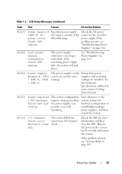
... for 10 seconds and error. The system BIOS has Remove AC power to the system for the specified power supply. E1610 Power Supply # Specified power supply See "Troubleshooting (### W) was removed or is attached to the system, but it has lost AC power. Check power supply. See "Troubleshooting Power Supplies" on missing. E161C Power Supply # (### W) lost its AC input. If the problem persists, see "Getting...
... for 10 seconds and error. The system BIOS has Remove AC power to the system for the specified power supply. E1610 Power Supply # Specified power supply See "Troubleshooting (### W) was removed or is attached to the system, but it has lost AC power. Check power supply. See "Troubleshooting Power Supplies" on missing. E161C Power Supply # (### W) lost its AC input. If the problem persists, see "Getting...
Hardware Owner's Manual
Page 33
... system's Getting Started Guide. See = ### W. The system configuration requires more information and then clear the SEL. About Your System 33 Check the AC power source for more power than the power supplies can provide, even with matching = ### W, PSU2 wattage. reported an I /O channel The system BIOS has check error. LCD Status Messages (continued) Code Text...
... system's Getting Started Guide. See = ### W. The system configuration requires more information and then clear the SEL. About Your System 33 Check the AC power source for more power than the power supplies can provide, even with matching = ### W, PSU2 wattage. reported an I /O channel The system BIOS has check error. LCD Status Messages (continued) Code Text...

Hardware Owner's Manual
Page 41
... restart the system. In contrast, you know that is a failing power supply. when the temperature returns to a normal state. requires more power than system, reduce the Check PSU and what the power supply can hardware configuration or system provide, but it can boot if install ...other faults, you might be able to the degraded. provide. install higher-wattage power supplies, and then restart the system. requires more power than system, reduce the Check PSU and what the power supply can often specify a very precise fault condition that a microprocessor is removed from ...
... restart the system. In contrast, you know that is a failing power supply. when the temperature returns to a normal state. requires more power than system, reduce the Check PSU and what the power supply can hardware configuration or system provide, but it can boot if install ...other faults, you might be able to the degraded. provide. install higher-wattage power supplies, and then restart the system. requires more power than system, reduce the Check PSU and what the power supply can often specify a very precise fault condition that a microprocessor is removed from ...

Hardware Owner's Manual
Page 44
... additional information for failure. Check PSU and system configuration. If Energy Smart power supplies are not supported with High Output power supplies to use the components. Redundant memory disabled! See "Power Supplies" on page 61. 44 About Your System Memory configuration does not support ... boot accepts the risk that supports configuration has changed node interleaving. See "Using the may be supported by the power supplies. If any system components were just upgraded, return the system to run, but "Troubleshooting System the current configuration Memory...
... additional information for failure. Check PSU and system configuration. If Energy Smart power supplies are not supported with High Output power supplies to use the components. Redundant memory disabled! See "Power Supplies" on page 61. 44 About Your System Memory configuration does not support ... boot accepts the risk that supports configuration has changed node interleaving. See "Using the may be supported by the power supplies. If any system components were just upgraded, return the system to run, but "Troubleshooting System the current configuration Memory...


