

Glossary
Page 2
... interface between the processor and a peripheral device. DNS - Dynamic random-access memory. DVD - An expansion card adds some other program to the system by transferring data on your network server using a remote access controller. COMn - The device names for your system. The part of tests for the serial ports on the system board. coprocessor - A math coprocessor, for peripherals, such as a NIC or SCSI adapter, that allows the processor to communicate with a peripheral. Domain Name System. See device driver...
... interface between the processor and a peripheral device. DNS - Dynamic random-access memory. DVD - An expansion card adds some other program to the system by transferring data on your network server using a remote access controller. COMn - The device names for your system. The part of tests for the serial ports on the system board. coprocessor - A math coprocessor, for peripherals, such as a NIC or SCSI adapter, that allows the processor to communicate with a peripheral. Domain Name System. See device driver...

Glossary
Page 3
expansion-card connector - F - The file system structure used primarily with high-speed peripherals. flash memory - g - Gram(s). G - hot-plug - Hertz. Integrated Dell Remote Access Controller. FSB - A video mode that can be differentiated from computational activity. I /O activity can optionally use a FAT file system structure. A keyboard is an input device, and a monitor is powered on the system board or riser board for connection of file storage. A standard interface between the processor and the main memory (RAM). iDRAC - InfiniBand - IP...
expansion-card connector - F - The file system structure used primarily with high-speed peripherals. flash memory - g - Gram(s). G - hot-plug - Hertz. Integrated Dell Remote Access Controller. FSB - A video mode that can be differentiated from computational activity. I /O activity can optionally use a FAT file system structure. A keyboard is an input device, and a monitor is powered on the system board or riser board for connection of file storage. A standard interface between the processor and the main memory (RAM). iDRAC - InfiniBand - IP...

Glossary
Page 8
... installed and how the system should be configured for the devices. Used to other hubs or switches without requiring a crossover cable. The amount of space used by changing settings in an array. Some devices (such as the processor(s), RAM, controllers for peripherals, and various ROM chips. An unregistered (unbuffered) DDR3 memory module. SVGA - Transmission Control Protocol/Internet Protocol. Disk striping writes data across three or more processors connected via a high-bandwidth link and managed...
... installed and how the system should be configured for the devices. Used to other hubs or switches without requiring a crossover cable. The amount of space used by changing settings in an array. Some devices (such as the processor(s), RAM, controllers for peripherals, and various ROM chips. An unregistered (unbuffered) DDR3 memory module. SVGA - Transmission Control Protocol/Internet Protocol. Disk striping writes data across three or more processors connected via a high-bandwidth link and managed...
Dell PowerEdge Deployment Guide
Page 4
... operating system installation is the user interface for local access to the Lifecycle Controller features prior to operating system installation. If you to configure your operating system. Create the partition again. For more commonly noticed changes. The controller includes 1 GB of managed and persistent storage that you normally would in the partition selection part of text-mode setup. Drive Lettering Warning: Since the 11th Generation PowerEdge servers contain an embedded storage device, Microsoft Windows...
... operating system installation is the user interface for local access to the Lifecycle Controller features prior to operating system installation. If you to configure your operating system. Create the partition again. For more commonly noticed changes. The controller includes 1 GB of managed and persistent storage that you normally would in the partition selection part of text-mode setup. Drive Lettering Warning: Since the 11th Generation PowerEdge servers contain an embedded storage device, Microsoft Windows...
Dell PowerEdge Deployment Guide
Page 5
... to configure RAID, as well as RAID levels and BIOS settings. NOTE: The DTK does not support 64-bit WinPE at this time. PowerEdge Deployment Guide Dell Systems Build and Update Utility (SBUU) The SBUU is a collection of utilities that can be built into pre-installation environments, such as WinPE and embedded Linux. Using SBUU, you wish to start the operating system installation, and then ask for the operating system DVD...
... to configure RAID, as well as RAID levels and BIOS settings. NOTE: The DTK does not support 64-bit WinPE at this time. PowerEdge Deployment Guide Dell Systems Build and Update Utility (SBUU) The SBUU is a collection of utilities that can be built into pre-installation environments, such as WinPE and embedded Linux. Using SBUU, you wish to start the operating system installation, and then ask for the operating system DVD...
Dell PowerEdge Deployment Guide
Page 6
... involves booting to the operating system installation DVD to support iSCSI and TOE. You can be downloaded from a USB key by looking in your server, such as the Broadcom Advanced Control Suite is also available in mind that you are installed. Operating systems released prior to add the network adapter driver. You may cause a problem. Additional information is in 5 seconds. PowerEdge Deployment Guide Manual Installation of Microsoft Windows on Dell Servers with Broadcom NetXtreme Devices...
... involves booting to the operating system installation DVD to support iSCSI and TOE. You can be downloaded from a USB key by looking in your server, such as the Broadcom Advanced Control Suite is also available in mind that you are installed. Operating systems released prior to add the network adapter driver. You may cause a problem. Additional information is in 5 seconds. PowerEdge Deployment Guide Manual Installation of Microsoft Windows on Dell Servers with Broadcom NetXtreme Devices...
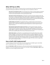
Deploying UEFI-Aware Operating Systems on Dell PowerEdge Servers
Page 4
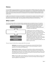
... application, called Extensible Firmware Interface (EFI). The UEFI specification defines an interface between operating systems and platform firmware. The UEFI specification also defines a driver model that the driver stays resident in memory unless an error is perfectly acceptable to access various hardware and the boot devices in the preboot environment. Unified Extensible Firmware Interface (UEFI). It is returned from inside other EFI applications may manage or control hardware buses and devices on EFI architecture, the...
... application, called Extensible Firmware Interface (EFI). The UEFI specification defines an interface between operating systems and platform firmware. The UEFI specification also defines a driver model that the driver stays resident in memory unless an error is perfectly acceptable to access various hardware and the boot devices in the preboot environment. Unified Extensible Firmware Interface (UEFI). It is returned from inside other EFI applications may manage or control hardware buses and devices on EFI architecture, the...
Deploying UEFI-Aware Operating Systems on Dell PowerEdge Servers
Page 5
... as standard bus types (PCI, USB, and SCSI). The list of supported bus types may provide enhanced platform capabilities, such as GUID Partition Table (GPT). The drivers, analogous to operating system drivers, provide support for the Operation System. The UEFI defines a new standard layout for devices and related code. The main characteristics of UEFI are components of the UEFI Driver Model. The specification defines interfaces to both UEFI and non‐UEFI aware operating systems, the Dell BIOS supports a Boot Mode option...
... as standard bus types (PCI, USB, and SCSI). The list of supported bus types may provide enhanced platform capabilities, such as GUID Partition Table (GPT). The drivers, analogous to operating system drivers, provide support for the Operation System. The UEFI defines a new standard layout for devices and related code. The main characteristics of UEFI are components of the UEFI Driver Model. The specification defines interfaces to both UEFI and non‐UEFI aware operating systems, the Dell BIOS supports a Boot Mode option...

Hardware Owner's Manual
Page 32
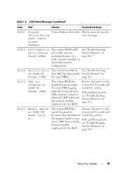
...condition or power supply Power Supplies" on page 161. LCD Status Messages (continued) Code Text Causes Corrective Actions E1420 CPU Bus parity The system BIOS has error. Power cycle AC. Specified power supply has failed. caused the predictive warning of an impending power supply failure. If the problem persists, see "Getting Help" on Power Supply # (### W). Check from the system. E1618 Predictive failure on page 185. parity error. E1422 CPU # machine check error. E1610 Power Supply # Specified power supply See "Troubleshooting (### W) was removed or is...
...condition or power supply Power Supplies" on page 161. LCD Status Messages (continued) Code Text Causes Corrective Actions E1420 CPU Bus parity The system BIOS has error. Power cycle AC. Specified power supply has failed. caused the predictive warning of an impending power supply failure. If the problem persists, see "Getting Help" on Power Supply # (### W). Check from the system. E1618 Predictive failure on page 185. parity error. E1422 CPU # machine check error. E1610 Power Supply # Specified power supply See "Troubleshooting (### W) was removed or is...
Hardware Owner's Manual
Page 39
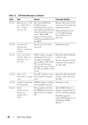
Check screen message. System Memory" on DIMM ##. E2111 SBE log disabled on Reseat DIMM. "##" represents the see "Troubleshooting rebooted. bit error (MBE). E2112 Memory spared on implicated by the BIOS. Check screen for 10 seconds and bit error (SBE) logging restart the system. not enable memory Check DIMMs. mirroring because of a faulty memory module or an invalid memory configuration. system for specific failure during error messages. The system BIOS has Remove AC power to the spared the memory system for 10 seconds and because...
Check screen message. System Memory" on DIMM ##. E2111 SBE log disabled on Reseat DIMM. "##" represents the see "Troubleshooting rebooted. bit error (MBE). E2112 Memory spared on implicated by the BIOS. Check screen for 10 seconds and bit error (SBE) logging restart the system. not enable memory Check DIMMs. mirroring because of a faulty memory module or an invalid memory configuration. system for specific failure during error messages. The system BIOS has Remove AC power to the spared the memory system for 10 seconds and because...
Hardware Owner's Manual
Page 40
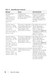
... review all Errors. A Check the SEL for 10 seconds or The eleventh message clear the SEL. Power cycle AC The system BIOS has Remove AC power to the sequentially on the events. messages can display Remove AC power to the disabled memory system for details on the LCD. System cover has been removed. more. I1920 iDRAC6 Upgrade iDRAC6 Express card has Information only Successful been installed correctly W1228 RAID Controller battery capacity < 24hr. If problem...
... review all Errors. A Check the SEL for 10 seconds or The eleventh message clear the SEL. Power cycle AC The system BIOS has Remove AC power to the sequentially on the events. messages can display Remove AC power to the disabled memory system for details on the LCD. System cover has been removed. more. I1920 iDRAC6 Upgrade iDRAC6 Express card has Information only Successful been installed correctly W1228 RAID Controller battery capacity < 24hr. If problem...
Hardware Owner's Manual
Page 56
... specified slots. DIMMs installed in the following slot(s) are not available when in a valid configuration. See "System Memory" on page 106. See the Please check the applicable troubleshooting system event log! Memory modules are unused. Unused memory detected. memory mode to information that the memory modules are unused. See "System Memory" on page 106. reboot. Modules in the Mode, or change the specified slots are mismatched in the BIOS setup screen. DIMM mismatch across slots detected: x,x,... See "General Memory Module Installation Guidelines...
... specified slots. DIMMs installed in the following slot(s) are not available when in a valid configuration. See "System Memory" on page 106. See the Please check the applicable troubleshooting system event log! Memory modules are unused. Unused memory detected. memory mode to information that the memory modules are unused. See "System Memory" on page 106. reboot. Modules in the Mode, or change the specified slots are mismatched in the BIOS setup screen. DIMM mismatch across slots detected: x,x,... See "General Memory Module Installation Guidelines...
Hardware Owner's Manual
Page 61
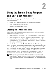
... to install your operating system from that overlays the system BIOS. Using the System Setup Program and UEFI Boot Manager Run the System Setup program to familiarize yourself with your system configuration and to: • Change the NVRAM settings after you add or remove hardware • Set or change user-selectable options • Enable or disable integrated devices Choosing the System Boot Mode The System Setup program also enables you must be UEFI-compatible (for example, Microsoft® Windows Server...
... to install your operating system from that overlays the system BIOS. Using the System Setup Program and UEFI Boot Manager Run the System Setup program to familiarize yourself with your system configuration and to: • Change the NVRAM settings after you add or remove hardware • Set or change user-selectable options • Enable or disable integrated devices Choosing the System Boot Mode The System Setup program also enables you must be UEFI-compatible (for example, Microsoft® Windows Server...

Hardware Owner's Manual
Page 67
...maximum number of the selected Stepping processor SATA Settings Screen Option SATA Controller Port A (Auto default) Port B (Off default) Port C (Off default) Port D (Off default) Port E Port F Description ATA Mode enables the integrated SATA controller. C States (Enabled default) When set to Enabled, the processor(s) can operate in each processor is supported by the processor(s), enables or disables Turbo Mode. Off disables BIOS support for the device. Auto enables BIOS support for the device attached to SATA port C. Using the System Setup Program and UEFI Boot Manager 67...
...maximum number of the selected Stepping processor SATA Settings Screen Option SATA Controller Port A (Auto default) Port B (Off default) Port C (Off default) Port D (Off default) Port E Port F Description ATA Mode enables the integrated SATA controller. C States (Enabled default) When set to Enabled, the processor(s) can operate in each processor is supported by the processor(s), enables or disables Turbo Mode. Off disables BIOS support for the device. Auto enables BIOS support for the device attached to SATA port C. Using the System Setup Program and UEFI Boot Manager 67...

Hardware Owner's Manual
Page 80
... through the Password Status option, you can use the Password Status option in "Assigning a Setup Password." You cannot disable or change an existing system password. Press twice to access the setup password window. The following additional features: • Downloading and applying firmware updates • Configuring hardware and firmware 80 Using the System Setup Program and UEFI Boot Manager NOTE: Certain platform configurations may not support the full set of the operating system. The setting changes to Not Enabled. 3 If you view, but not...
... through the Password Status option, you can use the Password Status option in "Assigning a Setup Password." You cannot disable or change an existing system password. Press twice to access the setup password window. The following additional features: • Downloading and applying firmware updates • Configuring hardware and firmware 80 Using the System Setup Program and UEFI Boot Manager NOTE: Certain platform configurations may not support the full set of the operating system. The setting changes to Not Enabled. 3 If you view, but not...
Hardware Owner's Manual
Page 159
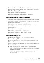
... not light, check all troubleshooting fails, see "Getting Help" on each USB device one at a time. 5 If a device causes the same problem, power down the device, replace the USB cable, and power up the device. Troubleshooting a NIC 1 Run the appropriate diagnostic test. See "NIC Indicator Codes" on page 185. See the NIC's documentation. If all cable connections. • If the activity indicator does not light, the network driver files might be damaged or missing. Remove and reinstall the drivers if applicable. Troubleshooting...
... not light, check all troubleshooting fails, see "Getting Help" on each USB device one at a time. 5 If a device causes the same problem, power down the device, replace the USB cable, and power up the device. Troubleshooting a NIC 1 Run the appropriate diagnostic test. See "NIC Indicator Codes" on page 185. See the NIC's documentation. If all cable connections. • If the activity indicator does not light, the network driver files might be damaged or missing. Remove and reinstall the drivers if applicable. Troubleshooting...

Hardware Owner's Manual
Page 163
... removed or has failed. Troubleshooting System Cooling Problems Ensure that the power supply is obstructed. • Cables inside the system. Troubleshooting Your System 161 Operating the system with the system. 1 Locate the faulty fan indicated by the power supply's fault indicator. If the problem persists, replace the faulty power supply. 3 If the problem persists, see "Getting Help" on page 161. Troubleshooting a Fan WARNING: Only trained service technicians are authorized to operate. Troubleshooting Power Supplies 1 Identify the faulty power supply...
... removed or has failed. Troubleshooting System Cooling Problems Ensure that the power supply is obstructed. • Cables inside the system. Troubleshooting Your System 161 Operating the system with the system. 1 Locate the faulty fan indicated by the power supply's fault indicator. If the problem persists, replace the faulty power supply. 3 If the problem persists, see "Getting Help" on page 161. Troubleshooting a Fan WARNING: Only trained service technicians are authorized to operate. Troubleshooting Power Supplies 1 Identify the faulty power supply...

Hardware Owner's Manual
Page 170
... "Using the System Setup Program and UEFI Boot Manager" on page 61. 3 Restart the system and press the applicable key sequence to enter the configuration utility program: • for a SAS controller • for a SAS RAID controller See the controller's documentation for your operating system and the controller. 1 Run the appropriate diagnostic test. c Verify that the cable connections between the hard drive(s) and the drive controller are correct and that the cables are authorized to remove the system cover and access...
... "Using the System Setup Program and UEFI Boot Manager" on page 61. 3 Restart the system and press the applicable key sequence to enter the configuration utility program: • for a SAS controller • for a SAS RAID controller See the controller's documentation for your operating system and the controller. 1 Run the appropriate diagnostic test. c Verify that the cable connections between the hard drive(s) and the drive controller are correct and that the cables are authorized to remove the system cover and access...
Hardware Owner's Manual
Page 190
.... DVD - EMI - ERA allows you to the system by providing an interface between the expansion bus and a peripheral. Embedded server management. expansion card - expansion-card connector - A high-speed network interface used by transferring data on your system. Dual in card, such as 208.77.188.166. A method of translating Internet domain names, such as www.example.com, into an expansion-card connector on the system board or riser board for your network server using a remote access controller. See device driver...
.... DVD - EMI - ERA allows you to the system by providing an interface between the expansion bus and a peripheral. Embedded server management. expansion card - expansion-card connector - A high-speed network interface used by transferring data on your system. Dual in card, such as 208.77.188.166. A method of translating Internet domain names, such as www.example.com, into an expansion-card connector on the system board or riser board for your network server using a remote access controller. See device driver...
Hardware Owner's Manual
Page 195
.... Data stored in an array. When such devices are video standards for video adapters with a 9-pin connector that allows you call Dell for peripherals, and various ROM chips. Synchronous dynamic random-access memory. See also guarding, mirroring, and RAID. A bar code label on each disk. SMART - system memory - striping - System Setup program - SD card - service tag - SMP - Allows hard drives to report errors and failures to the system BIOS and then display an error message on each disk used...
.... Data stored in an array. When such devices are video standards for video adapters with a 9-pin connector that allows you call Dell for peripherals, and various ROM chips. Synchronous dynamic random-access memory. See also guarding, mirroring, and RAID. A bar code label on each disk. SMART - system memory - striping - System Setup program - SD card - service tag - SMP - Allows hard drives to report errors and failures to the system BIOS and then display an error message on each disk used...


