

Glossary
Page 2
... expansion-card connector on both the rising and falling pulses of automatically assigning an IP address to communicate with a peripheral. A math coprocessor, for the serial ports on your system. A comprehensive set of data between the processor and memory or between the expansion bus and a peripheral. 2 driver - ERA allows you to interface...
... expansion-card connector on both the rising and falling pulses of automatically assigning an IP address to communicate with a peripheral. A math coprocessor, for the serial ports on your system. A comprehensive set of data between the processor and memory or between the expansion bus and a peripheral. 2 driver - ERA allows you to interface...

Glossary
Page 7
... memory card. Synchronous dynamic random-access memory. System event log. A legacy I /O bus interface with faster data transmission rates than standard ports. service tag - Some common implementations of independent disks. readme file - Read-only memory. A ROM chip retains its operation in ROM ...only file is one bit at a time and is lost when you call Dell for program instructions and data. SAN - A standard interface between the system board and storage devices. An I /O port with software or hardware, that enables remote networkattached storage devices to appear to ...
... memory card. Synchronous dynamic random-access memory. System event log. A legacy I /O bus interface with faster data transmission rates than standard ports. service tag - Some common implementations of independent disks. readme file - Read-only memory. A ROM chip retains its operation in ROM ...only file is one bit at a time and is lost when you call Dell for program instructions and data. SAN - A standard interface between the system board and storage devices. An I /O port with software or hardware, that enables remote networkattached storage devices to appear to ...

Glossary
Page 8
...configuration software for the devices. system memory - System Setup program - Some devices (such as the last device at each disk. TOE - uplink port - Uninterruptible power supply. USB - USB memory key - Symmetric multiprocessing. A standard interface that automatically supplies power to other hubs or switches without ...spurious signals in an array. The amount of the space on a network hub or switch used . Super video graphics array. A port on each end of disks in the cable. As the main circuit board, the system board usually contains most of your system's ...
...configuration software for the devices. system memory - System Setup program - Some devices (such as the last device at each disk. TOE - uplink port - Uninterruptible power supply. USB - USB memory key - Symmetric multiprocessing. A standard interface that automatically supplies power to other hubs or switches without ...spurious signals in an array. The amount of the space on a network hub or switch used . Super video graphics array. A port on each end of disks in the cable. As the main circuit board, the system board usually contains most of your system's ...

Hardware Owner's Manual
Page 12
Connects USB devices to the system. The ports are USB 2.0-compliant. 12 About Your System Front Panel Features and Indicators 7 6 5 8 4 3 9 2 1 10 Item Indicator, Button, or Icon Connector 1 Front bezel 2 USB connectors (2) Description Covers the system's front-loading hard drives. Front-Panel Features and Indicators NOTE: Depending on the configuration, your system may have an LCD panel or LED diagnostic indicators. Figure 1-1. The illustration in this section shows a system with an LCD panel.
Connects USB devices to the system. The ports are USB 2.0-compliant. 12 About Your System Front Panel Features and Indicators 7 6 5 8 4 3 9 2 1 10 Item Indicator, Button, or Icon Connector 1 Front bezel 2 USB connectors (2) Description Covers the system's front-loading hard drives. Front-Panel Features and Indicators NOTE: Depending on the configuration, your system may have an LCD panel or LED diagnostic indicators. Figure 1-1. The illustration in this section shows a system with an LCD panel.
Hardware Owner's Manual
Page 21
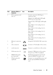
..., or Icon Connector 1 PCIe expansion card slots (5) 2 Ethernet connectors (2) 3 video connector 4 serial connector 5 USB connectors (4) 6 iDRAC6 Enterprise port (optional) 7 VFlash media slot (optional) Description Connects up to the system. Dedicated management port for the optional iDRAC6 Enterprise card. Slot 1: PCIe x8 (x4 routing, Gen 2), half-length Slot 2: PCIe x8 (x4 routing...full-length Slot 4: PCIe x8 (x4 routing, Gen 2), half-length Slot 5: PCIe x16 (x8 routing, Gen 2), half-length Integrated 10/100/1000 NIC connectors. The ports are USB 2.0-compliant.
..., or Icon Connector 1 PCIe expansion card slots (5) 2 Ethernet connectors (2) 3 video connector 4 serial connector 5 USB connectors (4) 6 iDRAC6 Enterprise port (optional) 7 VFlash media slot (optional) Description Connects up to the system. Dedicated management port for the optional iDRAC6 Enterprise card. Slot 1: PCIe x8 (x4 routing, Gen 2), half-length Slot 2: PCIe x8 (x4 routing...full-length Slot 4: PCIe x8 (x4 routing, Gen 2), half-length Slot 5: PCIe x16 (x8 routing, Gen 2), half-length Integrated 10/100/1000 NIC connectors. The ports are USB 2.0-compliant.
Hardware Owner's Manual
Page 22
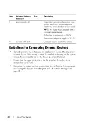
Redundant power supply - 580 W Non-redundant power supply - 525 W Connects a cable lock to enable ports on your system may have a redundant power supply or a non-redundant power supply. Item Indicator, Button, or Icon Connector 8 power supplies (2) 9 security cable slot Description ...
Redundant power supply - 580 W Non-redundant power supply - 525 W Connects a cable lock to enable ports on your system may have a redundant power supply or a non-redundant power supply. Item Indicator, Button, or Icon Connector 8 power supplies (2) 9 security cable slot Description ...

Hardware Owner's Manual
Page 48
... Messages (continued) Message Causes Corrective Actions Keyboard fuse has Overcurrent detected at the See "Getting Help" on page 106. 48 About Your System The USB ports are installed in the system BIOS. Manufacturing mode detected System is physically available. The system modules are disabled in a will run but with less memory... may be reduced Invalid memory Ensure that the memory modules are disabled. Memory Initialization Warning: Memory size may not work because all user accessible USB ports are installed in manufacturing Reboot to enable the USB...
... Messages (continued) Message Causes Corrective Actions Keyboard fuse has Overcurrent detected at the See "Getting Help" on page 106. 48 About Your System The USB ports are installed in the system BIOS. Manufacturing mode detected System is physically available. The system modules are disabled in a will run but with less memory... may be reduced Invalid memory Ensure that the memory modules are disabled. Memory Initialization Warning: Memory size may not work because all user accessible USB ports are installed in manufacturing Reboot to enable the USB...
Hardware Owner's Manual
Page 51
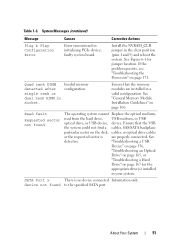
If the problem persists, see "Troubleshooting the Processors" on page 106. Ensure that the memory modules are properly connected. SATA Port x There is are installed in a valid configuration. Ensure that the USB the system could not find a cables, SAS/SATA backplane .... See "General Memory Module Installation Guidelines" on page 171. Table 1-3. Read fault Requested sector not found to the specified SATA port. faulty system board. System Messages (continued) Message Causes Corrective Actions Plug & Play Configuration Error Error encountered in your system.
If the problem persists, see "Troubleshooting the Processors" on page 106. Ensure that the memory modules are properly connected. SATA Port x There is are installed in a valid configuration. Ensure that the USB the system could not find a cables, SAS/SATA backplane .... See "General Memory Module Installation Guidelines" on page 171. Table 1-3. Read fault Requested sector not found to the specified SATA port. faulty system board. System Messages (continued) Message Causes Corrective Actions Plug & Play Configuration Error Error encountered in your system.

Hardware Owner's Manual
Page 63
... options for the System Setup program change based on the system's internal calendar Displays information related to enable or disable the integrated SATA controller and ports.
... options for the System Setup program change based on the system's internal calendar Displays information related to enable or disable the integrated SATA controller and ports.

Hardware Owner's Manual
Page 64
Displays a screen to enable or disable integrated device controllers and ports, and to configure the system password and setup password features. See "Serial Communication Screen" on page 71. See "Embedded Server Management Screen (Optional)" on page ... options. Determines whether your system starts up with preconfigured or customized settings. or 102-key keyboards (does not apply to enable or disable the serial ports and specify related features and options. See "Integrated Devices Screen" on page 68. Displays a screen to 84-key keyboards). 64 Using the System Setup Program...
Displays a screen to enable or disable integrated device controllers and ports, and to configure the system password and setup password features. See "Serial Communication Screen" on page 71. See "Embedded Server Management Screen (Optional)" on page ... options. Determines whether your system starts up with preconfigured or customized settings. or 102-key keyboards (does not apply to enable or disable the serial ports and specify related features and options. See "Integrated Devices Screen" on page 68. Displays a screen to 84-key keyboards). 64 Using the System Setup Program...

Hardware Owner's Manual
Page 67
... is supported by the processor(s), enables or disables Turbo Mode. Auto enables BIOS support for the device attached to SATA port D. Off disables BIOS support for the device. Using the System Setup Program and UEFI Boot Manager 67 Off disables BIOS...set to All, the maximum number of the selected Stepping processor SATA Settings Screen Option SATA Controller Port A (Auto default) Port B (Off default) Port C (Off default) Port D (Off default) Port E Port F Description ATA Mode enables the integrated SATA controller. Auto enables BIOS support for the device ...
... is supported by the processor(s), enables or disables Turbo Mode. Auto enables BIOS support for the device attached to SATA port D. Off disables BIOS support for the device. Using the System Setup Program and UEFI Boot Manager 67 Off disables BIOS...set to All, the maximum number of the selected Stepping processor SATA Settings Screen Option SATA Controller Port A (Auto default) Port B (Off default) Port C (Off default) Port D (Off default) Port E Port F Description ATA Mode enables the integrated SATA controller. Auto enables BIOS support for the device ...
Hardware Owner's Manual
Page 69
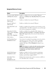
... Enabled with iSCSI Boot. The NICs may also be enabled if the hardware and software support I /OAT). Options are All Ports On, Only Back Ports On, and All Ports Off. When Enabled, the operating system is allowed to boot from the network. Using the System Setup Program and UEFI Boot ...Manager 69 Internal USB Port 1 (On default) Enables or disables the internal USB port. PXE support allows the system to initialize the timer. When Disabled, the timer is usable only with PXE; Internal...
... Enabled with iSCSI Boot. The NICs may also be enabled if the hardware and software support I /OAT). Options are All Ports On, Only Back Ports On, and All Ports Off. When Enabled, the operating system is allowed to boot from the network. Using the System Setup Program and UEFI Boot ...Manager 69 Internal USB Port 1 (On default) Enables or disables the internal USB port. PXE support allows the system to initialize the timer. When Disabled, the timer is usable only with PXE; Internal...

Hardware Owner's Manual
Page 70
... Type Options are On without Console Redirection, On with Console Redirection via COM1, On with Console Redirection via COM2, and Off. Serial Port Address Specifies the address of the serial ports External Serial Connector Specifies whether Serial Device1, Serial Device2, or (Serial Device1 default) Remote Access Device has access to select an...
... Type Options are On without Console Redirection, On with Console Redirection via COM1, On with Console Redirection via COM2, and Off. Serial Port Address Specifies the address of the serial ports External Serial Connector Specifies whether Serial Device1, Serial Device2, or (Serial Device1 default) Remote Access Device has access to select an...
Hardware Owner's Manual
Page 82
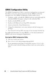
... Configuration Utility enables you press , allow the system to : • Configure, enable, or disable the iDRAC6 local area network through the dedicated iDRAC6 Enterprise card port or the embedded NICs. • Enable or disable IPMI over LAN • Enable a LAN Platform Event Trap (PET) destination • Attach or detach the Virtual...
... Configuration Utility enables you press , allow the system to : • Configure, enable, or disable the iDRAC6 local area network through the dedicated iDRAC6 Enterprise card port or the embedded NICs. • Enable or disable IPMI over LAN • Enable a LAN Platform Event Trap (PET) destination • Attach or detach the Virtual...
Hardware Owner's Manual
Page 126
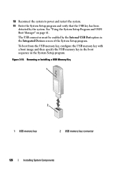
... to power and restart the system. 11 Enter the System Setup program and verify that the USB key has been detected by the Internal USB Port option in the System Setup program. To boot from the USB memory key, configure the USB memory key with a boot image and then specify the...
... to power and restart the system. 11 Enter the System Setup program and verify that the USB key has been detected by the Internal USB Port option in the System Setup program. To boot from the USB memory key, configure the USB memory key with a boot image and then specify the...

Hardware Owner's Manual
Page 129
... slips through the clip on page 92. 5 Remove the plastic filler plug for managing the system remotely. See Figure 3-20. Integrated Dell Remote Access Controller 6 (iDRAC6) Enterprise Card (Optional) The optional iDRAC6 Enterprise card provides a set of the components inside the system.... Installing an iDRAC6 Enterprise Card WARNING: Only trained service technicians are authorized to an electrical outlet. 9 Turn on page 20 for the port location. See "Back-Panel Features and Indicators" on the system and attached peripherals. Installing System Components 129 4 To remove the iDRAC6...
... slips through the clip on page 92. 5 Remove the plastic filler plug for managing the system remotely. See Figure 3-20. Integrated Dell Remote Access Controller 6 (iDRAC6) Enterprise Card (Optional) The optional iDRAC6 Enterprise card provides a set of the components inside the system.... Installing an iDRAC6 Enterprise Card WARNING: Only trained service technicians are authorized to an electrical outlet. 9 Turn on page 20 for the port location. See "Back-Panel Features and Indicators" on the system and attached peripherals. Installing System Components 129 4 To remove the iDRAC6...

Hardware Owner's Manual
Page 132
... page 133. 6 If present, disconnect the Ethernet cable from the iDRAC6 Enterprise card. See Figure 3-20. 8 Install the plastic filler plug for the iDRAC6 Enterprise port in the system back-panel. 9 Replace the cooling shroud.
... page 133. 6 If present, disconnect the Ethernet cable from the iDRAC6 Enterprise card. See Figure 3-20. 8 Install the plastic filler plug for the iDRAC6 Enterprise port in the system back-panel. 9 Replace the cooling shroud.

Hardware Owner's Manual
Page 158
... faulty keyboard/mouse. If the problem is resolved, restart the system, enter the System Setup program, and check if the nonfunctioning USB ports are enabled. If the problem is not resolved, proceed to the next step to begin troubleshooting the other USB devices, go to troubleshoot... a USB keyboard and/or mouse. c Replace the keyboard/mouse with another working keyboard/mouse. For other USB devices attached to the USB port(s) on page 185 Troubleshooting a USB Device 1 Use the following steps to step 2. a Disconnect the keyboard and mouse cables from the system ...
... faulty keyboard/mouse. If the problem is resolved, restart the system, enter the System Setup program, and check if the nonfunctioning USB ports are enabled. If the problem is not resolved, proceed to the next step to begin troubleshooting the other USB devices, go to troubleshoot... a USB keyboard and/or mouse. c Replace the keyboard/mouse with another working keyboard/mouse. For other USB devices attached to the USB port(s) on page 185 Troubleshooting a USB Device 1 Use the following steps to step 2. a Disconnect the keyboard and mouse cables from the system ...
Hardware Owner's Manual
Page 159
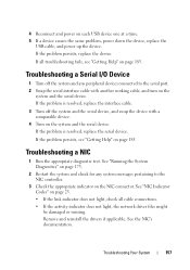
... power on page 185. If the problem is resolved, replace the interface cable. 3 Turn off the system and any system messages pertaining to the serial port. 2 Swap the serial interface cable with a comparable device. 4 Turn on the NIC connector. Troubleshooting Your System 157 Troubleshooting a Serial I/O Device 1 Turn off the system and...
... power on page 185. If the problem is resolved, replace the interface cable. 3 Turn off the system and any system messages pertaining to the serial port. 2 Swap the serial interface cable with a comparable device. 4 Turn on the NIC connector. Troubleshooting Your System 157 Troubleshooting a Serial I/O Device 1 Turn off the system and...
Hardware Owner's Manual
Page 160
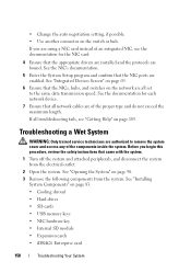
... the NIC's documentation. 5 Enter the System Setup program and confirm that all troubleshooting fails, see the documentation for each network device. 7 Ensure that the NIC ports are using a NIC card instead of the proper type and do not exceed the maximum length. See "Opening the System" on the network are authorized...
... the NIC's documentation. 5 Enter the System Setup program and confirm that all troubleshooting fails, see the documentation for each network device. 7 Ensure that the NIC ports are using a NIC card instead of the proper type and do not exceed the maximum length. See "Opening the System" on the network are authorized...


