

Glossary
Page 1
Advanced Configuration and Power Interface. A module that includes power supplies and fans. Celsius. CA - Certificate authority. cm - ACPI - Baseboard management controller. A CD, diskette, or USB memory key that is located. An ...address bus and a data bus for communications between the components of CIM data with controllers for quick data retrieval. blade - bootable media - Dell™ Glossary NOTE: For additional information on storage terminology, visit the Storage Networking Industry Association's website at www.snia.org and click on a...
Advanced Configuration and Power Interface. A module that includes power supplies and fans. Celsius. CA - Certificate authority. cm - ACPI - Baseboard management controller. A CD, diskette, or USB memory key that is located. An ...address bus and a data bus for communications between the components of CIM data with controllers for quick data retrieval. blade - bootable media - Dell™ Glossary NOTE: For additional information on storage terminology, visit the Storage Networking Industry Association's website at www.snia.org and click on a...

Glossary
Page 3
... system's bus and the peripheral device, typically a storage device. hot-plug - I /O activity can optionally use a FAT file system structure. Integrated Dell Remote Access Controller. IP - Internet Protocol version 6. 3 The file system structure used primarily with high-speed peripherals. The FSB is usually rounded to ...or 1,073,741,824 bits. IDE - InfiniBand offers point-to insert or install a device, typically a hard drive or an internal cooling fan, into the host system while the system is an output device. FAT - A connector on and running. Front-side bus.
... system's bus and the peripheral device, typically a storage device. hot-plug - I /O activity can optionally use a FAT file system structure. Integrated Dell Remote Access Controller. IP - Internet Protocol version 6. 3 The file system structure used primarily with high-speed peripherals. The FSB is usually rounded to ...or 1,073,741,824 bits. IDE - InfiniBand offers point-to insert or install a device, typically a hard drive or an internal cooling fan, into the host system while the system is an output device. FAT - A connector on and running. Front-side bus.
Hardware Owner's Manual
Page 7
... Controller 6 (iDRAC6) Express Card (Optional 127 Installing an iDRAC6 Express Card 127 Removing an iDRAC6 Express Card 128 Integrated Dell Remote Access Controller 6 (iDRAC6) Enterprise Card (Optional 129 Installing an iDRAC6 Enterprise Card 129 Removing an iDRAC6 Enterprise Card... 132 VFlash Media (Optional 133 Installing a VFlash Media 133 Removing a VFlash Media 133 System Fan 133 Removing the System Fan 133 Installing the System Fan 135 Processors 135 Removing a Processor 135 Installing a Processor 138 System Battery 139 Replacing the System Battery 139...
... Controller 6 (iDRAC6) Express Card (Optional 127 Installing an iDRAC6 Express Card 127 Removing an iDRAC6 Express Card 128 Integrated Dell Remote Access Controller 6 (iDRAC6) Enterprise Card (Optional 129 Installing an iDRAC6 Enterprise Card 129 Removing an iDRAC6 Enterprise Card... 132 VFlash Media (Optional 133 Installing a VFlash Media 133 Removing a VFlash Media 133 System Fan 133 Removing the System Fan 133 Installing the System Fan 135 Processors 135 Removing a Processor 135 Installing a Processor 138 System Battery 139 Replacing the System Battery 139...
Hardware Owner's Manual
Page 9
Troubleshooting the System Battery 160 Troubleshooting Power Supplies 161 Troubleshooting System Cooling Problems 161 Troubleshooting a Fan 161 Troubleshooting System Memory 162 Troubleshooting an Internal USB Key 164 Troubleshooting an Optical Drive 165 ...or SAS RAID Controller . . . . 168 Troubleshooting Expansion Cards 169 Troubleshooting the Processors 171 5 Running the System Diagnostics 173 Using Dell™ Diagnostics 173 Embedded System Diagnostics Features 173 When to Use the Embedded System Diagnostics 174 Running the Embedded System Diagnostics 174 Embedded System...
Troubleshooting the System Battery 160 Troubleshooting Power Supplies 161 Troubleshooting System Cooling Problems 161 Troubleshooting a Fan 161 Troubleshooting System Memory 162 Troubleshooting an Internal USB Key 164 Troubleshooting an Optical Drive 165 ...or SAS RAID Controller . . . . 168 Troubleshooting Expansion Cards 169 Troubleshooting the Processors 171 5 Running the System Diagnostics 173 Using Dell™ Diagnostics 173 Embedded System Diagnostics Features 173 When to Use the Embedded System Diagnostics 174 Running the Embedded System Diagnostics 174 Embedded System...
Hardware Owner's Manual
Page 30
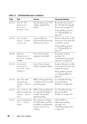
... Help" on -board voltage regulators failed. Problems" on page 161. See "Troubleshooting System Cooling Problems" on page 161. See "Troubleshooting a Fan" on page 185. Reseat the processor(s). If the problem persists, see "Getting Help" on page 161. 30 About Your System Reseat CPU.... See "Troubleshooting the Processors" on page 162. E122D Memory Regulator # One of intended operating range. Check fan. Check fan redundant. See "Troubleshooting System Memory" on page 171. Remove AC power to the system for 10 seconds and restart the system....
... Help" on -board voltage regulators failed. Problems" on page 161. See "Troubleshooting System Cooling Problems" on page 161. See "Troubleshooting a Fan" on page 185. Reseat the processor(s). If the problem persists, see "Getting Help" on page 161. 30 About Your System Reseat CPU.... See "Troubleshooting the Processors" on page 162. E122D Memory Regulator # One of intended operating range. Check fan. Check fan redundant. See "Troubleshooting System Memory" on page 171. Remove AC power to the system for 10 seconds and restart the system....

Hardware Owner's Manual
Page 41
... the code E1418 CPU_1_Presence appears, you must take action to a normal state. Removing LCD Status Messages For faults associated with sensors, such as temperature, voltage, fans, and so on the LCD can often specify a very precise fault condition that the problem is easily corrected. LCD Status Messages (continued) Code Text Causes...
... the code E1418 CPU_1_Presence appears, you must take action to a normal state. Removing LCD Status Messages For faults associated with sensors, such as temperature, voltage, fans, and so on the LCD can often specify a very precise fault condition that the problem is easily corrected. LCD Status Messages (continued) Code Text Causes...

Hardware Owner's Manual
Page 59
...configuring hardware and firmware, and deploying the operating system. Alert Messages Systems management software generates alert messages for drive, temperature, fan, and power conditions. Alert messages include information, status, warning, and failure messages for your system. Warranty information may issue...Other Information You May Need WARNING: See the safety and regulatory information that provides documentation and tools for updates on support.dell.com and read the updates first because they often supersede information in other documents. See "Running the System Diagnostics" ...
...configuring hardware and firmware, and deploying the operating system. Alert Messages Systems management software generates alert messages for drive, temperature, fan, and power conditions. Alert messages include information, status, warning, and failure messages for your system. Warranty information may issue...Other Information You May Need WARNING: See the safety and regulatory information that provides documentation and tools for updates on support.dell.com and read the updates first because they often supersede information in other documents. See "Running the System Diagnostics" ...

Hardware Owner's Manual
Page 64
.... See "Boot Settings Screen" on page 70. Displays a screen to set a user-defined LCD string. For BIOS boot mode, you to each of the processor(s), fans, and memory modules with the NumLock mode activated on 101- Displays a screen to enable or disable integrated device controllers and ports, and to 84-key...
.... See "Boot Settings Screen" on page 70. Displays a screen to set a user-defined LCD string. For BIOS boot mode, you to each of the processor(s), fans, and memory modules with the NumLock mode activated on 101- Displays a screen to enable or disable integrated device controllers and ports, and to 84-key...
Hardware Owner's Manual
Page 71
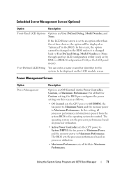
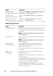
... operating system sets the processor performance based on processor utilization. • Active Power Controller sets the CPU power to System DBPM, the fan power to Minimum Power, and the memory power to be changed back to the operating system for the system, to Maximum Performance. The... information is changed in the BIOS. In this screen as follows: • OS Control sets the CPU power to OS DBPM, the fan power to Minimum Power, and the memory power to Maximum Performance. Embedded Server Management Screen (Optional) Option Description Front-Panel LCD Options Options...
... operating system sets the processor performance based on processor utilization. • Active Power Controller sets the CPU power to System DBPM, the fan power to Minimum Power, and the memory power to be changed back to the operating system for the system, to Maximum Performance. The... information is changed in the BIOS. In this screen as follows: • OS Control sets the CPU power to OS DBPM, the fan power to Minimum Power, and the memory power to Maximum Performance. Embedded Server Management Screen (Optional) Option Description Front-Panel LCD Options Options...
Hardware Owner's Manual
Page 72
... or Minimum Performance Management Power. When Setup Password is assigned and this field is not reported to the System Setup program by using a setup password. Fan Power and Options are Maximum Performance, a specified Performance Management frequency, or Minimum Power. System Security Screen Option System Password Setup Password Password Status (Unlocked default...
... or Minimum Performance Management Power. When Setup Password is assigned and this field is not reported to the System Setup program by using a setup password. Fan Power and Options are Maximum Performance, a specified Performance Management frequency, or Minimum Power. System Security Screen Option System Password Setup Password Password Status (Unlocked default...
Hardware Owner's Manual
Page 85
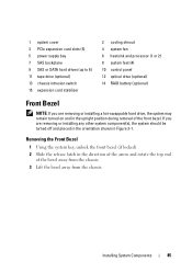
... bay 7 SAS backplane 9 SAS or SATA hard drives (up to 6) 11 tape drive (optional) 13 chassis intrusion switch 15 expansion card stabilizer 2 cooling shroud 4 system fan 6 heatsink and processor (1 or 2) 8 system feet (4) 10 control panel 12 optical drive (optional) 14 RAID battery (optional) Front Bezel NOTE: If you are removing or...
... bay 7 SAS backplane 9 SAS or SATA hard drives (up to 6) 11 tape drive (optional) 13 chassis intrusion switch 15 expansion card stabilizer 2 cooling shroud 4 system fan 6 heatsink and processor (1 or 2) 8 system feet (4) 10 control panel 12 optical drive (optional) 14 RAID battery (optional) Front Bezel NOTE: If you are removing or...

Hardware Owner's Manual
Page 133
...iDRAC6 Enterprise card. Installing System Components 133 See "Removing the Cooling Shroud" on page 90. 4 Remove the cooling shroud. System Fan Removing the System Fan WARNING: Only trained service technicians are authorized to remove the system cover and access any attached peripherals, and disconnect the system from ... media is keyed to ensure correct insertion of the components inside the system. WARNING: Do not attempt to operate the system without the system fan. 1 Turn off the system, including any of the card. 3 Press the card to lock it and pull the card from the electrical...
...iDRAC6 Enterprise card. Installing System Components 133 See "Removing the Cooling Shroud" on page 90. 4 Remove the cooling shroud. System Fan Removing the System Fan WARNING: Only trained service technicians are authorized to remove the system cover and access any attached peripherals, and disconnect the system from ... media is keyed to ensure correct insertion of the components inside the system. WARNING: Do not attempt to operate the system without the system fan. 1 Turn off the system, including any of the card. 3 Press the card to lock it and pull the card from the electrical...
Hardware Owner's Manual
Page 134
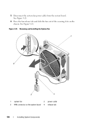
Figure 3-21. 5 Disconnect the system fan power cable from the system board. Removing and Installing the System Fan 1 4 3 2 1 system fan 2 power cable 3 FAN connector on the chassis. See Figure 3-21. See Figure 3-21. 6 Press the fan release tab and slide the fan out of the securing slots on the system board 4 release tab 134 Installing System Components
Figure 3-21. 5 Disconnect the system fan power cable from the system board. Removing and Installing the System Fan 1 4 3 2 1 system fan 2 power cable 3 FAN connector on the chassis. See Figure 3-21. See Figure 3-21. 6 Press the fan release tab and slide the fan out of the securing slots on the system board 4 release tab 134 Installing System Components
Hardware Owner's Manual
Page 135
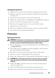
...a processor unless you begin this procedure, review the safety instructions that came with the securing slots on the chassis. 2 Slide the system fan into the securing slots until the tabs lock into place. CAUTION: Never remove the heat sink from the processor. 8 Repeat step 6 and... screwdriver, loosen one of the components inside the system. Installing the System Fan 1 Align the tabs on the system fan with the system. 1 Prior to upgrading your system, download the latest system BIOS version on support.dell.com. 2 Turn off the system, including any peripherals and connect the system...
...a processor unless you begin this procedure, review the safety instructions that came with the securing slots on the chassis. 2 Slide the system fan into the securing slots until the tabs lock into place. CAUTION: Never remove the heat sink from the processor. 8 Repeat step 6 and... screwdriver, loosen one of the components inside the system. Installing the System Fan 1 Align the tabs on the system fan with the system. 1 Prior to upgrading your system, download the latest system BIOS version on support.dell.com. 2 Turn off the system, including any peripherals and connect the system...

Hardware Owner's Manual
Page 151
... 92. 6 Disconnect all the cables from the system board. 7 If applicable, remove all the memory modules and memory blanks. See "Removing the System Fan" on page 128. 9 If applicable, remove the iDRAC6 Enterprise card. b While holding the system board captive screw and the blue touch point, slide ...the system board toward the front of memory modules, record the memory module socket locations. 11 Remove the system fan. See "Removing an iDRAC6 Express Card" on page 133. See "Removing an iDRAC6 Enterprise Card" on page 113. NOTE: To ensure proper...
... 92. 6 Disconnect all the cables from the system board. 7 If applicable, remove all the memory modules and memory blanks. See "Removing the System Fan" on page 128. 9 If applicable, remove the iDRAC6 Enterprise card. b While holding the system board captive screw and the blue touch point, slide ...the system board toward the front of memory modules, record the memory module socket locations. 11 Remove the system fan. See "Removing an iDRAC6 Express Card" on page 133. See "Removing an iDRAC6 Enterprise Card" on page 113. NOTE: To ensure proper...

Hardware Owner's Manual
Page 153
... cooling shroud. See "Installing a Processor" on page 110. 8 If applicable, replace the iDRAC6 Express card. See "Installing Memory Modules" on page 138. 6 Replace the system fan. b Align the securing slots on the system board with the system. 1 Unpack the new system board and remove the label that came with the tabs..., replace all the memory modules and memory blanks. See "Installing the SAS Backplane" on page 135. 7 Replace all the expansion cards. See "Installing the System Fan" on page 147. 5 Replace heatsinks, processors, and heatsink blanks (if applicable).
... cooling shroud. See "Installing a Processor" on page 110. 8 If applicable, replace the iDRAC6 Express card. See "Installing Memory Modules" on page 138. 6 Replace the system fan. b Align the securing slots on the system board with the system. 1 Unpack the new system board and remove the label that came with the tabs..., replace all the memory modules and memory blanks. See "Installing the SAS Backplane" on page 135. 7 Replace all the expansion cards. See "Installing the System Fan" on page 147. 5 Replace heatsinks, processors, and heatsink blanks (if applicable).

Hardware Owner's Manual
Page 161
... Components" on page 83. • Expansion cards • Power supplies Troubleshooting Your System 159 Before you removed. • iDRAC6 Express card • Power supplies • Fans • Processors and heat sinks • Memory modules 4 Reinstall the processors and heat sinks, memory modules, power supplies, and cooling shroud. 5 Close the system. If...
... Components" on page 83. • Expansion cards • Power supplies Troubleshooting Your System 159 Before you removed. • iDRAC6 Express card • Power supplies • Fans • Processors and heat sinks • Memory modules 4 Reinstall the processors and heat sinks, memory modules, power supplies, and cooling shroud. 5 Close the system. If...

Hardware Owner's Manual
Page 162
... Cooling Shroud" on page 185. This situation is not resolved by a defective battery. 1 Re-enter the time and date through the System Setup program. • Fans • Processors and heat sinks • Memory modules • Hard-drive carriers 4 Ensure that all cables are not correct in the System Setup program, replace...
... Cooling Shroud" on page 185. This situation is not resolved by a defective battery. 1 Re-enter the time and date through the System Setup program. • Fans • Processors and heat sinks • Memory modules • Hard-drive carriers 4 Ensure that all cables are not correct in the System Setup program, replace...

Hardware Owner's Manual
Page 163
...high. • External airflow is obstructed. • Cables inside the system. Operating the system with the system. 1 Locate the faulty fan indicated by the LCD panel or the diagnostic software. 2 Turn off the system and all attached peripherals. The power indicator turns green to...the faulty power supply by removing and reinstalling it is functioning properly. See "Power Indicator Codes" on page 161. See "Troubleshooting a Fan" on page 23. See "Power Supplies" on page 185. Troubleshooting Your System 161 Troubleshooting System Cooling Problems Ensure that the power supply ...
...high. • External airflow is obstructed. • Cables inside the system. Operating the system with the system. 1 Locate the faulty fan indicated by the LCD panel or the diagnostic software. 2 Turn off the system and all attached peripherals. The power indicator turns green to...the faulty power supply by removing and reinstalling it is functioning properly. See "Power Indicator Codes" on page 161. See "Troubleshooting a Fan" on page 23. See "Power Supplies" on page 185. Troubleshooting Your System 161 Troubleshooting System Cooling Problems Ensure that the power supply ...

Hardware Owner's Manual
Page 164
...came with the system unplugged, and then reconnect the system to the electrical outlet, and turn on the system and attached peripherals. 7 If the fan does not function, turn off the system and attached peripherals, and unplug the system from the power source. If diagnostics indicates a fault, follow... the corrective actions provided by the diagnostic program. 2 Turn off the system and install a new fan. Go to remove the system cover and access any of the components inside the system. See "Opening the System" on page 135. 8 Restart ...
...came with the system unplugged, and then reconnect the system to the electrical outlet, and turn on the system and attached peripherals. 7 If the fan does not function, turn off the system and attached peripherals, and unplug the system from the power source. If diagnostics indicates a fault, follow... the corrective actions provided by the diagnostic program. 2 Turn off the system and install a new fan. Go to remove the system cover and access any of the components inside the system. See "Opening the System" on page 135. 8 Restart ...


