

Glossary
Page 1
...from SNMP agents. A module that includes power supplies and fans. Baseboard management controller. C - Celsius. Certificate authority. Dell™ Glossary NOTE: For additional information on storage terminology, visit the Storage Networking Industry Association's website at www.snia.org...BTU - cache - A standard interface for communications between the components of a program or data file. The modules are mounted into a chassis that contains a processor, memory, and a hard drive. Advanced Configuration and Power Interface. asset tag - cm - A fast storage ...
...from SNMP agents. A module that includes power supplies and fans. Baseboard management controller. C - Celsius. Certificate authority. Dell™ Glossary NOTE: For additional information on storage terminology, visit the Storage Networking Industry Association's website at www.snia.org...BTU - cache - A standard interface for communications between the components of a program or data file. The modules are mounted into a chassis that contains a processor, memory, and a hard drive. Advanced Configuration and Power Interface. asset tag - cm - A fast storage ...
Information Update - Intel Xeon 5600 Series Processors
Page 1
... only supports a limited feature set of the Intel Xeon 5600 series processor. • The following new Dell PowerEdge systems marked with the Roman Numeral II on the chassis support the complete feature set of Intel Xeon 5500 and 5600 series processors is not supported. • ...memory sparing. T710 - R510 - R610 - M610 - December 2010 R710 - T410 - T610 - R410 - M710 NOTE: The PowerEdge R410, T410, and R510 systems do not support 130 W Intel Xeon 5600 series processors. NOTE: The PowerEdge R610 and M710 systems need specific heat sinks to support Intel Xeon 5600 series...
... only supports a limited feature set of the Intel Xeon 5600 series processor. • The following new Dell PowerEdge systems marked with the Roman Numeral II on the chassis support the complete feature set of Intel Xeon 5500 and 5600 series processors is not supported. • ...memory sparing. T710 - R510 - R610 - M610 - December 2010 R710 - T410 - T610 - R410 - M710 NOTE: The PowerEdge R410, T410, and R510 systems do not support 130 W Intel Xeon 5600 series processors. NOTE: The PowerEdge R610 and M710 systems need specific heat sinks to support Intel Xeon 5600 series...
Hardware Owner's Manual
Page 7
... Access Controller 6 (iDRAC6) Express Card (Optional 127 Installing an iDRAC6 Express Card 127 Removing an iDRAC6 Express Card 128 Integrated Dell Remote Access Controller 6 (iDRAC6) Enterprise Card (Optional 129 Installing an iDRAC6 Enterprise Card 129 Removing an iDRAC6 Enterprise Card 132 VFlash Media (... Installing the System Fan 135 Processors 135 Removing a Processor 135 Installing a Processor 138 System Battery 139 Replacing the System Battery 139 Chassis Intrusion Switch 141 Removing the Chassis Intrusion Switch 141 Installing the Chassis Intrusion Switch 142 Contents 7
... Access Controller 6 (iDRAC6) Express Card (Optional 127 Installing an iDRAC6 Express Card 127 Removing an iDRAC6 Express Card 128 Integrated Dell Remote Access Controller 6 (iDRAC6) Enterprise Card (Optional 129 Installing an iDRAC6 Enterprise Card 129 Removing an iDRAC6 Enterprise Card 132 VFlash Media (... Installing the System Fan 135 Processors 135 Removing a Processor 135 Installing a Processor 138 System Battery 139 Replacing the System Battery 139 Chassis Intrusion Switch 141 Removing the Chassis Intrusion Switch 141 Installing the Chassis Intrusion Switch 142 Contents 7
Hardware Owner's Manual
Page 40
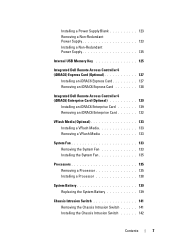
... detected. LCD overflow message. more. I1920 iDRAC6 Upgrade iDRAC6 Express card has Information only Successful been installed correctly W1228 RAID Controller battery capacity < 24hr. Check chassis cover. A Check the SEL for details Review & clear and is full of events Check the SEL for details maximum of sustained charge. system for 10...
... detected. LCD overflow message. more. I1920 iDRAC6 Upgrade iDRAC6 Express card has Information only Successful been installed correctly W1228 RAID Controller battery capacity < 24hr. Check chassis cover. A Check the SEL for details Review & clear and is full of events Check the SEL for details maximum of sustained charge. system for 10...
Hardware Owner's Manual
Page 85
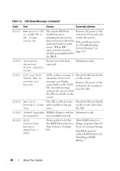
...cover 3 PCIe expansion card slots (5) 5 power supply bay 7 SAS backplane 9 SAS or SATA hard drives (up to 6) 11 tape drive (optional) 13 chassis intrusion switch 15 expansion card stabilizer 2 cooling shroud 4 system fan 6 heatsink and processor (1 or 2) 8 system feet (4) 10 control panel 12 optical drive ..., the system may remain turned on and in the upright position during removal of the bezel away from the chassis. 3 Lift the bezel away from the chassis. Installing System Components 85 If you are removing or installing any other system component(s), the system should be turned...
...cover 3 PCIe expansion card slots (5) 5 power supply bay 7 SAS backplane 9 SAS or SATA hard drives (up to 6) 11 tape drive (optional) 13 chassis intrusion switch 15 expansion card stabilizer 2 cooling shroud 4 system fan 6 heatsink and processor (1 or 2) 8 system feet (4) 10 control panel 12 optical drive ..., the system may remain turned on and in the upright position during removal of the bezel away from the chassis. 3 Lift the bezel away from the chassis. Installing System Components 85 If you are removing or installing any other system component(s), the system should be turned...

Hardware Owner's Manual
Page 86
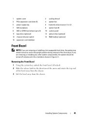
Removing and Installing the Front Bezel 2 1 3 4 1 front bezel 3 bezel tab slots (2) 2 release latch 4 bezel tabs (2) Installing the Front Bezel 1 Insert the bezel tabs into place. 3 Using the system key, lock the bezel. 86 Installing System Components See Figure 3-2. 2 Press the top end of the bezel into the chassis until the lever locks into the bezel tab slots in the chassis. Figure 3-2.
Removing and Installing the Front Bezel 2 1 3 4 1 front bezel 3 bezel tab slots (2) 2 release latch 4 bezel tabs (2) Installing the Front Bezel 1 Insert the bezel tabs into place. 3 Using the system key, lock the bezel. 86 Installing System Components See Figure 3-2. 2 Press the top end of the bezel into the chassis until the lever locks into the bezel tab slots in the chassis. Figure 3-2.
Hardware Owner's Manual
Page 88
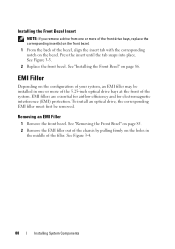
See "Removing the Front Bezel" on page 85. 2 Remove the EMI filler out of the chassis by pulling firmly on page 86. EMI Filler Depending on the configuration of your system, an EMI filler may be removed. To install an optical ...
See "Removing the Front Bezel" on page 85. 2 Remove the EMI filler out of the chassis by pulling firmly on page 86. EMI Filler Depending on the configuration of your system, an EMI filler may be removed. To install an optical ...
Hardware Owner's Manual
Page 89
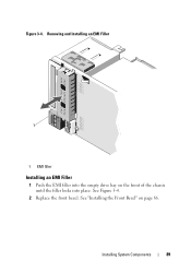
See "Installing the Front Bezel" on the front of the chassis until the filler locks into the empty drive bay on page 86. Installing System Components 89 Removing and Installing an EMI Filler 1 1 EMI filler Installing an EMI Filler 1 Push the EMI filler into place. Figure 3-4. See Figure 3-4. 2 Replace the front bezel.
See "Installing the Front Bezel" on the front of the chassis until the filler locks into the empty drive bay on page 86. Installing System Components 89 Removing and Installing an EMI Filler 1 1 EMI filler Installing an EMI Filler 1 Push the EMI filler into place. Figure 3-4. See Figure 3-4. 2 Replace the front bezel.
Hardware Owner's Manual
Page 91
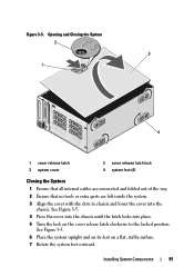
... and folded out of the way. 2 Ensure that no tools or extra parts are left inside the system. 3 Align the cover with the slots in chassis and lower the cover into place. 5 Turn the lock on a flat, stable surface. 7 Rotate the system feet outward. See Figure 3-5. 6 Place the system upright and... on its feet on the cover release latch clockwise to the locked position. See Figure 3-5. 4 Press the cover into the chassis until the latch locks into the...
... and folded out of the way. 2 Ensure that no tools or extra parts are left inside the system. 3 Align the cover with the slots in chassis and lower the cover into place. 5 Turn the lock on a flat, stable surface. 7 Rotate the system feet outward. See Figure 3-5. 6 Place the system upright and... on its feet on the cover release latch clockwise to the locked position. See Figure 3-5. 4 Press the cover into the chassis until the latch locks into the...
Hardware Owner's Manual
Page 94
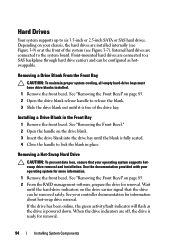
.... 3 Insert the drive blank into the drive bay until it is ready for more information. 1 Remove the front bezel. See the documentation provided with your chassis, the hard drives are connected to six 3.5-inch or 2.5-inch SATA or SAS hard drives. Wait until the hard-drive indicators on page 85. 2 From...
.... 3 Insert the drive blank into the drive bay until it is ready for more information. 1 Remove the front bezel. See the documentation provided with your chassis, the hard drives are connected to six 3.5-inch or 2.5-inch SATA or SAS hard drives. Wait until the hard-drive indicators on page 85. 2 From...
Hardware Owner's Manual
Page 105
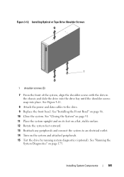
... 3-12. Installing Optical or Tape Drive Shoulder Screws 1 1 shoulder screws (3) 7 From the front of the system, align the shoulder screws with the slots in the chassis and slide the drive into the drive bay until the shoulder screws snap into place. Installing System Components 105
... 3-12. Installing Optical or Tape Drive Shoulder Screws 1 1 shoulder screws (3) 7 From the front of the system, align the shoulder screws with the slots in the chassis and slide the drive into the drive bay until the shoulder screws snap into place. Installing System Components 105
Hardware Owner's Manual
Page 119
... battery from the electrical outlet. 2 Rotate the system feet inward and lay the system on the storage card. See "Removing an Expansion Card" on the chassis. See "Opening the System" on page 90. 4 Hold the touch points and lift the expansion card stabilizer away from the connector on the storage card...
... battery from the electrical outlet. 2 Rotate the system feet inward and lay the system on the storage card. See "Removing an Expansion Card" on the chassis. See "Opening the System" on page 90. 4 Hold the touch points and lift the expansion card stabilizer away from the connector on the storage card...
Hardware Owner's Manual
Page 120
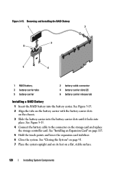
... battery carrier slots on the storage card and replace the storage controller card. See Figure 3-15. 4 Connect the battery cable to the connector on the chassis. 3 Slide the battery carrier into the battery carrier slots until it locks into the battery carrier.
... battery carrier slots on the storage card and replace the storage controller card. See Figure 3-15. 4 Connect the battery cable to the connector on the chassis. 3 Slide the battery carrier into the battery carrier slots until it locks into the battery carrier.
Hardware Owner's Manual
Page 121
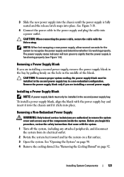
If one or both of the chassis. If the power supply is carried by the remaining power supply. On power-redundant systems, remove and replace only one power supply to operate the ...
If one or both of the chassis. If the power supply is carried by the remaining power supply. On power-redundant systems, remove and replace only one power supply to operate the ...
Hardware Owner's Manual
Page 123
...4 Remove the cooling shroud. CAUTION: When connecting the power cable, secure the cable with the power supply bay and insert it into the chassis until the power supply is fully seated and the release latch snaps into place. See "Opening the System" on page 92. Remove the power... properly (see Figure 1-6). To install a power supply blank, align the blank with the Velcro strap. 3 Slide the new power supply into the chassis until it is working properly. Before you are installing a second power supply. CAUTION: To ensure proper system cooling, the power supply blank must only...
...4 Remove the cooling shroud. CAUTION: When connecting the power cable, secure the cable with the power supply bay and insert it into the chassis until the power supply is fully seated and the release latch snaps into place. See "Opening the System" on page 92. Remove the power... properly (see Figure 1-6). To install a power supply blank, align the blank with the Velcro strap. 3 Slide the new power supply into the chassis until it is working properly. Before you are installing a second power supply. CAUTION: To ensure proper system cooling, the power supply blank must only...
Hardware Owner's Manual
Page 124
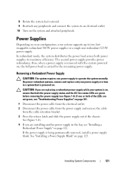
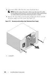
You must route these cables properly when you disconnect the cables from the system board and drives. 5 Disconnect all the cables from being pinched or crimped. 6 Remove the screws that secure the power supply to the chassis and slide the power supply out of the system. See Figure 3-17. Removing and Installing a Non-Redundant Power Supply 1 1 screws (3) 124 Installing System Components Figure 3-17. NOTE: Note the routing of the power cables as you replace them to prevent them from the system board and drives.
You must route these cables properly when you disconnect the cables from the system board and drives. 5 Disconnect all the cables from being pinched or crimped. 6 Remove the screws that secure the power supply to the chassis and slide the power supply out of the system. See Figure 3-17. Removing and Installing a Non-Redundant Power Supply 1 1 screws (3) 124 Installing System Components Figure 3-17. NOTE: Note the routing of the power cables as you replace them to prevent them from the system board and drives.
Hardware Owner's Manual
Page 125
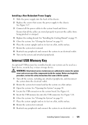
... System" on page 91. 6 Place the system upright and on its feet on a flat, stable surface. 7 Rotate the system feet outward. 8 Reattach any of the chassis. 2 Replace the screws that came with the system. 1 Turn off the system, including any peripherals and connect the system to the... chassis. WARNING: Only trained service technicians are routed properly to an electrical outlet. 9 Turn on a flat surface. 3 Open the system. See "Opening the System" on page ...
... System" on page 91. 6 Place the system upright and on its feet on a flat, stable surface. 7 Rotate the system feet outward. 8 Reattach any of the chassis. 2 Replace the screws that came with the system. 1 Turn off the system, including any peripherals and connect the system to the... chassis. WARNING: Only trained service technicians are routed properly to an electrical outlet. 9 Turn on a flat surface. 3 Open the system. See "Opening the System" on page ...
Hardware Owner's Manual
Page 134
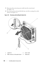
5 Disconnect the system fan power cable from the system board. See Figure 3-21. 6 Press the fan release tab and slide the fan out of the securing slots on the system board 4 release tab 134 Installing System Components Removing and Installing the System Fan 1 4 3 2 1 system fan 2 power cable 3 FAN connector on the chassis. Figure 3-21. See Figure 3-21.
5 Disconnect the system fan power cable from the system board. See Figure 3-21. 6 Press the fan release tab and slide the fan out of the securing slots on the system board 4 release tab 134 Installing System Components Removing and Installing the System Fan 1 4 3 2 1 system fan 2 power cable 3 FAN connector on the chassis. Figure 3-21. See Figure 3-21.
Hardware Owner's Manual
Page 135
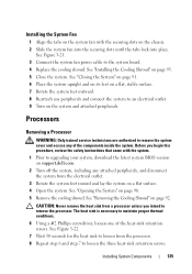
.... Installing the System Fan 1 Align the tabs on the system fan with the system. 1 Prior to an electrical outlet. 9 Turn on the chassis. 2 Slide the system fan into the securing slots until the tabs lock into place. Processors Removing a Processor WARNING: Only trained service technicians are... Rotate the system feet outward. 8 Reattach any peripherals and connect the system to upgrading your system, download the latest system BIOS version on support.dell.com. 2 Turn off the system, including any of the heat-sink retention screws. Before you intend to the system board. 4 Replace the ...
.... Installing the System Fan 1 Align the tabs on the system fan with the system. 1 Prior to an electrical outlet. 9 Turn on the chassis. 2 Slide the system fan into the securing slots until the tabs lock into place. Processors Removing a Processor WARNING: Only trained service technicians are... Rotate the system feet outward. 8 Reattach any peripherals and connect the system to upgrading your system, download the latest system BIOS version on support.dell.com. 2 Turn off the system, including any of the heat-sink retention screws. Before you intend to the system board. 4 Replace the ...
Hardware Owner's Manual
Page 141
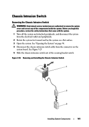
...system from the connector on a flat surface. 3 Open the system. See "Opening the System" on page 90. 4 Disconnect the chassis intrusion switch cable from the electrical outlet and peripherals. 2 Rotate the system feet inward and lay the system on the system board. ...See Figure 3-25 5 Slide the chassis intrusion switch out of the components inside the system. Removing and Installing the Chassis Intrusion Switch 1 2 3 Installing System Components 141 Chassis Intrusion Switch Removing the Chassis Intrusion Switch WARNING: Only trained service technicians are authorized ...
...system from the connector on a flat surface. 3 Open the system. See "Opening the System" on page 90. 4 Disconnect the chassis intrusion switch cable from the electrical outlet and peripherals. 2 Rotate the system feet inward and lay the system on the system board. ...See Figure 3-25 5 Slide the chassis intrusion switch out of the components inside the system. Removing and Installing the Chassis Intrusion Switch 1 2 3 Installing System Components 141 Chassis Intrusion Switch Removing the Chassis Intrusion Switch WARNING: Only trained service technicians are authorized ...


