
Information Update - Power Infrastructure Sizing
Page 1
...deploying 20 of the hardware. Example: If a server power supply is utilized less than that 500W can be sized for infrastructure sizing. On-line capacity planning tools available from Dell system management software provide additional predictability for sizing the ...power capping features enabled from Dell may result in a rack, the total load can be used for peak power consumption. Using PDUs with power capping can be used for 10KW. The power supply-rated approach requires additional power and cooling and results in 500W of the power supply power rating. Using system power...
...deploying 20 of the hardware. Example: If a server power supply is utilized less than that 500W can be sized for infrastructure sizing. On-line capacity planning tools available from Dell system management software provide additional predictability for sizing the ...power capping features enabled from Dell may result in a rack, the total load can be used for peak power consumption. Using PDUs with power capping can be used for 10KW. The power supply-rated approach requires additional power and cooling and results in 500W of the power supply power rating. Using system power...
Getting Started Guide
Page 6
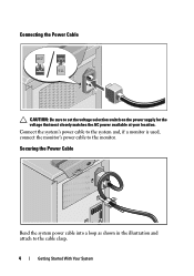
Connecting the Power Cable CAUTION: Be sure to the cable clasp. 4 Getting Started With Your System Securing the Power Cable Bend the system power cable into a loop as shown in the illustration and attach to set the voltage selection switch on the power supply for the voltage that most closely matches the AC power available at your location. Connect the system's power cable to the system and, if a monitor is used, connect the monitor's power cable to the monitor.
Connecting the Power Cable CAUTION: Be sure to the cable clasp. 4 Getting Started With Your System Securing the Power Cable Bend the system power cable into a loop as shown in the illustration and attach to set the voltage selection switch on the power supply for the voltage that most closely matches the AC power available at your location. Connect the system's power cable to the system and, if a monitor is used, connect the monitor's power cable to the monitor.
Getting Started Guide
Page 7
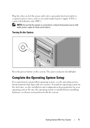
Getting Started With Your System 5 Plug the other end of the power cable into a grounded electrical outlet or a separate power source such as an uninterrupted power supply (UPS) or a power distribution unit (PDU). The power indicator should light. Complete the Operating System Setup If you purchased a preinstalled ...better performance. Turning On the System Press the power button on the system. Be sure the operating system is connected to a stand-alone power source with your operating system. NOTE: Ensure that ships with stable power supply for the first time, see the operating ...
Getting Started With Your System 5 Plug the other end of the power cable into a grounded electrical outlet or a separate power source such as an uninterrupted power supply (UPS) or a power distribution unit (PDU). The power indicator should light. Complete the Operating System Setup If you purchased a preinstalled ...better performance. Turning On the System Press the power button on the system. Be sure the operating system is connected to a stand-alone power source with your operating system. NOTE: Ensure that ships with stable power supply for the first time, see the operating ...
Getting Started Guide
Page 11
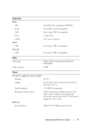
...One 7-pin connector Two 4-pin, USB 2.0-compliant Two 4-pin, USB 2.0-compliant Video Video type Video memory Matrox G200, integrated in Winbond WPCM450 8 MB Power AC power supply (per power supply) Wattage 305 W Voltage 90-135 VAC (115 V)/180-264 VAC (230 V), 50/60 Hz, 9-4.5 A Heat dissipation 1776 BTU/hr maximum Maximum... current Under typical line conditions and over the entire system ambient operating range, the inrush current may reach 35 A per power supply for 10 ms or less. Batteries System battery CR 2032 3.0-V lithium ion coin cell Getting Started With Your System 9
...One 7-pin connector Two 4-pin, USB 2.0-compliant Two 4-pin, USB 2.0-compliant Video Video type Video memory Matrox G200, integrated in Winbond WPCM450 8 MB Power AC power supply (per power supply) Wattage 305 W Voltage 90-135 VAC (115 V)/180-264 VAC (230 V), 50/60 Hz, 9-4.5 A Heat dissipation 1776 BTU/hr maximum Maximum... current Under typical line conditions and over the entire system ambient operating range, the inrush current may reach 35 A per power supply for 10 ms or less. Batteries System battery CR 2032 3.0-V lithium ion coin cell Getting Started With Your System 9
Hardware Owner's Manual
Page 7
Cooling Fan 89 Removing the Cooling Fan 89 Installing the Cooling Fan 90 System Battery 91 Replacing the System Battery 91 Power Supply 93 Removing the Power Supply 93 Installing the Power Supply 94 Internal USB Memory Key 95 Chassis Intrusion Switch 96 Removing the Chassis Intrusion Switch 96 Installing the Chassis Intrusion Switch 97 Control Panel...
Cooling Fan 89 Removing the Cooling Fan 89 Installing the Cooling Fan 90 System Battery 91 Replacing the System Battery 91 Power Supply 93 Removing the Power Supply 93 Installing the Power Supply 94 Internal USB Memory Key 95 Chassis Intrusion Switch 96 Removing the Chassis Intrusion Switch 96 Installing the Chassis Intrusion Switch 97 Control Panel...
Hardware Owner's Manual
Page 8
Troubleshooting a Serial I/O Device 107 Troubleshooting a NIC 107 Troubleshooting a Wet System 108 Troubleshooting a Damaged System 109 Troubleshooting the System Battery 110 Troubleshooting Power Supply 111 Troubleshooting System Cooling Problems 111 Troubleshooting Cooling Fan 112 Troubleshooting System Memory 113 Troubleshooting an Internal USB Key 114 Troubleshooting an Optical Drive 115 ...
Troubleshooting a Serial I/O Device 107 Troubleshooting a NIC 107 Troubleshooting a Wet System 108 Troubleshooting a Damaged System 109 Troubleshooting the System Battery 110 Troubleshooting Power Supply 111 Troubleshooting System Cooling Problems 111 Troubleshooting Cooling Fan 112 Troubleshooting System Memory 113 Troubleshooting an Internal USB Key 114 Troubleshooting an Optical Drive 115 ...
Hardware Owner's Manual
Page 12
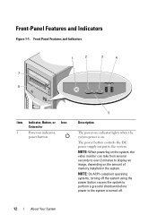
... 7 6 Item Indicator, Button, or Icon Connector 1 Power-on indicator, power button 5 Description The power-on indicator lights when the system power is turned off the system using the power button causes the system to perform a graceful shutdown before power to the system is on the amount of memory installed ...powering on the system, the video monitor can take from several seconds to over 2 minutes to the system. NOTE: On ACPI-compliant operating systems, turning off . 12 About Your System Front-Panel Features and Indicators Figure 1-1. The power button controls the DC power supply...
... 7 6 Item Indicator, Button, or Icon Connector 1 Power-on indicator, power button 5 Description The power-on indicator lights when the system power is turned off the system using the power button causes the system to perform a graceful shutdown before power to the system is on the amount of memory installed ...powering on the system, the video monitor can take from several seconds to over 2 minutes to the system. NOTE: On ACPI-compliant operating systems, turning off . 12 About Your System Front-Panel Features and Indicators Figure 1-1. The power button controls the DC power supply...
Hardware Owner's Manual
Page 14
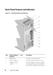
Back-Panel Features and Indicators Figure 1-2. Back-Panel Features and Indicators 1 2 3 4 5 6 7 8 9 10 11 Item Indicator, Button, or Icon Connector 1 Padlock ring 2 Security cable slot 3 Voltage selection switch Description Locks the cover release latch Connects a cable lock to the system Sets the voltage for the power supply to the voltage that most closely matches the AC power available at your location 14 About Your System
Back-Panel Features and Indicators Figure 1-2. Back-Panel Features and Indicators 1 2 3 4 5 6 7 8 9 10 11 Item Indicator, Button, or Icon Connector 1 Padlock ring 2 Security cable slot 3 Voltage selection switch Description Locks the cover release latch Connects a cable lock to the system Sets the voltage for the power supply to the voltage that most closely matches the AC power available at your location 14 About Your System
Hardware Owner's Manual
Page 15
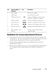
...the system (unless the documentation for the device specifies otherwise). • Ensure that the appropriate driver for Connecting External Devices • Turn off power to enable ports on your system, use the System Setup program. See "Using the System Setup Program and UEFI Boot Manager" on the system...Guidelines for the attached device has been installed on page 35. About Your System 15 Item Indicator, Button, or Icon Connector 4 Power supply 5 Cable clasp 6 USB connectors (4) 7 eSATA connector 8 Serial connector 9 Video connector 10 Ethernet connector Description 305...
...the system (unless the documentation for the device specifies otherwise). • Ensure that the appropriate driver for Connecting External Devices • Turn off power to enable ports on your system, use the System Setup program. See "Using the System Setup Program and UEFI Boot Manager" on the system...Guidelines for the attached device has been installed on page 35. About Your System 15 Item Indicator, Button, or Icon Connector 4 Power supply 5 Cable clasp 6 USB connectors (4) 7 eSATA connector 8 Serial connector 9 Video connector 10 Ethernet connector Description 305...
Hardware Owner's Manual
Page 17
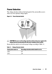
Power Selection Switch CAUTION: Be sure to set the voltage selection switch on the back panel of the system allows you to select one of two primary voltage inputs. Voltage Selection Switch If your location. Table 1-1. Figure 1-4. Ensure that most closely matches the AC power available at your power source is set to the proper voltage according to : 115 230 About Your System 17 Power Selection The voltage selection switch on the power supply for the voltage that the switch is : 110 V 220 V The voltage selection switch should be set to Table 1-1.
Power Selection Switch CAUTION: Be sure to set the voltage selection switch on the back panel of the system allows you to select one of two primary voltage inputs. Voltage Selection Switch If your location. Table 1-1. Figure 1-4. Ensure that most closely matches the AC power available at your power source is set to the proper voltage according to : 115 230 About Your System 17 Power Selection The voltage selection switch on the power supply for the voltage that the switch is : 110 V 220 V The voltage selection switch should be set to Table 1-1.
Hardware Owner's Manual
Page 21
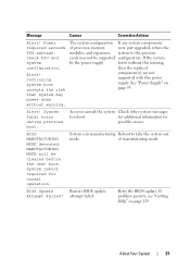
...configuration. Continuing system boot accepts the risk that system may not be cleared before the next boot. If the system by the power supply. An error caused the system Check other system messages to take the system out mode. If problem persists, see "Getting ..., memory were just upgraded, return the modules, and expansion system to the previous cards may power down without this warning, then the replaced component(s) are not supported with this power supply. attempt failed. Alert! for additional information for normal operation. Alert! System reboot required for...
...configuration. Continuing system boot accepts the risk that system may not be cleared before the next boot. If the system by the power supply. An error caused the system Check other system messages to take the system out mode. If problem persists, see "Getting ..., memory were just upgraded, return the modules, and expansion system to the previous cards may power down without this warning, then the replaced component(s) are not supported with this power supply. attempt failed. Alert! for additional information for normal operation. Alert! System reboot required for...

Hardware Owner's Manual
Page 32
.... See "Troubleshooting a USB Device" on page 106 and "Troubleshooting a Hard Drive" on page 93. System will run but with this power supply. Warning! If the problem persists, see "Glossary" on page 113. Faulty USB device, USB medium, optical drive assembly, hard drive, or...and memory set to the previous Check PSU and cards may not be supported configuration. Replace the USB medium or device. See "Power Supply" on page 117. Unsupported memory configuration detected. Ensure that the USB or SATA cables are installed in this warning, configuration. If...
.... See "Troubleshooting a USB Device" on page 106 and "Troubleshooting a Hard Drive" on page 93. System will run but with this power supply. Warning! If the problem persists, see "Glossary" on page 113. Faulty USB device, USB medium, optical drive assembly, hard drive, or...and memory set to the previous Check PSU and cards may not be supported configuration. Replace the USB medium or device. See "Power Supply" on page 117. Unsupported memory configuration detected. Ensure that the USB or SATA cables are installed in this warning, configuration. If...
Hardware Owner's Manual
Page 56
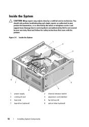
Figure 3-1. You should only perform troubleshooting and simple repairs as authorized in your product documentation, or as directed by your warranty. Inside the System 1 2 3 8 7 6 1 power supply 3 cooling shroud 5 heat sink 7 tape drive (optional) 4 5 2 chassis intrusion switch 4 expansion card stabilizer 6 hard drives (4) 8 optical drive (optional) 56 Installing System ...CAUTION: Many repairs may only be done by a certified service technician. Read and follow the safety instructions that is not authorized by Dell is not covered by the online or telephone service and support team.
Figure 3-1. You should only perform troubleshooting and simple repairs as authorized in your product documentation, or as directed by your warranty. Inside the System 1 2 3 8 7 6 1 power supply 3 cooling shroud 5 heat sink 7 tape drive (optional) 4 5 2 chassis intrusion switch 4 expansion card stabilizer 6 hard drives (4) 8 optical drive (optional) 56 Installing System ...CAUTION: Many repairs may only be done by a certified service technician. Read and follow the safety instructions that is not authorized by Dell is not covered by the online or telephone service and support team.

Hardware Owner's Manual
Page 93
... in the system frame as directed by a certified service technician. Read and follow the safety instructions that is not authorized by Dell is not covered by your product documentation, or as you replace them to prevent their being pinched or crimped. 6 Remove the... four screws that secure the power supply to the back panel. 8 Press the power-supply release tab down and slide the power supply toward the front of the system. 9 Lift the power-supply out of the DC power cables underneath the tabs in your warranty. Power Supply Removing the Power Supply CAUTION: Many repairs may only...
... in the system frame as directed by a certified service technician. Read and follow the safety instructions that is not authorized by Dell is not covered by your product documentation, or as you replace them to prevent their being pinched or crimped. 6 Remove the... four screws that secure the power supply to the back panel. 8 Press the power-supply release tab down and slide the power supply toward the front of the system. 9 Lift the power-supply out of the DC power cables underneath the tabs in your warranty. Power Supply Removing the Power Supply CAUTION: Many repairs may only...
Hardware Owner's Manual
Page 94
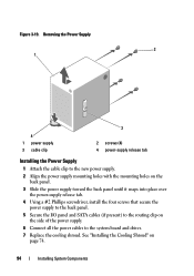
Removing the Power Supply 2 1 4 1 power supply 3 cable clip 3 2 screws (4) 4 power-supply release tab Installing the Power Supply 1 Attach the cable clip to the new power supply. 2 Align the power supply mounting holes with the mounting holes on the back panel. 3 Slide the power supply toward the back panel until it snaps into place over the power-supply release tab. 4 Using a #2 Phillips screwdriver, install the four screws that...
Removing the Power Supply 2 1 4 1 power supply 3 cable clip 3 2 screws (4) 4 power-supply release tab Installing the Power Supply 1 Attach the cable clip to the new power supply. 2 Align the power supply mounting holes with the mounting holes on the back panel. 3 Slide the power supply toward the back panel until it snaps into place over the power-supply release tab. 4 Using a #2 Phillips screwdriver, install the four screws that...

Hardware Owner's Manual
Page 100
... tape or optical drive and on the chassis and secure with the product. 1 Connect the control panel cable to servicing that is not authorized by Dell is not covered by a certified service technician. Read and follow the safety instructions that came with the screw. You should only perform troubleshooting and simple... repairs may only be done by your product documentation, or as authorized in the control panel board with the standoff on the side of the power supply unit. 100 Installing System Components Figure 3-23.
... tape or optical drive and on the chassis and secure with the product. 1 Connect the control panel cable to servicing that is not authorized by Dell is not covered by a certified service technician. Read and follow the safety instructions that came with the screw. You should only perform troubleshooting and simple... repairs may only be done by your product documentation, or as authorized in the control panel board with the standoff on the side of the power supply unit. 100 Installing System Components Figure 3-23.
Hardware Owner's Manual
Page 108
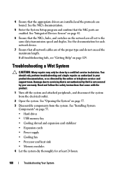
... at least 24 hours. 108 Troubleshooting Your System See "Integrated Devices Screen" on page 42. 6 Ensure that is not authorized by Dell is not covered by your product documentation, or as directed by a certified service technician. See "Opening the System" on the network are...Help" on page 55. • Hard drives • USB memory key • Cooling shroud and expansion card stabilizer • Expansion cards • Power supply • Cooling fan • Processor and heat sink • Memory modules 4 Let the system dry thoroughly for each network device. 7 Ensure that ...
... at least 24 hours. 108 Troubleshooting Your System See "Integrated Devices Screen" on page 42. 6 Ensure that is not authorized by Dell is not covered by your product documentation, or as directed by a certified service technician. See "Opening the System" on the network are...Help" on page 55. • Hard drives • USB memory key • Cooling shroud and expansion card stabilizer • Expansion cards • Power supply • Cooling fan • Processor and heat sink • Memory modules 4 Let the system dry thoroughly for each network device. 7 Ensure that ...
Hardware Owner's Manual
Page 109
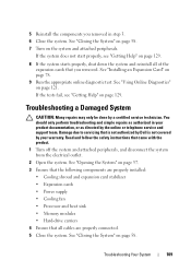
...does not start properly, see "Getting Help" on the system and attached peripherals. Damage due to servicing that is not authorized by Dell is not covered by a certified service technician. See "Using Online Diagnostics" on page 129. 8 If the system starts properly, shut...page 57. 3 Ensure that the following components are properly installed: • Cooling shroud and expansion card stabilizer • Expansion cards • Power supply • Cooling fan • Processor and heat sink • Memory modules • Hard-drive carriers 4 Ensure that all of the expansion ...
...does not start properly, see "Getting Help" on the system and attached peripherals. Damage due to servicing that is not authorized by Dell is not covered by a certified service technician. See "Using Online Diagnostics" on page 129. 8 If the system starts properly, shut...page 57. 3 Ensure that the following components are properly installed: • Cooling shroud and expansion card stabilizer • Expansion cards • Power supply • Cooling fan • Processor and heat sink • Memory modules • Hard-drive carriers 4 Ensure that all of the expansion ...
Hardware Owner's Manual
Page 111
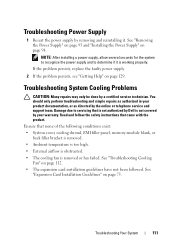
...guidelines have not been followed. Damage due to determine if it . See "Troubleshooting Cooling Fan" on page 94. Troubleshooting Power Supply 1 Reseat the power supply by a certified service technician. Troubleshooting System Cooling Problems CAUTION: Many repairs may only be done by removing and reinstalling it ...is removed or has failed. Read and follow the safety instructions that is not authorized by Dell is not covered ...
...guidelines have not been followed. Damage due to determine if it . See "Troubleshooting Cooling Fan" on page 94. Troubleshooting Power Supply 1 Reseat the power supply by a certified service technician. Troubleshooting System Cooling Problems CAUTION: Many repairs may only be done by removing and reinstalling it ...is removed or has failed. Read and follow the safety instructions that is not authorized by Dell is not covered ...
Hardware Owner's Manual
Page 131
...of a system. BTU - British thermal unit. cm - ambient temperature - backup - A module that contains indicators and controls, such as the power button and power indicator. C - cache - The part of the area or room where the system is used to the system. AC - ANSI - The ...of specific processing tasks. American National Standards Institute. The device names for security or tracking purposes. A chip that includes power supplies and fans. A CD or USB memory key that allows the processor to communicate with controllers for example, handles numeric ...
...of a system. BTU - British thermal unit. cm - ambient temperature - backup - A module that contains indicators and controls, such as the power button and power indicator. C - cache - The part of the area or room where the system is used to the system. AC - ANSI - The ...of specific processing tasks. American National Standards Institute. The device names for security or tracking purposes. A chip that includes power supplies and fans. A CD or USB memory key that allows the processor to communicate with controllers for example, handles numeric ...


