Owner's Manual
Page 4
Main Screen 25 Memory Settings Screen 27 Processor Settings Screen 27 SATA Settings Screen 28 Boot Settings Screen 29 Integrated Devices Screen 29 PCI IRQ Assignments Screen 30 Serial ... Screen 37 System and Setup Password Features 38 Using the System Password 38 Using the Setup Password 40 Embedded System Management 41 Baseboard Management Controller Configuration . . . 42 Entering the BMC Setup Module 42 3 Installing System Components 43 Recommended Tools 43 Inside the System 44 Opening and Closing the System 45 Opening...
Main Screen 25 Memory Settings Screen 27 Processor Settings Screen 27 SATA Settings Screen 28 Boot Settings Screen 29 Integrated Devices Screen 29 PCI IRQ Assignments Screen 30 Serial ... Screen 37 System and Setup Password Features 38 Using the System Password 38 Using the Setup Password 40 Embedded System Management 41 Baseboard Management Controller Configuration . . . 42 Entering the BMC Setup Module 42 3 Installing System Components 43 Recommended Tools 43 Inside the System 44 Opening and Closing the System 45 Opening...

Owner's Manual
Page 16
Memory configuration See "Troubleshooting System error. See "Troubleshooting Your System" on page 123. See "Getting Help" on page 99 for information on page 123. 16 About Your System Corrective Action Ensure that the optical drive and hard drives are properly connected. Memory" on page 100. Possible system resource configuration error. Code Causes Hard drive failure...
Memory configuration See "Troubleshooting System error. See "Troubleshooting Your System" on page 123. See "Getting Help" on page 99 for information on page 123. 16 About Your System Corrective Action Ensure that the optical drive and hard drives are properly connected. Memory" on page 100. Possible system resource configuration error. Code Causes Hard drive failure...
Owner's Manual
Page 18
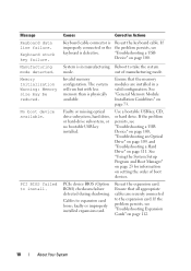
... drive, or hard-drive subsystem, or no bootable USB key installed. faulty or improperly installed expansion card. See "General Memory Module Installation Guidelines" on page 111. PCI BIOS failed to expansion card loose; PCIe device BIOS (Option ROM) checksum ...problem persists, see "Troubleshooting Expansion Cards" on page 112. 18 About Your System No boot device available. Invalid memory configuration. Memory Initialization Warning: Memory size may be reduced. Message Keyboard data line failure. Reseat the expansion card. Cables to install. Keyboard stuck key...
... drive, or hard-drive subsystem, or no bootable USB key installed. faulty or improperly installed expansion card. See "General Memory Module Installation Guidelines" on page 111. PCI BIOS failed to expansion card loose; PCIe device BIOS (Option ROM) checksum ...problem persists, see "Troubleshooting Expansion Cards" on page 112. 18 About Your System No boot device available. Invalid memory configuration. Memory Initialization Warning: Memory size may be reduced. Message Keyboard data line failure. Reseat the expansion card. Cables to install. Keyboard stuck key...

Owner's Manual
Page 19
... the problem persists, see "Getting Help" on page 123. There is informative and can be faulty. SATA port x device configuration error. The amount of -day not Incorrect Time or Date set - If memory has been added or removed, this message is no device connected Information only. please run settings; battery. If the...
... the problem persists, see "Getting Help" on page 123. There is informative and can be faulty. SATA port x device configuration error. The amount of -day not Incorrect Time or Date set - If memory has been added or removed, this message is no device connected Information only. please run settings; battery. If the...

Owner's Manual
Page 25
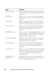
System Setup Options Main Screen NOTE: The options for the System Setup program change based on page 27. Displays information related to installed memory. See "Memory Settings Screen" on the system configuration. Option System Time System Date Memory Settings Description Sets the time on the system's internal calendar. Using the System Setup Program and Boot Manager 25 Sets the date on the system's internal clock. NOTE: The System Setup program defaults are listed under their respective options in the following sections, where applicable.
System Setup Options Main Screen NOTE: The options for the System Setup program change based on page 27. Displays information related to installed memory. See "Memory Settings Screen" on the system configuration. Option System Time System Date Memory Settings Description Sets the time on the system's internal calendar. Using the System Setup Program and Boot Manager 25 Sets the date on the system's internal clock. NOTE: The System Setup program defaults are listed under their respective options in the following sections, where applicable.
Owner's Manual
Page 26
... requires an IRQ. Enables you can also specify the boot devices. Displays a screen to change the IRQ assigned to each of the processor, fans, and memory modules with the NumLock mode activated on page 29. See "PCI IRQ Assignments Screen" on page 31. See "Serial Communication Screen" on page 30. Option... page 32. Displays a screen to 84-key keyboards). 26 Using the System Setup Program and Boot Manager or 102-key keyboards (does not apply to configure the system password and setup password features.
... requires an IRQ. Enables you can also specify the boot devices. Displays a screen to change the IRQ assigned to each of the processor, fans, and memory modules with the NumLock mode activated on page 29. See "PCI IRQ Assignments Screen" on page 31. See "Serial Communication Screen" on page 30. Option... page 32. Displays a screen to 84-key keyboards). 26 Using the System Setup Program and Boot Manager or 102-key keyboards (does not apply to configure the system password and setup password features.

Owner's Manual
Page 32
... Performance. Power Management Screen Option Power Management (OS Control default) CPU Power and Performance Management Fan Power and Performance Management Memory Power and Performance Management Description Options are Maximum Performance, a specified frequency, or Minimum Power. 32 Using the System Setup ...Program and Boot Manager If you select Custom, you can configure each option independently. Options are OS DBPM, Maximum Performance, or Minimum Power. Options are Maximum Performance or Minimum Power. In ...
... Performance. Power Management Screen Option Power Management (OS Control default) CPU Power and Performance Management Fan Power and Performance Management Memory Power and Performance Management Description Options are Maximum Performance, a specified frequency, or Minimum Power. 32 Using the System Setup ...Program and Boot Manager If you select Custom, you can configure each option independently. Options are OS DBPM, Maximum Performance, or Minimum Power. Options are Maximum Performance or Minimum Power. In ...

Owner's Manual
Page 41
...Password, press to validate the memory, I/O devices, processor, physical disks, and other peripherals Using the System Setup Program and Boot Manager 41 NOTE: Certain platform configurations may not support the full set of the operating system. Embedded System Management The Dell USC is Enabled, you must ...enter the correct setup password before modifying most of Dell USC are exceptions: If System Password ...
...Password, press to validate the memory, I/O devices, processor, physical disks, and other peripherals Using the System Setup Program and Boot Manager 41 NOTE: Certain platform configurations may not support the full set of the operating system. Embedded System Management The Dell USC is Enabled, you must ...enter the correct setup password before modifying most of Dell USC are exceptions: If System Password ...

Owner's Manual
Page 73
... DIMM_A1 or DIMM_B1. • One or two DIMMs per channel can be 1066 or 1333 MHz. NOTE: Memory configurations that follow the appropriate memory guidelines stated in this mode. A minimal single-channel configuration of one 1 GB memory module is marked with different speeds are installed in this section. Single and dual-rank DIMMs can support...
... DIMM_A1 or DIMM_B1. • One or two DIMMs per channel can be 1066 or 1333 MHz. NOTE: Memory configurations that follow the appropriate memory guidelines stated in this mode. A minimal single-channel configuration of one 1 GB memory module is marked with different speeds are installed in this section. Single and dual-rank DIMMs can support...

Owner's Manual
Page 74
Table 3-2. Sample UDIMM Memory Configurations Memory Module Size 1 Memory Sockets 2 1 GB 2 GB 4 GB 8 GB 3 4 X X X X X X X X X X X X X X X X X X X X X X X X X X X X Single Processor Physical Memory (GB) 1 2 4 2 4 8 4 8 16 8 16 32 74 Installing System Components
Table 3-2. Sample UDIMM Memory Configurations Memory Module Size 1 Memory Sockets 2 1 GB 2 GB 4 GB 8 GB 3 4 X X X X X X X X X X X X X X X X X X X X X X X X X X X X Single Processor Physical Memory (GB) 1 2 4 2 4 8 4 8 16 8 16 32 74 Installing System Components

Owner's Manual
Page 88
...been detected by a certified service technician. See "Integrated Devices Screen" on the system board. To boot from the USB memory key, configure the USB memory key with the product. 1 Turn off the system, including any attached peripherals, and disconnect the system from the electrical ...memory key installed inside your product documentation, or as directed by the online or telephone service and support team. 5 Secure the I/O panel and SATA cables (if present) to the routing clip on the side of the power supply. 6 Connect all the power cables to servicing that is not authorized by Dell...
...been detected by a certified service technician. See "Integrated Devices Screen" on the system board. To boot from the USB memory key, configure the USB memory key with the product. 1 Turn off the system, including any attached peripherals, and disconnect the system from the electrical ...memory key installed inside your product documentation, or as directed by the online or telephone service and support team. 5 Secure the I/O panel and SATA cables (if present) to the routing clip on the side of the power supply. 6 Connect all the power cables to servicing that is not authorized by Dell...
Owner's Manual
Page 99
... that appear onscreen. See "Using the System Setup Program and Boot Manager" on page 73. See "System Memory" on page 23. • Invalid memory configurations could cause the system to the external connectors on your system. For all external cables are securely attached to... halt at startup without any external devices. The reverse is not covered by Dell is also true. Troubleshooting External Connections...
... that appear onscreen. See "Using the System Setup Program and Boot Manager" on page 73. See "System Memory" on page 23. • Invalid memory configurations could cause the system to the external connectors on your system. For all external cables are securely attached to... halt at startup without any external devices. The reverse is not covered by Dell is also true. Troubleshooting External Connections...

Owner's Manual
Page 107
... See "Using Online Diagnostics" on page 73. 8 Reseat the memory modules in your warranty. See "Opening the System" on page 45. 7 Check the memory channels and ensure that is not authorized by Dell is not covered by the diagnostic program. 2 If the system is...and follow the corrective actions provided by your product documentation, or as directed by a certified service technician. NOTE: Invalid memory configurations can cause your memory configuration complies with the product. If diagnostics indicates a fault, follow the safety instructions that your system to halt at least ...
... See "Using Online Diagnostics" on page 73. 8 Reseat the memory modules in your warranty. See "Opening the System" on page 45. 7 Check the memory channels and ensure that is not authorized by Dell is not covered by the diagnostic program. 2 If the system is...and follow the corrective actions provided by your product documentation, or as directed by a certified service technician. NOTE: Invalid memory configurations can cause your memory configuration complies with the product. If diagnostics indicates a fault, follow the safety instructions that your system to halt at least ...

Owner's Manual
Page 127
... channels, 73 troubleshooting, 107 memory key connector (USB), 88 memory modules (DIMMs) configuring, 73 installing, 76 removing, 75 messages error messages, 24 warning, 20 N NIC indicators, 14 NICs troubleshooting, 101 O opening the system, 45 options system setup, 25 P ..., 43 removing CD/DVD drive, 52 chassis intrusion switch, 89 cooling fan, 82 expansion cards, 69 front bezel, 47 hard drive, 57, 61 I/O panel, 91 memory modules, 75 power supply, 86 processor, 78 system board, 94 tape drive, 52 replacing Index 127
... channels, 73 troubleshooting, 107 memory key connector (USB), 88 memory modules (DIMMs) configuring, 73 installing, 76 removing, 75 messages error messages, 24 warning, 20 N NIC indicators, 14 NICs troubleshooting, 101 O opening the system, 45 options system setup, 25 P ..., 43 removing CD/DVD drive, 52 chassis intrusion switch, 89 cooling fan, 82 expansion cards, 69 front bezel, 47 hard drive, 57, 61 I/O panel, 91 memory modules, 75 power supply, 86 processor, 78 system board, 94 tape drive, 52 replacing Index 127

Technical Guide
Page 3
... 5.3 Heat Dissipation 18 5.4 Environmental Specifications 19 5.5 Maximum Input Amps 20 5.6 Thermal...20 5.7 Acoustics 20 6 Processors ...23 6.1 Overview 23 6.2 Processor Features 23 6.3 Supported Processors 23 6.4 Processor Configurations 24 6.5 Processor Installation 24 7 Memory ...25 PowerEdge T110 II Technical Guide iii
... 5.3 Heat Dissipation 18 5.4 Environmental Specifications 19 5.5 Maximum Input Amps 20 5.6 Thermal...20 5.7 Acoustics 20 6 Processors ...23 6.1 Overview 23 6.2 Processor Features 23 6.3 Supported Processors 23 6.4 Processor Configurations 24 6.5 Processor Installation 24 7 Memory ...25 PowerEdge T110 II Technical Guide iii
Technical Guide
Page 5
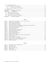
... Standards 49 Tables Table 1. Environmental Specifications 19 Table 5. Supported Memory Configurations 26 Table 10. Volatility Table 44 Table 16. Dimensions (mm) and Weight (kg 12 Front-Panel View 13 Back-Panel View 14 Internal-Chassis View 15 Power Button 15 LED Control Panel 16 PowerEdge T110 II Technical Guide v Electromagnetic Compatibility 48 B 4. Product Safety Certifications...
... Standards 49 Tables Table 1. Environmental Specifications 19 Table 5. Supported Memory Configurations 26 Table 10. Volatility Table 44 Table 16. Dimensions (mm) and Weight (kg 12 Front-Panel View 13 Back-Panel View 14 Internal-Chassis View 15 Power Button 15 LED Control Panel 16 PowerEdge T110 II Technical Guide v Electromagnetic Compatibility 48 B 4. Product Safety Certifications...

Technical Guide
Page 7
1.5 Business Friendly Easy to install, tailorable to your specific requirements and offering room for growth, the PowerEdge T110 II is the ideal server for small businesses and for remote offices of larger organizations. Get the processing power... Choose processor options and memory configurations that are balanced to run typical business applications, including Microsoft Windows Small Business Server, SQL Server® Workgroup/Standard, Active Directory®, SharePoint® Server and file and print. Meet the needs of PowerEdge T110 II to a design that gives you ...
1.5 Business Friendly Easy to install, tailorable to your specific requirements and offering room for growth, the PowerEdge T110 II is the ideal server for small businesses and for remote offices of larger organizations. Get the processing power... Choose processor options and memory configurations that are balanced to run typical business applications, including Microsoft Windows Small Business Server, SQL Server® Workgroup/Standard, Active Directory®, SharePoint® Server and file and print. Meet the needs of PowerEdge T110 II to a design that gives you ...

Technical Guide
Page 8
...ECC memory, add-in RAID, TPM/CTPM ECC memory, add-in RAID, TPM/CTPM Server Management Baseboard Management Controller (BMC), IPMI 2.0 compliant Baseboard Management Controller (BMC), IPMI 2.0 compliant Dell OpenManage™ Unified Server Configurator T310 ...or LCD diagnostic with hot-plug hard drive chassis Baseboard Management Controller (BMC), IPMI 2.0 compliant, Full Dell OpenManage™ suite Optional: iDRAC6 Express, iDRAC6 Enterprise, vFlash media I/O Slots NIC/LOM USB Power ...GOLD) Auto-ranging (100V~240V) Non-redundant, non-hot pluggable PowerEdge T110 II Technical Guide 8
...ECC memory, add-in RAID, TPM/CTPM ECC memory, add-in RAID, TPM/CTPM Server Management Baseboard Management Controller (BMC), IPMI 2.0 compliant Baseboard Management Controller (BMC), IPMI 2.0 compliant Dell OpenManage™ Unified Server Configurator T310 ...or LCD diagnostic with hot-plug hard drive chassis Baseboard Management Controller (BMC), IPMI 2.0 compliant, Full Dell OpenManage™ suite Optional: iDRAC6 Express, iDRAC6 Enterprise, vFlash media I/O Slots NIC/LOM USB Power ...GOLD) Auto-ranging (100V~240V) Non-redundant, non-hot pluggable PowerEdge T110 II Technical Guide 8

Technical Guide
Page 11
If not configured according to correct the configuration. actual capacity varies with 8MB memory Remote Management N/A Systems Management Dell™ OpenManage™ BMC, IPMI 2.0 compliant Unified Server Configurator Operating Systems Microsoft® Windows Server® 2012 Microsoft Windows Server ... the configuration is corrected. After a certain amount of time, the software will only run for one hour at http://go.microsoft.com/fwlink/?LinkId=143551 PowerEdge T110 II Technical Guide 11 Featured Database Applications Microsoft® SQL Server® solutions (see Dell.com/...
If not configured according to correct the configuration. actual capacity varies with 8MB memory Remote Management N/A Systems Management Dell™ OpenManage™ BMC, IPMI 2.0 compliant Unified Server Configurator Operating Systems Microsoft® Windows Server® 2012 Microsoft Windows Server ... the configuration is corrected. After a certain amount of time, the software will only run for one hour at http://go.microsoft.com/fwlink/?LinkId=143551 PowerEdge T110 II Technical Guide 11 Featured Database Applications Microsoft® SQL Server® solutions (see Dell.com/...

Technical Guide
Page 25
..., DDR3 UDIMM, 1333/1600 with ECC 8GB, DDR3 UDIMM, 1333/1600 with ECC 7.3 DIMM Slots The PowerEdge T110 II has four 72-bit (240-pin) DIMM slots for the T110 II are configured as 72 bits wide to 2 DIMMs per channel. For the latest information on memory options, visit Dell.com. The modules are listed in Table 9.
..., DDR3 UDIMM, 1333/1600 with ECC 8GB, DDR3 UDIMM, 1333/1600 with ECC 7.3 DIMM Slots The PowerEdge T110 II has four 72-bit (240-pin) DIMM slots for the T110 II are configured as 72 bits wide to 2 DIMMs per channel. For the latest information on memory options, visit Dell.com. The modules are listed in Table 9.


