
Installation and Troubleshooting Guide (.htm)
Page 8
...each system installed in the rack. Installation Instructions This installation guide provides instructions for another system may result in a rack. 6 Dell™ Rack Installation Guide The total rack load should not exceed 80 percent of American National Standards Institute (ANSI)/Electronic Industries ...pressing the component rail release latches and sliding a component into the rack. • Do not overload the AC power supply branch circuit that provides power to the rack. NOTICE: The RapidRails rack kit is intended to be installed in a rack that is installed in...
...each system installed in the rack. Installation Instructions This installation guide provides instructions for another system may result in a rack. 6 Dell™ Rack Installation Guide The total rack load should not exceed 80 percent of American National Standards Institute (ANSI)/Electronic Industries ...pressing the component rail release latches and sliding a component into the rack. • Do not overload the AC power supply branch circuit that provides power to the rack. NOTICE: The RapidRails rack kit is intended to be installed in a rack that is installed in...

Installation and Troubleshooting Guide (.htm)
Page 24
...5 system status indicator slot 5 2 strain-relief loops (1 per power supply, if available) 4 system status indicator 4 Attach the I/O cable connectors and power cable connectors to provide strain relief for the power cables. 22 Dell™ Rack Installation Guide NOTE: Use the strain-relief loops (...if available) on the back of the power supplies to their respective connectors on cable connections...
...5 system status indicator slot 5 2 strain-relief loops (1 per power supply, if available) 4 system status indicator 4 Attach the I/O cable connectors and power cable connectors to provide strain relief for the power cables. 22 Dell™ Rack Installation Guide NOTE: Use the strain-relief loops (...if available) on the back of the power supplies to their respective connectors on cable connections...
Information Update
Page 6
Safeguarding Encrypted Data 9 System Messages Update 9 Troubleshooting an SD+ Card or Internal USB Key 10 4 Contents External USB Diskette Drive Behavior During System Startup 8 Trusted Platform Module (TPM) Update 8 System Power Cable Requirements 8 System Board Replacement -
Safeguarding Encrypted Data 9 System Messages Update 9 Troubleshooting an SD+ Card or Internal USB Key 10 4 Contents External USB Diskette Drive Behavior During System Startup 8 Trusted Platform Module (TPM) Update 8 System Power Cable Requirements 8 System Board Replacement -
Information Update
Page 7
...-MHz memory modules will be added at this time. • On the CPU Information screen, the default setting for the Demand-Based Power Management option is Enabled. (This option is not available if AMD dual-core processors (Family 0Fh) are installed.) Information Update 5 System...this support will be available for download from support.dell.com. 8-GB Memory Modules 8-GB memory modules are not supported at a future date. Information Update This document provides updated information for your Hardware Owner's Manual: • The Low Power Mode option on the processor installed: •...
...-MHz memory modules will be added at this time. • On the CPU Information screen, the default setting for the Demand-Based Power Management option is Enabled. (This option is not available if AMD dual-core processors (Family 0Fh) are installed.) Information Update 5 System...this support will be available for download from support.dell.com. 8-GB Memory Modules 8-GB memory modules are not supported at a future date. Information Update This document provides updated information for your Hardware Owner's Manual: • The Low Power Mode option on the processor installed: •...
Information Update
Page 10
...PowerNow! feature is not available with TPM. feature is not displayed in China are not equipped with these processors, and the Demand-Based Power Management option is enabled. If this problem occurs, unplug and reinsert the drive cable to prompt the operating system to an incompatibility issue ... Opteron dual-core processors (Family 0Fh) and the system chipset, failures of your country. that meets or exceeds the voltage requirements of processor power transitions can occur if the AMD PowerNow! NOTICE: Do not use in the "Using the System Setup Program" chapter of less than 10A....
...PowerNow! feature is not available with TPM. feature is not displayed in China are not equipped with these processors, and the Demand-Based Power Management option is enabled. If this problem occurs, unplug and reinsert the drive cable to prompt the operating system to an incompatibility issue ... Opteron dual-core processors (Family 0Fh) and the system chipset, failures of your country. that meets or exceeds the voltage requirements of processor power transitions can occur if the AMD PowerNow! NOTICE: Do not use in the "Using the System Setup Program" chapter of less than 10A....
Information Update
Page 17
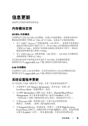
信息更新 800 MHz 800 MHz 667 MHz 或 533 MHz AMD™ Opteron 10h 800 MHz 667 MHz 533MHz AMD Opteron 0Fh 800 MHz 667 MHz 800 MHz support.dell.com BIOS。 8 GB 8 GB 8 GB support.dell.com BIOS。 Memory Information Low Power Mode • 在 CPU Information(CPU Demand-Based Power Management Enabled AMD 0Fh • 在 Processor X ID X ID • 在 Integrated Devices High Precision Event Timer (HPET HPET Enabled 信息更新 15
信息更新 800 MHz 800 MHz 667 MHz 或 533 MHz AMD™ Opteron 10h 800 MHz 667 MHz 533MHz AMD Opteron 0Fh 800 MHz 667 MHz 800 MHz support.dell.com BIOS。 8 GB 8 GB 8 GB support.dell.com BIOS。 Memory Information Low Power Mode • 在 CPU Information(CPU Demand-Based Power Management Enabled AMD 0Fh • 在 Processor X ID X ID • 在 Integrated Devices High Precision Event Timer (HPET HPET Enabled 信息更新 15
Information Update
Page 52
Memory Information Low Power Mode • CPU Information(CPU Demand-Based Power Management Enabled AMD 0Fh • Processor X ID 2 3 • Integrated Devices High Precision Event Timer (HPET Enabled 3-37 OS Windows Server 2003 SP1 6 GB Microsoft® Windows Server® 2003 SP1 USB http://support.microsoft.com/kb/923695 SP1 6 GB Windows Server 2003 SP2 50
Memory Information Low Power Mode • CPU Information(CPU Demand-Based Power Management Enabled AMD 0Fh • Processor X ID 2 3 • Integrated Devices High Precision Event Timer (HPET Enabled 3-37 OS Windows Server 2003 SP1 6 GB Microsoft® Windows Server® 2003 SP1 USB http://support.microsoft.com/kb/923695 SP1 6 GB Windows Server 2003 SP2 50
Information Update
Page 66
Opteron 0Fh)에서 AMD PowerNow Opteron 0Fh AMD PowerNow PowerNow Demand-Based Power Management System Setup 주 : PowerNow! 기능은 Opteron 10h USB 외장형 USB TPM (Trusted Platform Module TPM System Setup TPM 10A 10A 64
Opteron 0Fh)에서 AMD PowerNow Opteron 0Fh AMD PowerNow PowerNow Demand-Based Power Management System Setup 주 : PowerNow! 기능은 Opteron 10h USB 외장형 USB TPM (Trusted Platform Module TPM System Setup TPM 10A 10A 64
Getting Started Guide
Page 5
...An optional slim-line SATA DVD-ROM drive, slim-line SATA DVD-RW drive, or a combination CD-RW/DVD drive (when available). The power supplies support an input voltage range from 100 V to eight 2.5-inch hot-plug SAS hard drives. • An optional external USB diskette ...drive. • An optional external USB optical drive. • Two hot-pluggable, 1100W high efficiency power supplies in a 1 + 1 redundant configuration. Getting Started With Your System 3 System Features This section describes the major hardware and software features of...
...An optional slim-line SATA DVD-ROM drive, slim-line SATA DVD-RW drive, or a combination CD-RW/DVD drive (when available). The power supplies support an input voltage range from 100 V to eight 2.5-inch hot-plug SAS hard drives. • An optional external USB diskette ...drive. • An optional external USB optical drive. • Two hot-pluggable, 1100W high efficiency power supplies in a 1 + 1 redundant configuration. Getting Started With Your System 3 System Features This section describes the major hardware and software features of...
Getting Started Guide
Page 10
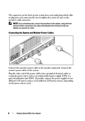
... at a time. The connectors on the power sources used. 8 Getting Started With Your System If possible, connect the power supplies to plug into a grounded electrical outlet or a separate power source such as an uninterrupted power supply (UPS) or a power distribution unit (PDU). Plug the other end...which cable to two different 110V power sources or two different 220V power sources, depending on the back of the power cables into each connector. Be sure to the monitor (optional). Connecting the System and Monitor Power Cables Connect the monitor's power cable to tighten the screws ...
... at a time. The connectors on the power sources used. 8 Getting Started With Your System If possible, connect the power supplies to plug into a grounded electrical outlet or a separate power source such as an uninterrupted power supply (UPS) or a power distribution unit (PDU). Plug the other end...which cable to two different 110V power sources or two different 220V power sources, depending on the back of the power cables into each connector. Be sure to the monitor (optional). Connecting the System and Monitor Power Cables Connect the monitor's power cable to tighten the screws ...
Getting Started Guide
Page 11
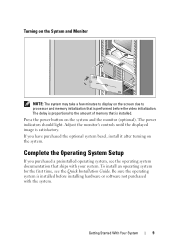
... memory initialization that ships with the system. If you purchased a preinstalled operating system, see the Quick Installation Guide. Getting Started With Your System 9 Press the power button on the system and the monitor (optional). To install an operating system for the first time, see the operating system documentation that is performed...
... memory initialization that ships with the system. If you purchased a preinstalled operating system, see the Quick Installation Guide. Getting Started With Your System 9 Press the power button on the system and the monitor (optional). To install an operating system for the first time, see the operating system documentation that is performed...
Getting Started Guide
Page 14
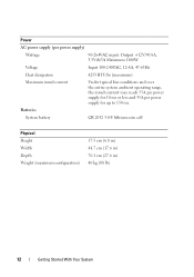
Power AC power supply (per power supply) Wattage 90-264VAC input: Output +12V/90.8A, 3.3Vsb/5A Maximum 1100W Voltage Input 100-240VAC, 12-8A, 47-63Hz Heat dissipation 4255 BTU/... inrush current Under typical line conditions and over the entire system ambient operating range, the inrush current may reach 55A per power supply for 10 ms or less and 35A per power supply for up to 150 ms. Batteries System battery CR 2032 3.0-V lithium coin cell Physical Height Width Depth Weight (maximum...
Power AC power supply (per power supply) Wattage 90-264VAC input: Output +12V/90.8A, 3.3Vsb/5A Maximum 1100W Voltage Input 100-240VAC, 12-8A, 47-63Hz Heat dissipation 4255 BTU/... inrush current Under typical line conditions and over the entire system ambient operating range, the inrush current may reach 55A per power supply for 10 ms or less and 35A per power supply for up to 150 ms. Batteries System battery CR 2032 3.0-V lithium coin cell Physical Height Width Depth Weight (maximum...
Hardware Owner's Manual (PDF)
Page 3
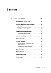
Contents 1 About Your System 11 Other Information You May Need 11 Accessing System Features During Startup 12 Front-Panel Features and Indicators 13 Hard-Drive Indicator Codes 16 Back-Panel Features and Indicators 17 Connecting External Devices 18 Power Indicator Codes 19 NIC Indicator Codes 20 LCD Status Messages 21 Solving Problems Described by LCD Status Messages 32 Removing LCD Status Messages 32 System Messages 33 Warning Messages 42 Diagnostics Messages 42 Alert Messages 42 Contents 3
Contents 1 About Your System 11 Other Information You May Need 11 Accessing System Features During Startup 12 Front-Panel Features and Indicators 13 Hard-Drive Indicator Codes 16 Back-Panel Features and Indicators 17 Connecting External Devices 18 Power Indicator Codes 19 NIC Indicator Codes 20 LCD Status Messages 21 Solving Problems Described by LCD Status Messages 32 Removing LCD Status Messages 32 System Messages 33 Warning Messages 42 Diagnostics Messages 42 Alert Messages 42 Contents 3
Hardware Owner's Manual (PDF)
Page 5
... Fan 67 Replacing a Cooling Fan 68 Cooling Shroud Assembly 69 Removing the Cooling Shroud Assembly 69 Replacing the Cooling Shroud Assembly. . . . . . 70 Power Supplies 71 Removing a Power Supply 71 Replacing a Power Supply 72 Processor Expansion Module 73 Removing the PEM or PEM Shell 73 Replacing the PEM or PEM Shell 76 Expansion Cards...
... Fan 67 Replacing a Cooling Fan 68 Cooling Shroud Assembly 69 Removing the Cooling Shroud Assembly 69 Replacing the Cooling Shroud Assembly. . . . . . 70 Power Supplies 71 Removing a Power Supply 71 Replacing a Power Supply 72 Processor Expansion Module 73 Removing the PEM or PEM Shell 73 Replacing the PEM or PEM Shell 76 Expansion Cards...
Hardware Owner's Manual (PDF)
Page 7
... a Fan Interposer Board 130 Installing a Fan Interposer Board 131 System Board (Service-Only Procedure 132 Removing the System Board 132 Installing the System Board 135 Power Distribution Board (Service-Only Procedure 137 Removing the...
... a Fan Interposer Board 130 Installing a Fan Interposer Board 131 System Board (Service-Only Procedure 132 Removing the System Board 132 Installing the System Board 135 Power Distribution Board (Service-Only Procedure 137 Removing the...
Hardware Owner's Manual (PDF)
Page 8
...Board 140 4 Troubleshooting Your System 143 Safety First-For You and Your System 143 Start-Up Routine 143 Checking Basic Power Problems 144 Checking the Equipment 144 Troubleshooting External Connections 144 Troubleshooting the Video Subsystem 145 Troubleshooting the Keyboard or Mouse....Troubleshooting a Wet System 152 Troubleshooting a Damaged System 152 Troubleshooting the System Battery 153 Troubleshooting Power Supplies 154 Troubleshooting System Cooling Problems 155 Troubleshooting a Fan 155 Troubleshooting System Memory 156 Troubleshooting an Optical Drive 158 8 Contents
...Board 140 4 Troubleshooting Your System 143 Safety First-For You and Your System 143 Start-Up Routine 143 Checking Basic Power Problems 144 Checking the Equipment 144 Troubleshooting External Connections 144 Troubleshooting the Video Subsystem 145 Troubleshooting the Keyboard or Mouse....Troubleshooting a Wet System 152 Troubleshooting a Damaged System 152 Troubleshooting the System Battery 153 Troubleshooting Power Supplies 154 Troubleshooting System Cooling Problems 155 Troubleshooting a Fan 155 Troubleshooting System Memory 156 Troubleshooting an Optical Drive 158 8 Contents
Hardware Owner's Manual (PDF)
Page 14
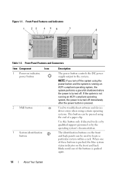
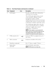
.... If the system is not running an ACPI-compliant operating system, the system performs a graceful shutdown before the power is turned off immediately after the power button is pushed again. 14 About Your System Use this button only if directed to the system. Front-Panel... Features and Connectors Item Component Icon 1 Power-on indicator, power button 2 NMI button 3 System identification button Description The power button controls the DC power supply output to do so by qualified support personnel or by the operating system's documentation....
.... If the system is not running an ACPI-compliant operating system, the system performs a graceful shutdown before the power is turned off immediately after the power button is pushed again. 14 About Your System Use this button only if directed to the system. Front-Panel... Features and Connectors Item Component Icon 1 Power-on indicator, power button 2 NMI button 3 System identification button Description The power button controls the DC power supply output to do so by qualified support personnel or by the operating system's documentation....
Hardware Owner's Manual (PDF)
Page 15
... an error has been detected, the LCD display lights amber regardless of the system can cause the LCD to flash blue to a problem with power supplies, fans, system temperature, or hard drives. The LCD display lights during normal system operation. Table 1-2. NOTE: If the system is connected to the system. 7 ... devices are data only. Both the systems management software and the identification buttons located on the front and back of whether the system has been powered on.
... an error has been detected, the LCD display lights amber regardless of the system can cause the LCD to flash blue to a problem with power supplies, fans, system temperature, or hard drives. The LCD display lights during normal system operation. Table 1-2. NOTE: If the system is connected to the system. 7 ... devices are data only. Both the systems management software and the identification buttons located on the front and back of whether the system has been powered on.
Hardware Owner's Manual (PDF)
Page 17
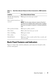
... Blinks green three seconds, amber three seconds, and off . Hard-Drive Indicator Patterns for insertion or removal during this time. Drives are initialized after system power is applied. Drive online Steady green. Back-Panel Features and Indicators Figure 1-3 shows the controls, indicators, and connectors located on the system's back panel. About...
... Blinks green three seconds, amber three seconds, and off . Hard-Drive Indicator Patterns for insertion or removal during this time. Drives are initialized after system power is applied. Drive online Steady green. Back-Panel Features and Indicators Figure 1-3 shows the controls, indicators, and connectors located on the system's back panel. About...
Hardware Owner's Manual (PDF)
Page 18
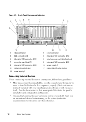
...video connector 3 USB connectors (2) 5 integrated NIC connector NIC1 7 expansion-card slots (7) 9 integrated NIC connector NIC4 11 system status indicator 13 power supply 1 12 11 10 2 serial connector 4 integrated NIC connector NIC2 6 remote access controller (optional) 8 integrated NIC connector NIC3 10... power supply 2 12 system identification button Connecting External Devices When connecting external devices to your system, follow these guidelines: &#...
...video connector 3 USB connectors (2) 5 integrated NIC connector NIC1 7 expansion-card slots (7) 9 integrated NIC connector NIC4 11 system status indicator 13 power supply 1 12 11 10 2 serial connector 4 integrated NIC connector NIC2 6 remote access controller (optional) 8 integrated NIC connector NIC3 10... power supply 2 12 system identification button Connecting External Devices When connecting external devices to your system, follow these guidelines: &#...


