Information Update
Page 7
... installed.) Information Update 5 Support for the Demand-Based Power Management option is Enabled. (This option is not available if AMD dual-core processors (Family 0Fh) are installed per processor will be added at a future date. Memory Module Support 800-MHz Memory Modules 800-MHz memory modules are not supported at this time. • On the CPU Information screen, the default setting for configurations of up to four 800-MHz memory modules per processor, the memory modules...
... installed.) Information Update 5 Support for the Demand-Based Power Management option is Enabled. (This option is not available if AMD dual-core processors (Family 0Fh) are installed per processor will be added at a future date. Memory Module Support 800-MHz Memory Modules 800-MHz memory modules are not supported at this time. • On the CPU Information screen, the default setting for configurations of up to four 800-MHz memory modules per processor, the memory modules...
Information Update
Page 11
... LAN-onmotherboard (LOM) card was detected in the dedicated LOM mezzanine card slot. TPM configuration This message displays during system setup. Ensure that the configuration change which may reset the system. Safeguarding Encrypted Data If your system before you are new. If you replace the system board, you must supply the recovery key when you restart your system is required (M) to Modify to to support the TPM feature, you can use...
... LAN-onmotherboard (LOM) card was detected in the dedicated LOM mezzanine card slot. TPM configuration This message displays during system setup. Ensure that the configuration change which may reset the system. Safeguarding Encrypted Data If your system before you are new. If you replace the system board, you must supply the recovery key when you restart your system is required (M) to Modify to to support the TPM feature, you can use...
Getting Started Guide
Page 5
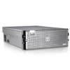
...; The baseboard has CPU 1 and CPU 2 sockets with 16 DIMM slots. • CPU 3 and CPU 4 and their 16 DIMM slots are on the system board and Processor Expansion Module (PEM). • 800-MHZ DDR2 memory modules are supported in restricted configurations. • An optional slim-line SATA DVD-ROM drive, slim-line SATA DVD-RW drive, or a combination CD-RW/DVD drive (when available). Getting Started With Your System 3 The power supplies support an input voltage range from 100 V to...
...; The baseboard has CPU 1 and CPU 2 sockets with 16 DIMM slots. • CPU 3 and CPU 4 and their 16 DIMM slots are on the system board and Processor Expansion Module (PEM). • 800-MHZ DDR2 memory modules are supported in restricted configurations. • An optional slim-line SATA DVD-ROM drive, slim-line SATA DVD-RW drive, or a combination CD-RW/DVD drive (when available). Getting Started With Your System 3 The power supplies support an input voltage range from 100 V to...
Getting Started Guide
Page 6
... a daughter card that can be upgraded to 10Gb Ethernet. • An integrated Trusted Platform Module (TPM) version 1.2 used instead.) • Front-panel support for a video connector, two USB connectors, and a 1x5 LCD panel for system ID and error messaging. • Back-panel connectors including one serial, one video, two USB, and four NIC connectors. • System ID button on page 10. 4 Getting Started With Your System For more information about specific features, see "Technical Specifications" on...
... a daughter card that can be upgraded to 10Gb Ethernet. • An integrated Trusted Platform Module (TPM) version 1.2 used instead.) • Front-panel support for a video connector, two USB connectors, and a 1x5 LCD panel for system ID and error messaging. • Back-panel connectors including one serial, one video, two USB, and four NIC connectors. • System ID button on page 10. 4 Getting Started With Your System For more information about specific features, see "Technical Specifications" on...
Hardware Owner's Manual (PDF)
Page 38
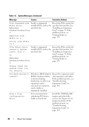
..." on page 164. 38 About Your System PCI BIOS failed to an "Troubleshooting expansion card is faulty or improperly installed. an expansion page 164. If the n problem persists, see Expected Link Width is detected during If the problem persists, see "Troubleshooting Expansion Cards" on page 179. See reset: Slot n specified slot. is n "Getting Help" on unseated; A cable to install PCI device BIOS (Option Reseat the expansion cards ROM) checksum failure and expansion card cables. See Figure 6-1 for details. If the...
..." on page 164. 38 About Your System PCI BIOS failed to an "Troubleshooting expansion card is faulty or improperly installed. an expansion page 164. If the n problem persists, see Expected Link Width is detected during If the problem persists, see "Troubleshooting Expansion Cards" on page 179. See reset: Slot n specified slot. is n "Getting Help" on unseated; A cable to install PCI device BIOS (Option Reseat the expansion cards ROM) checksum failure and expansion card cables. See Figure 6-1 for details. If the...
Hardware Owner's Manual (PDF)
Page 41
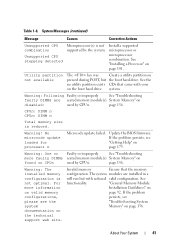
... the memory configuration. page 156. CPUn: DIMM n CPUn: DIMM n Total memory size is not optimal. No microcode update loaded for processor n Microcode update failed. For more faulty DIMMs seated memory module(s) System Memory" on found on the boot hard drive. Install a supported microprocessor or microprocessor combination. See "Installing a Processor" on page 92. Utility partition not available The key was Create a utility partition on pressed during POST, but with your on CPUn used by CPUn. Warning: Following...
... the memory configuration. page 156. CPUn: DIMM n CPUn: DIMM n Total memory size is not optimal. No microcode update loaded for processor n Microcode update failed. For more faulty DIMMs seated memory module(s) System Memory" on found on the boot hard drive. Install a supported microprocessor or microprocessor combination. See "Installing a Processor" on page 92. Utility partition not available The key was Create a utility partition on pressed during POST, but with your on CPUn used by CPUn. Warning: Following...
Hardware Owner's Manual (PDF)
Page 46
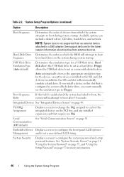
..., "Using the System Password" on page 55, and "Using the Setup Password" on the PCI bus, and any installed expansion card that is not supported from external devices. NOTE: System boot is configured as a removable diskette drive, you must manually set a user-defined LCD string. Integrated Devices See "Integrated Devices Screen" on page 51. Hard-Disk Drive Determines the order in this field is enabled and the system has failed to boot, the system will automatically emulate a hard drive...
..., "Using the System Password" on page 55, and "Using the Setup Password" on the PCI bus, and any installed expansion card that is not supported from external devices. NOTE: System boot is configured as a removable diskette drive, you must manually set a user-defined LCD string. Integrated Devices See "Integrated Devices Screen" on page 51. Hard-Disk Drive Determines the order in this field is enabled and the system has failed to boot, the system will automatically emulate a hard drive...
Hardware Owner's Manual (PDF)
Page 48
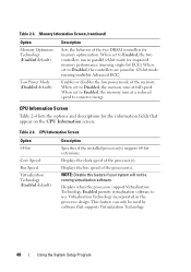
... System Setup Program Displays when the processors support Virtualization Technology. This feature can only be running multi-bit Advanced ECC. When set to Disabled, the controllers are joined in the processor design. Enables or disables the low power mode of the processor(s). CPU Information Screen Option 64-bit Core Speed Bus Speed Virtualization Technology (Enabled default) Description Specifies if the installed processor(s) support 64-bit extensions. Table 2-4. Enabled permits virtualization software to conserve energy. When set to Enabled, the memory runs at...
... System Setup Program Displays when the processors support Virtualization Technology. This feature can only be running multi-bit Advanced ECC. When set to Disabled, the controllers are joined in the processor design. Enables or disables the low power mode of the processor(s). CPU Information Screen Option 64-bit Core Speed Bus Speed Virtualization Technology (Enabled default) Description Specifies if the installed processor(s) support 64-bit extensions. Table 2-4. Enabled permits virtualization software to conserve energy. When set to Enabled, the memory runs at...
Hardware Owner's Manual (PDF)
Page 50
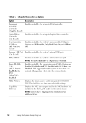
... Detected Displays the NIC features provided by the NIC hardware key installed in the TOE_KEY socket on the system board. User Accessible USB Ports (All Ports On default) Enables or disables the system's user accessible USB ports. PXE support allows the system to a hypervisor, if installed. MAC Address Displays the MAC address for the integrated 10/100/1000 NIC. NOTE: Some features may require the installation of an additional driver. 50 Using the System Setup Program Internal USB Port Enables or disables the system's internal USB port. (On default) SD Card Port Enables...
... Detected Displays the NIC features provided by the NIC hardware key installed in the TOE_KEY socket on the system board. User Accessible USB Ports (All Ports On default) Enables or disables the system's user accessible USB ports. PXE support allows the system to a hypervisor, if installed. MAC Address Displays the MAC address for the integrated 10/100/1000 NIC. NOTE: Some features may require the installation of an additional driver. 50 Using the System Setup Program Internal USB Port Enables or disables the system's internal USB port. (On default) SD Card Port Enables...
Hardware Owner's Manual (PDF)
Page 54
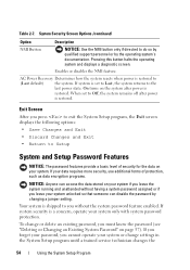
...'s documentation. Enables or disables the NMI feature. When set to Setup System and Setup Password Features NOTICE: The password features provide a basic level of protection, such as data encryption programs. NOTICE: Anyone can access the data stored on the system after power is set to Last, the system returns to do so by qualified support personnel or by changing a jumper setting. To change settings in the System Setup program until a trained service...
...'s documentation. Enables or disables the NMI feature. When set to Setup System and Setup Password Features NOTICE: The password features provide a basic level of protection, such as data encryption programs. NOTICE: Anyone can access the data stored on the system after power is set to Last, the system returns to do so by qualified support personnel or by changing a jumper setting. To change settings in the System Setup program until a trained service...

Hardware Owner's Manual (PDF)
Page 55
... existing passwords. Using the System Password After a system password is not assigned and the password jumper on page 171. This procedure is described in "Disabling a Forgotten Password" on the system board is in the enabled (default) position, the setting shown for the System Password option is Unlocked, you cannot change the system password. If the setting shown for the Password Status is Enabled. However, certain key combinations are not valid. password jumper setting...
... existing passwords. Using the System Password After a system password is not assigned and the password jumper on page 171. This procedure is described in "Disabling a Forgotten Password" on the system board is in the enabled (default) position, the setting shown for the System Password option is Unlocked, you cannot change the system password. If the setting shown for the Password Status is Enabled. However, certain key combinations are not valid. password jumper setting...

Hardware Owner's Manual (PDF)
Page 107
... "Using the System Setup Program" on page 43 for these drives are normal. Installing a Drive Blank The drive blank is free. When you format a high-capacity hard drive, allow enough time for the formatting to be attached to the primary (or boot) controller. Removing a Drive Blank NOTICE: To maintain proper system cooling, all empty hard-drive bays must replace the carrier with a drive blank. 1 Remove the bezel. Configuring...
... "Using the System Setup Program" on page 43 for these drives are normal. Installing a Drive Blank The drive blank is free. When you format a high-capacity hard drive, allow enough time for the formatting to be attached to the primary (or boot) controller. Removing a Drive Blank NOTICE: To maintain proper system cooling, all empty hard-drive bays must replace the carrier with a drive blank. 1 Remove the bezel. Configuring...

Hardware Owner's Manual (PDF)
Page 115
... safety precautions, working inside the computer, and protecting against electrostatic discharge. See "Installing an Expansion Card" on page 78. 5 Connect the end of the Fibre Channel cable to the connector on . See "Opening the System" on page 65. 3 Remove the PEM. CAUTION: Only trained service technicians are authorized to remove the system cover and access any of the components inside the system.
... safety precautions, working inside the computer, and protecting against electrostatic discharge. See "Installing an Expansion Card" on page 78. 5 Connect the end of the Fibre Channel cable to the connector on . See "Opening the System" on page 65. 3 Remove the PEM. CAUTION: Only trained service technicians are authorized to remove the system cover and access any of the components inside the system.
Hardware Owner's Manual (PDF)
Page 149
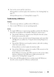
... another USB connector on the system, and turn on page 43. 4 Turn on page 179. d Turn off the USB device, disconnect the USB cable from the system except the USB mouse and keyboard. a Turn off the USB device, connect it to step 2. Troubleshooting Your System 149 If the problem persists, see "Getting Help" on the system and the serial device. If the problem is resolved, replace the interface cable. See "Using the System Setup...
... another USB connector on the system, and turn on page 43. 4 Turn on page 179. d Turn off the USB device, disconnect the USB cable from the system except the USB mouse and keyboard. a Turn off the USB device, connect it to step 2. Troubleshooting Your System 149 If the problem persists, see "Getting Help" on the system and the serial device. If the problem is resolved, replace the interface cable. See "Using the System Setup...
Hardware Owner's Manual (PDF)
Page 151
... switches on the NIC connector. See Network Cable Requirements in your Getting Started Guide. Remove and reinstall the drivers if applicable. See "Using the System Setup Program" on page 43. 5 Ensure that the appropriate drivers are installed and the protocols are enabled. Troubleshooting a NIC Problem • NIC cannot communicate with network. See the NIC documentation. 4 Enter the System Setup program and confirm that all network cables are all cable connections. • If the activity indicator does not light...
... switches on the NIC connector. See Network Cable Requirements in your Getting Started Guide. Remove and reinstall the drivers if applicable. See "Using the System Setup Program" on page 43. 5 Ensure that the appropriate drivers are installed and the protocols are enabled. Troubleshooting a NIC Problem • NIC cannot communicate with network. See the NIC documentation. 4 Enter the System Setup program and confirm that all network cables are all cable connections. • If the activity indicator does not light...
Hardware Owner's Manual (PDF)
Page 155
...; Cables inside the system obstruct airflow. • An individual cooling fan is removed or has failed. NOTE: After installing a new power supply, allow several seconds for the system to recognize the power supply and to signify that the power supply is working properly. Troubleshooting a Fan Problem • System-status indicator is properly installed by removing and reinstalling it is functioning properly. Troubleshooting System Cooling Problems Problem • Systems management software issues a fan-related error message...
...; Cables inside the system obstruct airflow. • An individual cooling fan is removed or has failed. NOTE: After installing a new power supply, allow several seconds for the system to recognize the power supply and to signify that the power supply is working properly. Troubleshooting a Fan Problem • System-status indicator is properly installed by removing and reinstalling it is functioning properly. Troubleshooting System Cooling Problems Problem • Systems management software issues a fan-related error message...
Hardware Owner's Manual (PDF)
Page 167
... problem. Dell PowerEdge Diagnostics is a suite of tests. • Repeat tests. • Display, print, or save test results. • Temporarily suspend testing if an error is detected or terminate testing when a user-defined error limit is to test your system, run PowerEdge Diagnostics for systems running supported Microsoft® Windows® and Linux operating systems are available at support.dell.com and on chassis and storage components such as hard drives, physical memory, communications and printer ports, NICs, CMOS, and more. The system diagnostics...
... problem. Dell PowerEdge Diagnostics is a suite of tests. • Repeat tests. • Display, print, or save test results. • Temporarily suspend testing if an error is detected or terminate testing when a user-defined error limit is to test your system, run PowerEdge Diagnostics for systems running supported Microsoft® Windows® and Linux operating systems are available at support.dell.com and on chassis and storage components such as hard drives, physical memory, communications and printer ports, NICs, CMOS, and more. The system diagnostics...
Hardware Owner's Manual (PDF)
Page 181
... important start-up your system. backup battery - Your system's BIOS contains programs stored on a regular basis. A module that maintains system configuration, date, and time information in the U.S. Baseboard management controller. ANSI - beep code - For example, one beep, followed by your system's hard drive on a flash memory chip. BMC - ACPI - A battery that contains a processor, memory, and a hard drive. The modules are mounted into a chassis that includes power supplies and fans. ASCII - An individual code assigned to the configuration of memory...
... important start-up your system. backup battery - Your system's BIOS contains programs stored on a regular basis. A module that maintains system configuration, date, and time information in the U.S. Baseboard management controller. ANSI - beep code - For example, one beep, followed by your system's hard drive on a flash memory chip. BMC - ACPI - A battery that contains a processor, memory, and a hard drive. The modules are mounted into a chassis that includes power supplies and fans. ASCII - An individual code assigned to the configuration of memory...
Hardware Owner's Manual (PDF)
Page 190
... password protection. USB devices can be terminated to manage system resources-memory, disk drives, or printers, for the Windows operating environment. See bootable diskette. system memory - TCP/IP - TCP/IP offload engine. Uninterruptible power supply. Volt(s). Volt(s) alternating current. UPS - USB - Universal Serial Bus. Volt(s) direct current. A start Windows, it consults the system.ini file to enable or disable the termination on these devices by changing jumper or switch settings on a network hub or switch used to connect...
... password protection. USB devices can be terminated to manage system resources-memory, disk drives, or printers, for the Windows operating environment. See bootable diskette. system memory - TCP/IP - TCP/IP offload engine. Uninterruptible power supply. Volt(s). Volt(s) alternating current. UPS - USB - Universal Serial Bus. Volt(s) direct current. A start Windows, it consults the system.ini file to enable or disable the termination on these devices by changing jumper or switch settings on a network hub or switch used to connect...
Hardware Owner's Manual (PDF)
Page 196
... P passwords disabling, 171 setup, 57 system, 55 PEM connectors, 175 removing, 73 replacing, 76 phone numbers, 179 POST keystrokes, 12 power distribution board installing, 138 removing, 137 power indicator, 19 power supplies removing, 71 replacing, 72 troubleshooting, 154 PowerNow!, 49 processor installing, 101 replacing, 99 troubleshooting, 165 processor expansion module See PEM. removing bezel, 64 chassis intrusion switch, 120 control panel assembly, 118 cooling fan, 67 cooling shroud, 69 cover, 65 expansion card, 80 fan interposer board, 130 hard drive blank, 107 hard drives, 108 memory...
... P passwords disabling, 171 setup, 57 system, 55 PEM connectors, 175 removing, 73 replacing, 76 phone numbers, 179 POST keystrokes, 12 power distribution board installing, 138 removing, 137 power indicator, 19 power supplies removing, 71 replacing, 72 troubleshooting, 154 PowerNow!, 49 processor installing, 101 replacing, 99 troubleshooting, 165 processor expansion module See PEM. removing bezel, 64 chassis intrusion switch, 120 control panel assembly, 118 cooling fan, 67 cooling shroud, 69 cover, 65 expansion card, 80 fan interposer board, 130 hard drive blank, 107 hard drives, 108 memory...

