Information Update
Page 7
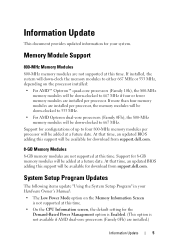
... the CPU Information screen, the default setting for download from support.dell.com. Information Update This document provides updated information for configurations of up to four 800-MHz memory modules per processor. If more than four memory modules are installed per processor, the memory modules will be down-clocked to 533 MHz. • For AMD...
... the CPU Information screen, the default setting for download from support.dell.com. Information Update This document provides updated information for configurations of up to four 800-MHz memory modules per processor. If more than four memory modules are installed per processor, the memory modules will be down-clocked to 533 MHz. • For AMD...
Information Update
Page 9
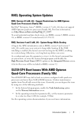
Support Restrictions for example, 3900m). As a workaround, pass the parameter nohpet to load on systems configured with quad-core processors and more than 4-GB (for AMD Opteron Quad-Core Processors (Family 10h) Red Hat® Enterprise Linux® (RHEL) version 4.5... more information, see http://kbase.redhat.com/faq/FAQ_85_11697. See the operating system documentation if you can bypass the issue by using one of RAM memory. RHEL Operating System Updates RHEL Version 4.5 (x86_64) - System Hangs While Booting A bug in the APIC initialization code in a system hang. A future maintenance ...
Support Restrictions for example, 3900m). As a workaround, pass the parameter nohpet to load on systems configured with quad-core processors and more than 4-GB (for AMD Opteron Quad-Core Processors (Family 10h) Red Hat® Enterprise Linux® (RHEL) version 4.5... more information, see http://kbase.redhat.com/faq/FAQ_85_11697. See the operating system documentation if you can bypass the issue by using one of RAM memory. RHEL Operating System Updates RHEL Version 4.5 (x86_64) - System Hangs While Booting A bug in the APIC initialization code in a system hang. A future maintenance ...
Getting Started Guide
Page 5
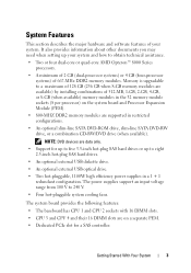
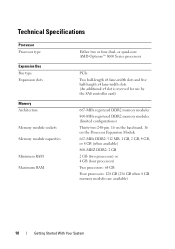
...has CPU 1 and CPU 2 sockets with 16 DIMM slots. • CPU 3 and CPU 4 and their 16 DIMM slots are supported in restricted configurations. • An optional slim-line SATA DVD-ROM drive, slim-line SATA DVD-RW drive, or a combination CD-RW/DVD drive (when available... hot-pluggable, 1100W high efficiency power supplies in a 1 + 1 redundant configuration. Memory is upgradable to a maximum of 128 GB (256 GB when 8-GB memory modules are available) by installing combinations of 667-MHz DDR2 memory modules. System Features This section describes the major hardware and software features of your...
...has CPU 1 and CPU 2 sockets with 16 DIMM slots. • CPU 3 and CPU 4 and their 16 DIMM slots are supported in restricted configurations. • An optional slim-line SATA DVD-ROM drive, slim-line SATA DVD-RW drive, or a combination CD-RW/DVD drive (when available... hot-pluggable, 1100W high efficiency power supplies in a 1 + 1 redundant configuration. Memory is upgradable to a maximum of 128 GB (256 GB when 8-GB memory modules are available) by installing combinations of 667-MHz DDR2 memory modules. System Features This section describes the major hardware and software features of your...
Getting Started Guide
Page 12
...-length x4 lane-width slots (An additional x4 slot is reserved for use by the SAS controller card) 667-MHz registered DDR2 memory modules 800-MHz registered DDR2 memory modules (limited configurations) Thirty-two 240-pin. 16 on the baseboard, 16 on the Processor Expansion Module 667-MHz DDR2: 512 MB, 1 GB, 2 GB...
...-length x4 lane-width slots (An additional x4 slot is reserved for use by the SAS controller card) 667-MHz registered DDR2 memory modules 800-MHz registered DDR2 memory modules (limited configurations) Thirty-two 240-pin. 16 on the baseboard, 16 on the Processor Expansion Module 667-MHz DDR2: 512 MB, 1 GB, 2 GB...
Hardware Owner's Manual (PDF)
Page 4
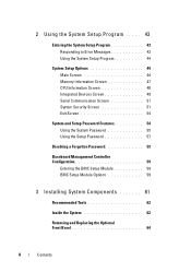
...the System Setup Program 43 Responding to Error Messages 43 Using the System Setup Program 44 System Setup Options 44 Main Screen 44 Memory Information Screen 47 CPU Information Screen 48 Integrated Devices Screen 49 Serial Communication Screen 51 System Security Screen 51 Exit Screen 54 System... Password Features 54 Using the System Password 55 Using the Setup Password 57 Disabling a Forgotten Password 59 Baseboard Management Controller Configuration 59 Entering the BMC Setup Module 59 BMC Setup Module Options 59 3 Installing System Components 61 Recommended Tools 62 Inside ...
...the System Setup Program 43 Responding to Error Messages 43 Using the System Setup Program 44 System Setup Options 44 Main Screen 44 Memory Information Screen 47 CPU Information Screen 48 Integrated Devices Screen 49 Serial Communication Screen 51 System Security Screen 51 Exit Screen 54 System... Password Features 54 Using the System Password 55 Using the Setup Password 57 Disabling a Forgotten Password 59 Baseboard Management Controller Configuration 59 Entering the BMC Setup Module 59 BMC Setup Module Options 59 3 Installing System Components 61 Recommended Tools 62 Inside ...
Hardware Owner's Manual (PDF)
Page 6
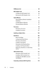
... Card 89 Removing the NIC Daughter Card 91 System Memory 91 General Memory Module Installation Guidelines 92 Installing Memory Modules 95 Removing Memory Modules 97 Processors 98 Removing a Processor 99 Installing a Processor 101 Installing an Optical Drive 103 Hard Drives 105 Before You Begin 106 Configuring the Boot Device 107 Removing a Drive Blank 107 Installing...
... Card 89 Removing the NIC Daughter Card 91 System Memory 91 General Memory Module Installation Guidelines 92 Installing Memory Modules 95 Removing Memory Modules 97 Processors 98 Removing a Processor 99 Installing a Processor 101 Installing an Optical Drive 103 Hard Drives 105 Before You Begin 106 Configuring the Boot Device 107 Removing a Drive Blank 107 Installing...
Hardware Owner's Manual (PDF)
Page 28
... Board Connectors" on page 156. Memory detected, but not usable. Information only. See or unseated. SAS cable B is not configurable. Error detected during memory configuration. Check the memory configuration and reinstall the memory modules if necessary. See "Troubleshooting System Memory" on page 176. Memory is configured, See "Troubleshooting but is unseated, missing, or bad. Memory System Memory" on subsystem failure. page 156...
... Board Connectors" on page 156. Memory detected, but not usable. Information only. See or unseated. SAS cable B is not configurable. Error detected during memory configuration. Check the memory configuration and reinstall the memory modules if necessary. See "Troubleshooting System Memory" on page 176. Memory is configured, See "Troubleshooting but is unseated, missing, or bad. Memory System Memory" on subsystem failure. page 156...

Hardware Owner's Manual (PDF)
Page 30
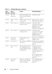
... until the system is rebooted. LCD Status Messages (continued) Line 1 Line 2 Message Message Causes Corrective Actions E201F DRAC Config Remote access controller (RAC) configuration failure. E2021 Memory Population Incorrect memory configuration. E2022 POST Fail General failure after video. Check screen for specific error messages. See "RAC Card" on bit error (SBE) logging, page 156...
... until the system is rebooted. LCD Status Messages (continued) Line 1 Line 2 Message Message Causes Corrective Actions E201F DRAC Config Remote access controller (RAC) configuration failure. E2021 Memory Population Incorrect memory configuration. E2022 POST Fail General failure after video. Check screen for specific error messages. See "RAC Card" on bit error (SBE) logging, page 156...

Hardware Owner's Manual (PDF)
Page 33
...when the message appears or the operating system's documentation for the application that is recorded from another source that the memory Interleaving configuration does not modules are authorized to remove the system cover and access any of the components inside the computer, and... electrostatic discharge. See your Product Information Guide for each message. The system node interleaving. About Your System 33 Memory support node configuration that can occur and the probable cause and corrective action for complete information about safety precautions, working inside the ...
...when the message appears or the operating system's documentation for the application that is recorded from another source that the memory Interleaving configuration does not modules are authorized to remove the system cover and access any of the components inside the computer, and... electrostatic discharge. See your Product Information Guide for each message. The system node interleaving. About Your System 33 Memory support node configuration that can occur and the probable cause and corrective action for complete information about safety precautions, working inside the ...

Hardware Owner's Manual (PDF)
Page 34
... properly installed. Please wait... Remote BIOS update attempt failed. Caution! Decreasing available memory Faulty or improperly installed memory modules. MANUFACTURING MODE will be cleared before the next boot. system board. See... Figure 6-1 for normal operation. Microprocessors with different cache sizes detected! System reboot required for jumper locations. NVRAM_CLR NVRAM_CLR jumper is jumper is being processed. Retry the BIOS update. Remote Configuration...
... properly installed. Please wait... Remote BIOS update attempt failed. Caution! Decreasing available memory Faulty or improperly installed memory modules. MANUFACTURING MODE will be cleared before the next boot. system board. See... Figure 6-1 for normal operation. Microprocessors with different cache sizes detected! System reboot required for jumper locations. NVRAM_CLR NVRAM_CLR jumper is jumper is being processed. Retry the BIOS update. Remote Configuration...

Hardware Owner's Manual (PDF)
Page 35
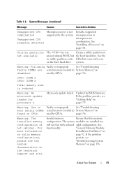
... command. See the applicable troubleshooting section in the SEL. If the problem persists, see "Troubleshooting System Memory" on page 92 for memory configuration information. About Your System 35 board. System Messages (continued) Message Causes Corrective Actions Error: Incorrect memory configuration CPU n The DIMM group for any faulty components specified in "Troubleshooting Your System" on page...
... command. See the applicable troubleshooting section in the SEL. If the problem persists, see "Troubleshooting System Memory" on page 92 for memory configuration information. About Your System 35 board. System Messages (continued) Message Causes Corrective Actions Error: Incorrect memory configuration CPU n The DIMM group for any faulty components specified in "Troubleshooting Your System" on page...

Hardware Owner's Manual (PDF)
Page 36
...) Message Causes Corrective Actions Invalid NVRAM configuration, Resource Reallocated System detected and corrected a resource conflict. No action is installed SAS controller in the in detected manufacturing mode. controller slot. See "Troubleshooting System Memory" on Controller failure controller; board Manufacturing...keyboard See "Getting Help" on page 156. Memory double word logic failure at address, read value expecting value Memory odd/even logic failure at address, read value expecting value Memory write/read failure at address, read value expecting ...
...) Message Causes Corrective Actions Invalid NVRAM configuration, Resource Reallocated System detected and corrected a resource conflict. No action is installed SAS controller in the in detected manufacturing mode. controller slot. See "Troubleshooting System Memory" on Controller failure controller; board Manufacturing...keyboard See "Getting Help" on page 156. Memory double word logic failure at address, read value expecting value Memory odd/even logic failure at address, read value expecting value Memory write/read failure at address, read value expecting ...

Hardware Owner's Manual (PDF)
Page 37
...no boot disk in System Setup program, or no operating system on hard drive Incorrect configuration settings in drive A. See your hard drive. System Messages (continued) Message Causes Corrective Actions Memory tests terminated by pressing the spacebar. Use a bootable diskette, CD, or hard drive...If necessary, install the operating system on page 158. Check the hard-drive configuration settings in the System Setup program. See "Using the System Setup Program" on page 179. POST memory test terminated by keystroke. Information only. See "Getting Help" on page 43...
...no boot disk in System Setup program, or no operating system on hard drive Incorrect configuration settings in drive A. See your hard drive. System Messages (continued) Message Causes Corrective Actions Memory tests terminated by pressing the spacebar. Use a bootable diskette, CD, or hard drive...If necessary, install the operating system on page 158. Check the hard-drive configuration settings in the System Setup program. See "Using the System Setup Program" on page 179. POST memory test terminated by keystroke. Information only. See "Getting Help" on page 43...
Hardware Owner's Manual (PDF)
Page 41
... POST, but with your on disabled: used by CPUn. Warning: One or Faulty or improperly See "Troubleshooting more information on valid memory configurations, please see "Getting Help" on page 156. "General Memory Module Installation Guidelines" on page 101. Warning! Update the BIOS firmware. page 156. system. If the problem persists, see "Troubleshooting System...
... POST, but with your on disabled: used by CPUn. Warning: One or Faulty or improperly See "Troubleshooting more information on valid memory configurations, please see "Getting Help" on page 156. "General Memory Module Installation Guidelines" on page 101. Warning! Update the BIOS firmware. page 156. system. If the problem persists, see "Troubleshooting System...

Hardware Owner's Manual (PDF)
Page 43
NOTE: To ensure an orderly system shutdown, see the documentation that accompanied your system. NOTE: After installing a memory upgrade, it is booting, make a note of the message and suggestions for future reference. Before entering the System Setup program, see the following ...F2 = System Setup If your operating system begins to load before you press , allow the system to finish booting, and then restart your system configuration and optional settings. Using the System Setup Program 43 Responding to Error Messages You can use the System Setup program to: • Change the...
NOTE: To ensure an orderly system shutdown, see the documentation that accompanied your system. NOTE: After installing a memory upgrade, it is booting, make a note of the message and suggestions for future reference. Before entering the System Setup program, see the following ...F2 = System Setup If your operating system begins to load before you press , allow the system to finish booting, and then restart your system configuration and optional settings. Using the System Setup Program 43 Responding to Error Messages You can use the System Setup program to: • Change the...

Hardware Owner's Manual (PDF)
Page 47
... relating to Disabled, the system can support NonUniform Memory architecture (NUMA) (asymmetric) memory configurations. Memory Information Screen Table 2-4 lists the descriptions for host systems that appear on 101- Memory Information Screen Option Description System Memory Size Displays the amount of video memory. System Memory Speed Displays the system memory speed. Redundant memory feature is disabled if the Node Interleaving field...
... relating to Disabled, the system can support NonUniform Memory architecture (NUMA) (asymmetric) memory configurations. Memory Information Screen Table 2-4 lists the descriptions for host systems that appear on 101- Memory Information Screen Option Description System Memory Size Displays the amount of video memory. System Memory Speed Displays the system memory speed. Redundant memory feature is disabled if the Node Interleaving field...

Hardware Owner's Manual (PDF)
Page 92
... 3-1. These sockets are marked by white retention levers. • All memory modules must be the same size. General Memory Module Installation Guidelines To ensure optimal performance of Two-Processor Memory Configurations Total System Memory 2 GB 4 GB 4 GB 6 GB 8 GB 8 GB 16 GB 16 GB Memory Modules - Memory Module Locations Number, Size and Speed Four 512 MB, 667...
... 3-1. These sockets are marked by white retention levers. • All memory modules must be the same size. General Memory Module Installation Guidelines To ensure optimal performance of Two-Processor Memory Configurations Total System Memory 2 GB 4 GB 4 GB 6 GB 8 GB 8 GB 16 GB 16 GB Memory Modules - Memory Module Locations Number, Size and Speed Four 512 MB, 667...

Hardware Owner's Manual (PDF)
Page 93
... four modules are limited to a maximum of four modules per processor, the system will be supported when available 800-MHz memory modules are installed per processor. Examples of Four-Processor Memory Configurations Total System Memory Memory Modules - Number, Size and Speed Sixteen 1 GB, 667 MHz Twelve 2 GB, 667 MHz Four 8 GB, 667 MHz Eight 4 GB...
... four modules are limited to a maximum of four modules per processor, the system will be supported when available 800-MHz memory modules are installed per processor. Examples of Four-Processor Memory Configurations Total System Memory Memory Modules - Number, Size and Speed Sixteen 1 GB, 667 MHz Twelve 2 GB, 667 MHz Four 8 GB, 667 MHz Eight 4 GB...

Hardware Owner's Manual (PDF)
Page 94
If more than four modules are limited to 667 MHz. 94 Installing System Components Number, Memory Module Locations Size and Speed 24 GB Twenty-four 1 GB, 667 MHz A1, A2, A3, A4, A5, A6, B1, B2, B3, B4, B5, B6, C1, ..., C4, C5, C6, D1, D2, D3, D4, D5, D6 * 2-GB 800 MHz and 4-GB 800 MHz memory modules will be supported when available 800-MHz memory modules are installed per processor, the system will downclock them to a maximum of Four-Processor Memory Configurations (continued) Total System Memory Memory Modules - Table 3-2. Examples of four modules per processor.
If more than four modules are limited to 667 MHz. 94 Installing System Components Number, Memory Module Locations Size and Speed 24 GB Twenty-four 1 GB, 667 MHz A1, A2, A3, A4, A5, A6, B1, B2, B3, B4, B5, B6, C1, ..., C4, C5, C6, D1, D2, D3, D4, D5, D6 * 2-GB 800 MHz and 4-GB 800 MHz memory modules will be supported when available 800-MHz memory modules are installed per processor, the system will downclock them to a maximum of Four-Processor Memory Configurations (continued) Total System Memory Memory Modules - Table 3-2. Examples of four modules per processor.

Hardware Owner's Manual (PDF)
Page 95
.... 2 Open the system. If more than four modules are hot to a maximum of Four-Processor Memory Configurations (continued) Total System Memory Memory Modules - See "Opening the System" on page 65. 3 Remove the PEM (four-processor configurations) or PEM shell (twoprocessor configurations). Installing System Components 95 Examples of four modules per processor, the system will be supported...
.... 2 Open the system. If more than four modules are hot to a maximum of Four-Processor Memory Configurations (continued) Total System Memory Memory Modules - See "Opening the System" on page 65. 3 Remove the PEM (four-processor configurations) or PEM shell (twoprocessor configurations). Installing System Components 95 Examples of four modules per processor, the system will be supported...


