
Installation and Troubleshooting Guide (.htm)
Page 8
...Use caution when pressing the component rail release latches and sliding a component into the rack. • Do not overload the AC power supply branch circuit that provides power to components in the rack. • Do not step on or stand on any system/component when servicing other systems/components in... the rack kit for trained service technicians installing one or more systems in an open-frame relay rack or in a rack. 6 Dell™ Rack Installation Guide the VersaRails™ rack kit can be installed in most industry-standard rack cabinets that is required for another...
...Use caution when pressing the component rail release latches and sliding a component into the rack. • Do not overload the AC power supply branch circuit that provides power to components in the rack. • Do not step on or stand on any system/component when servicing other systems/components in... the rack kit for trained service technicians installing one or more systems in an open-frame relay rack or in a rack. 6 Dell™ Rack Installation Guide the VersaRails™ rack kit can be installed in most industry-standard rack cabinets that is required for another...

Installation and Troubleshooting Guide (.htm)
Page 24
... latch 5 system status indicator slot 5 2 strain-relief loops (1 per power supply, if available) 4 system status indicator 4 Attach the I/O cable connectors and power cable connectors to provide strain relief for the power cables. 22 Dell™ Rack Installation Guide NOTE: Use the strain-relief loops (if available...) on the back of the power supplies to their respective connectors on cable ...
... latch 5 system status indicator slot 5 2 strain-relief loops (1 per power supply, if available) 4 system status indicator 4 Attach the I/O cable connectors and power cable connectors to provide strain relief for the power cables. 22 Dell™ Rack Installation Guide NOTE: Use the strain-relief loops (if available...) on the back of the power supplies to their respective connectors on cable ...
Getting Started Guide
Page 5
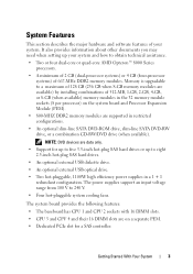
... An optional slim-line SATA DVD-ROM drive, slim-line SATA DVD-RW drive, or a combination CD-RW/DVD drive (when available). The power supplies support an input voltage range from 100 V to a maximum of 128 GB (256 GB when 8-GB memory modules are data only. •... drives. • An optional external USB diskette drive. • An optional external USB optical drive. • Two hot-pluggable, 1100W high efficiency power supplies in a 1 + 1 redundant configuration. It also provides information about other documents you may need when setting up to obtain technical assistance. •...
... An optional slim-line SATA DVD-ROM drive, slim-line SATA DVD-RW drive, or a combination CD-RW/DVD drive (when available). The power supplies support an input voltage range from 100 V to a maximum of 128 GB (256 GB when 8-GB memory modules are data only. •... drives. • An optional external USB diskette drive. • An optional external USB optical drive. • Two hot-pluggable, 1100W high efficiency power supplies in a 1 + 1 redundant configuration. It also provides information about other documents you may need when setting up to obtain technical assistance. •...
Getting Started Guide
Page 10
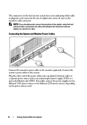
...and Monitor Power Cables Connect the monitor's power cable to the system. Connect the system's power cables to the monitor (optional). If possible, connect the power supplies to the front since only one display can operate at a time. The connectors on the back of the power cables into..., the video will default to two different 110V power sources or two different 220V power sources, depending on the monitor's cable connector. Be sure to plug into a grounded electrical outlet or a separate power source such as an uninterrupted power supply (UPS) or a power distribution unit (PDU).
...and Monitor Power Cables Connect the monitor's power cable to the system. Connect the system's power cables to the monitor (optional). If possible, connect the power supplies to the front since only one display can operate at a time. The connectors on the back of the power cables into..., the video will default to two different 110V power sources or two different 220V power sources, depending on the monitor's cable connector. Be sure to plug into a grounded electrical outlet or a separate power source such as an uninterrupted power supply (UPS) or a power distribution unit (PDU).
Getting Started Guide
Page 14
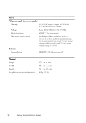
... inrush current Under typical line conditions and over the entire system ambient operating range, the inrush current may reach 55A per power supply for 10 ms or less and 35A per power supply for up to 150 ms. Batteries System battery CR 2032 3.0-V lithium coin cell Physical Height Width Depth Weight (maximum configuration) 17...
... inrush current Under typical line conditions and over the entire system ambient operating range, the inrush current may reach 55A per power supply for 10 ms or less and 35A per power supply for up to 150 ms. Batteries System battery CR 2032 3.0-V lithium coin cell Physical Height Width Depth Weight (maximum configuration) 17...
Hardware Owner's Manual (PDF)
Page 5
... a Cooling Fan 67 Replacing a Cooling Fan 68 Cooling Shroud Assembly 69 Removing the Cooling Shroud Assembly 69 Replacing the Cooling Shroud Assembly. . . . . . 70 Power Supplies 71 Removing a Power Supply 71 Replacing a Power Supply 72 Processor Expansion Module 73 Removing the PEM or PEM Shell 73 Replacing the PEM or PEM Shell 76 Expansion Cards 77 Expansion...
... a Cooling Fan 67 Replacing a Cooling Fan 68 Cooling Shroud Assembly 69 Removing the Cooling Shroud Assembly 69 Replacing the Cooling Shroud Assembly. . . . . . 70 Power Supplies 71 Removing a Power Supply 71 Replacing a Power Supply 72 Processor Expansion Module 73 Removing the PEM or PEM Shell 73 Replacing the PEM or PEM Shell 76 Expansion Cards 77 Expansion...
Hardware Owner's Manual (PDF)
Page 8
...Board 140 4 Troubleshooting Your System 143 Safety First-For You and Your System 143 Start-Up Routine 143 Checking Basic Power Problems 144 Checking the Equipment 144 Troubleshooting External Connections 144 Troubleshooting the Video Subsystem 145 Troubleshooting the Keyboard or Mouse....Troubleshooting a Wet System 152 Troubleshooting a Damaged System 152 Troubleshooting the System Battery 153 Troubleshooting Power Supplies 154 Troubleshooting System Cooling Problems 155 Troubleshooting a Fan 155 Troubleshooting System Memory 156 Troubleshooting an Optical Drive 158 8 Contents
...Board 140 4 Troubleshooting Your System 143 Safety First-For You and Your System 143 Start-Up Routine 143 Checking Basic Power Problems 144 Checking the Equipment 144 Troubleshooting External Connections 144 Troubleshooting the Video Subsystem 145 Troubleshooting the Keyboard or Mouse....Troubleshooting a Wet System 152 Troubleshooting a Damaged System 152 Troubleshooting the System Battery 153 Troubleshooting Power Supplies 154 Troubleshooting System Cooling Problems 155 Troubleshooting a Fan 155 Troubleshooting System Memory 156 Troubleshooting an Optical Drive 158 8 Contents
Hardware Owner's Manual (PDF)
Page 14
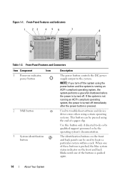
... only if directed to the system. NOTE: If you turn off . Figure 1-1. Front-Panel Features and Connectors Item Component Icon 1 Power-on the front and back panels can be used to locate a particular system within a rack. Used to troubleshoot software and device driver... of the buttons is pushed again. 14 About Your System The identification buttons on indicator, power button 2 NMI button 3 System identification button Description The power button controls the DC power supply output to do so by qualified support personnel or by the operating system's documentation. Front-...
... only if directed to the system. NOTE: If you turn off . Figure 1-1. Front-Panel Features and Connectors Item Component Icon 1 Power-on the front and back panels can be used to locate a particular system within a rack. Used to troubleshoot software and device driver... of the buttons is pushed again. 14 About Your System The identification buttons on indicator, power button 2 NMI button 3 System identification button Description The power button controls the DC power supply output to do so by qualified support personnel or by the operating system's documentation. Front-...
Hardware Owner's Manual (PDF)
Page 15
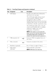
... lights during normal system operation. NOTE: If the system is connected to AC power and an error has been detected, the LCD display lights amber regardless of whether the system has been powered on the front and back of the system can cause the LCD to flash ...blue to identify a particular system. Connects USB 2.0-compliant devices to the system. 6 Video connector Connects a monitor to a problem with power supplies, fans, system temperature, or hard drives. Optional slimline optical drive NOTE: DVD devices are data only. About Your System 15 Table 1-2. Front-Panel ...
... lights during normal system operation. NOTE: If the system is connected to AC power and an error has been detected, the LCD display lights amber regardless of whether the system has been powered on the front and back of the system can cause the LCD to flash ...blue to identify a particular system. Connects USB 2.0-compliant devices to the system. 6 Video connector Connects a monitor to a problem with power supplies, fans, system temperature, or hard drives. Optional slimline optical drive NOTE: DVD devices are data only. About Your System 15 Table 1-2. Front-Panel ...
Hardware Owner's Manual (PDF)
Page 18
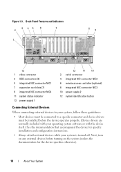
... (2) 5 integrated NIC connector NIC1 7 expansion-card slots (7) 9 integrated NIC connector NIC4 11 system status indicator 13 power supply 1 12 11 10 2 serial connector 4 integrated NIC connector NIC2 6 remote access controller (optional) 8 integrated NIC connector NIC3 10 power supply 2 12 system identification button Connecting External Devices When connecting external devices to your system, follow these...
... (2) 5 integrated NIC connector NIC1 7 expansion-card slots (7) 9 integrated NIC connector NIC4 11 system status indicator 13 power supply 1 12 11 10 2 serial connector 4 integrated NIC connector NIC2 6 remote access controller (optional) 8 integrated NIC connector NIC3 10 power supply 2 12 system identification button Connecting External Devices When connecting external devices to your system, follow these...
Hardware Owner's Manual (PDF)
Page 19
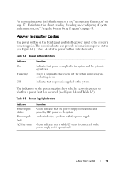
... The power button on power status (see Figure 1-1). Power Supply Indicators Indicator Power supply status Power supply fault AC line status Function Green indicates that no power is supplied to the power supply and is operational. The power indicator can provide information on the front panel controls the power input to the system and the system is supplied to the system. Table 1-4 lists the power button...
... The power button on power status (see Figure 1-1). Power Supply Indicators Indicator Power supply status Power supply fault AC line status Function Green indicates that no power is supplied to the power supply and is operational. The power indicator can provide information on the front panel controls the power input to the system and the system is supplied to the system. Table 1-4 lists the power button...
Hardware Owner's Manual (PDF)
Page 20
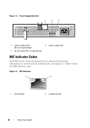
NIC Indicators 1 2 1 link indicator 2 activity indicator 20 About Your System Figure 1-5. See Figure 1-5. Power Supply Indicators 1 2 3 1 power supply status (DC out is operational) 3 AC line status (AC in is operational) 2 power supply fault NIC Indicator Codes Each NIC on the system back panel has an indicator that provides information on network activity and link status. Table 1-6 lists the NIC indicator codes. Figure 1-4.
NIC Indicators 1 2 1 link indicator 2 activity indicator 20 About Your System Figure 1-5. See Figure 1-5. Power Supply Indicators 1 2 3 1 power supply status (DC out is operational) 3 AC line status (AC in is operational) 2 power supply fault NIC Indicator Codes Each NIC on the system back panel has an indicator that provides information on network activity and link status. Table 1-6 lists the NIC indicator codes. Figure 1-4.
Hardware Owner's Manual (PDF)
Page 23
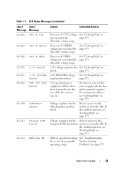
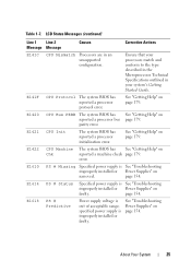
...failed. RPM of specified cooling See "Troubleshooting fan is out of acceptable System Cooling operating range. Problems" on . The specified power supply has failed or has been removed from the bay while the system was on page 155. Voltage regulator for the Recycle...page 179. Table 1-7. allowable voltage range Processor # VDDA See "Getting Help" on voltage has exceeded the page 179. Recycle power to power. If removed, reinsert the power supply into the bay and reconnect to the system or clear the SEL. About Your System 23 allowable voltage range 2.5V voltage regulator...
...failed. RPM of specified cooling See "Troubleshooting fan is out of acceptable System Cooling operating range. Problems" on . The specified power supply has failed or has been removed from the bay while the system was on page 155. Voltage regulator for the Recycle...page 179. Table 1-7. allowable voltage range Processor # VDDA See "Getting Help" on voltage has exceeded the page 179. Recycle power to power. If removed, reinsert the power supply into the bay and reconnect to the system or clear the SEL. About Your System 23 allowable voltage range 2.5V voltage regulator...
Hardware Owner's Manual (PDF)
Page 25
... 179. error. page 154. Ensure that your system's Getting Started Guide. parity error. See "Getting Help" on page 154. See "Troubleshooting Power Supplies" on page 179. E1610 PS # Missing Specified power supply is improperly installed or faulty. About Your System 25 E1421 CPU Init The system BIOS has reported a processor initialization error. E141F CPU...
... 179. error. page 154. Ensure that your system's Getting Started Guide. parity error. See "Getting Help" on page 154. See "Troubleshooting Power Supplies" on page 179. E1610 PS # Missing Specified power supply is improperly installed or faulty. About Your System 25 E1421 CPU Init The system BIOS has reported a processor initialization error. E141F CPU...
Hardware Owner's Manual (PDF)
Page 26
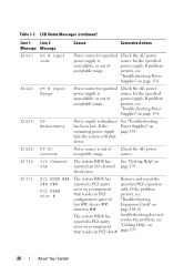
... "Troubleshooting has been lost. fails the system will shut down. E1620 PS # Input Range Power source for specified Check the AC power power supply is source for the specified unavailable, or out of power supply. If the Power Supplies" on page 154. Check the AC power source. See "Getting Help" on a component card. If the problem that resides in...
... "Troubleshooting has been lost. fails the system will shut down. E1620 PS # Input Range Power source for specified Check the AC power power supply is source for the specified unavailable, or out of power supply. If the Power Supplies" on page 154. Check the AC power source. See "Getting Help" on a component card. If the problem that resides in...
Hardware Owner's Manual (PDF)
Page 32
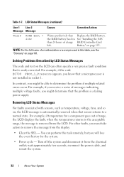
...E0708 PROC_1_Presence appears, you know that is easily corrected. You can often specify a very precise fault condition that a microprocessor is a failing power supply. NOTE: For the full name of messages indicating multiple voltage faults, you will lose the event history for a component goes out of ...; For example, if you receive a series of an abbreviation or acronym used in socket 1. wait approximately ten seconds, reconnect the power cable, and restart the system. 32 About Your System Solving Problems Described by LCD Status Messages The code and text on the LCD...
...E0708 PROC_1_Presence appears, you know that is easily corrected. You can often specify a very precise fault condition that a microprocessor is a failing power supply. NOTE: For the full name of messages indicating multiple voltage faults, you will lose the event history for a component goes out of ...; For example, if you receive a series of an abbreviation or acronym used in socket 1. wait approximately ten seconds, reconnect the power cable, and restart the system. 32 About Your System Solving Problems Described by LCD Status Messages The code and text on the LCD...
Hardware Owner's Manual (PDF)
Page 61
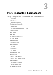
... This section describes how to install the following system components: • Front bezel • System cover • Cooling fan modules • Cooling shroud assembly • Power supplies • Processor expansion module (PEM) • Expansion cards • Riser board • RAC card • Internal USB memory key • TOE/iSCSI key • SD...
... This section describes how to install the following system components: • Front bezel • System cover • Cooling fan modules • Cooling shroud assembly • Power supplies • Processor expansion module (PEM) • Expansion cards • Riser board • RAC card • Internal USB memory key • TOE/iSCSI key • SD...
Hardware Owner's Manual (PDF)
Page 71
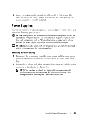
... is correctly installed. Installing System Components 71 See Figure 3-6. NOTICE: The system is fully seated. Power Supplies Your system supports two power supplies. The second power supply serves as PCI cards) not tested or supported by Dell are connected to an AC power source. For information about the cable management arm, see the system's Rack Installation Guide. 2 Gently...
... is correctly installed. Installing System Components 71 See Figure 3-6. NOTICE: The system is fully seated. Power Supplies Your system supports two power supplies. The second power supply serves as PCI cards) not tested or supported by Dell are connected to an AC power source. For information about the cable management arm, see the system's Rack Installation Guide. 2 Gently...
Hardware Owner's Manual (PDF)
Page 72
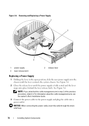
...Guide. 3 Connect the power cable to the power supply and plug the cable into place behind the lever release latch. NOTE: If you unlatched the cable management arm in the open position, slide the new power supply into the chassis until the power supply is fully seated and ...the lever snaps into a power outlet. NOTICE: When connecting the power cable, insert the cable through the strainrelief loop. 72 Installing System Components See...
...Guide. 3 Connect the power cable to the power supply and plug the cable into place behind the lever release latch. NOTE: If you unlatched the cable management arm in the open position, slide the new power supply into the chassis until the power supply is fully seated and ...the lever snaps into a power outlet. NOTICE: When connecting the power cable, insert the cable through the strainrelief loop. 72 Installing System Components See...
Hardware Owner's Manual (PDF)
Page 73
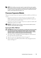
...Turn off the system, including any of processor expansion module assemblies used with your Product Information Guide for the system to signify that the power supply is fully disengaged from the electrical outlet. 2 Open the system. See "Opening the System" on page 65. 3 Lift the handle... on the PEM until the PEM is functioning properly (see Figure 1-4). The power-supply status indicator turns green to recognize the power supply and determine its status. See Figure 3-7 Installing System Components 73 See your system: • If you have a four-...
...Turn off the system, including any of processor expansion module assemblies used with your Product Information Guide for the system to signify that the power supply is fully disengaged from the electrical outlet. 2 Open the system. See "Opening the System" on page 65. 3 Lift the handle... on the PEM until the PEM is functioning properly (see Figure 1-4). The power-supply status indicator turns green to recognize the power supply and determine its status. See Figure 3-7 Installing System Components 73 See your system: • If you have a four-...


