
Glossary
Page 1
... Standards Institute. An individual code assigned to a system, usually by the DMTF. BMC - bus - A fast storage area that includes power supplies and fans. Centimeter(s). 1 Alternating current. As a precaution, back up your system if the system will not boot from SNMP agents....also contains an address bus and a data bus for security or tracking purposes. Advanced Configuration and Power Interface. bootable media - Certificate authority. Dell™ Glossary NOTE: For additional information on storage terminology, visit the Storage Networking Industry Association's ...
... Standards Institute. An individual code assigned to a system, usually by the DMTF. BMC - bus - A fast storage area that includes power supplies and fans. Centimeter(s). 1 Alternating current. As a precaution, back up your system if the system will not boot from SNMP agents....also contains an address bus and a data bus for security or tracking purposes. Advanced Configuration and Power Interface. bootable media - Certificate authority. Dell™ Glossary NOTE: For additional information on storage terminology, visit the Storage Networking Industry Association's ...

Glossary
Page 8
...USB memory key - Simple Network Management Protocol. System Setup program - An unregistered (unbuffered) DDR3 memory module. Uninterruptible power supply. See also guarding, mirroring, and RAID. Super video graphics array. VGA and SVGA are connected in the configuration software... until you to I/O devices. uplink port - A BIOS-based program that automatically supplies power to remotely monitor and manage workstations. TOE - striping - TCP/IP - A battery-powered unit that allows you change them again. Universal Serial Bus. Symmetric multiprocessing. A ...
...USB memory key - Simple Network Management Protocol. System Setup program - An unregistered (unbuffered) DDR3 memory module. Uninterruptible power supply. See also guarding, mirroring, and RAID. Super video graphics array. VGA and SVGA are connected in the configuration software... until you to I/O devices. uplink port - A BIOS-based program that automatically supplies power to remotely monitor and manage workstations. TOE - striping - TCP/IP - A battery-powered unit that allows you change them again. Universal Serial Bus. Symmetric multiprocessing. A ...

Glossary
Page 48
...; SVGA W - Windows Management Instrumentation。CIM ZIF - Self-Monitoring Analysis and Reporting Technology BIOS SMP - Simple Network Management Protocol SVGA - Volt direct current VGA - Uninterruptible power supply USB - Zero insertion force 48 SMART - Unregistered DDR3 UPS -
...; SVGA W - Windows Management Instrumentation。CIM ZIF - Self-Monitoring Analysis and Reporting Technology BIOS SMP - Simple Network Management Protocol SVGA - Volt direct current VGA - Uninterruptible power supply USB - Zero insertion force 48 SMART - Unregistered DDR3 UPS -

Glossary
Page 58
TCP/IP TCP/IP Offload Engine U-DIMM DDR3 Unregistered(Unbuffered) DDR3 Memory Module UPS Uninterruptible Power Supply USB Universal Serial Bus USB USB USB USB V - 볼트 (Volt VAC Volt Alternating Current VDC Volt Direct Current VGA Video Graphics Array VGA 와 ...; SVGA TCP/IP Transmission Control Protocol/Internet Protocol TOE - Windows Management Instrumentation 은 CIM ZIF Zero Insertion Force provider CIM management station managed system) 은 Dell OpenManage™ Server Administrator x x y x z 58
TCP/IP TCP/IP Offload Engine U-DIMM DDR3 Unregistered(Unbuffered) DDR3 Memory Module UPS Uninterruptible Power Supply USB Universal Serial Bus USB USB USB USB V - 볼트 (Volt VAC Volt Alternating Current VDC Volt Direct Current VGA Video Graphics Array VGA 와 ...; SVGA TCP/IP Transmission Control Protocol/Internet Protocol TOE - Windows Management Instrumentation 은 CIM ZIF Zero Insertion Force provider CIM management station managed system) 은 Dell OpenManage™ Server Administrator x x y x z 58

Information Update - Power Infrastructure Sizing
Page 1
... software provide additional predictability for infrastructure sizing. Systems characterized while using the power capping features enabled from Dell may result in an infrastructure that is utilized less than that of Power Distribution Units (PDUs), Uninterruptible Power Supplies (UPSs), and other power infrastructure distribution equipment. Example: If a server power supply is used for the configuration and workload, the 500W...
... software provide additional predictability for infrastructure sizing. Systems characterized while using the power capping features enabled from Dell may result in an infrastructure that is utilized less than that of Power Distribution Units (PDUs), Uninterruptible Power Supplies (UPSs), and other power infrastructure distribution equipment. Example: If a server power supply is used for the configuration and workload, the 500W...

Getting Started Guide
Page 7
Turning On the System Press the power button on the system and the monitor. Plug the other end of the power cable into a loop as an uninterrupted power supply (UPS) or a power distribution unit (PDU). Getting Started With Your System 5 The power indicators should light. Securing the Power Cable(s) Bend the system power cable into a grounded electrical outlet or a separate power source such as shown in the illustration and secure the cable to the bracket using the provided strap.
Turning On the System Press the power button on the system and the monitor. Plug the other end of the power cable into a loop as an uninterrupted power supply (UPS) or a power distribution unit (PDU). Getting Started With Your System 5 The power indicators should light. Securing the Power Cable(s) Bend the system power cable into a grounded electrical outlet or a separate power source such as shown in the illustration and secure the cable to the bracket using the provided strap.
Getting Started Guide
Page 13
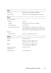
Video Video type Video memory Power AC power supply Wattage Voltage Heat dissipation Maximum inrush current Batteries System battery Physical Height Width Depth Weight (maximum configuration) Weight (empty) Integrated Matrox G200 with iDRAC6 8 MB (... Hz, auto-ranging 4012 BTU/Hr Under typical line conditions and over the entire system ambient operating range, the inrush current may reach 55 A per power supply for 10 ms or less CR 2032 3.0-V lithium coin cell 8.64 cm (3.40 in) 44.05 cm (17.34 in) without bezel 48.24 cm...
Video Video type Video memory Power AC power supply Wattage Voltage Heat dissipation Maximum inrush current Batteries System battery Physical Height Width Depth Weight (maximum configuration) Weight (empty) Integrated Matrox G200 with iDRAC6 8 MB (... Hz, auto-ranging 4012 BTU/Hr Under typical line conditions and over the entire system ambient operating range, the inrush current may reach 55 A per power supply for 10 ms or less CR 2032 3.0-V lithium coin cell 8.64 cm (3.40 in) 44.05 cm (17.34 in) without bezel 48.24 cm...
Hardware Owner's Manual
Page 5
... a Hard-Drive Carrier 82 Installing a Hard Drive Into a Hard-Drive Carrier 82 Optical Drive 83 Removing an Optical Drive 83 Installing an Optical Drive 84 Power Supplies 85 Removing a Power Supply 85 Installing a Power Supply 87 Contents 5
... a Hard-Drive Carrier 82 Installing a Hard Drive Into a Hard-Drive Carrier 82 Optical Drive 83 Removing an Optical Drive 83 Installing an Optical Drive 84 Power Supplies 85 Removing a Power Supply 85 Installing a Power Supply 87 Contents 5

Hardware Owner's Manual
Page 6
Removing the Power Supply Blank 87 Installing the Power Supply Blank 87 Cooling Shroud 88 Removing the Cooling Shroud 88 Installing the Cooling Shroud 89 Front-Chassis Assembly 90 System Memory 92 General Memory Module ...
Removing the Power Supply Blank 87 Installing the Power Supply Blank 87 Cooling Shroud 88 Removing the Cooling Shroud 88 Installing the Cooling Shroud 89 Front-Chassis Assembly 90 System Memory 92 General Memory Module ...

Hardware Owner's Manual
Page 8
... Troubleshooting a USB Device 152 Troubleshooting a Serial I/O Device 153 Troubleshooting a NIC 153 Troubleshooting a Wet System 154 Troubleshooting a Damaged System 155 Troubleshooting the System Battery 156 Troubleshooting Power Supplies 157 Troubleshooting System Cooling Problems 157 Troubleshooting a Fan 158 Troubleshooting System Memory 159 8 Contents
... Troubleshooting a USB Device 152 Troubleshooting a Serial I/O Device 153 Troubleshooting a NIC 153 Troubleshooting a Wet System 154 Troubleshooting a Damaged System 155 Troubleshooting the System Battery 156 Troubleshooting Power Supplies 157 Troubleshooting System Cooling Problems 157 Troubleshooting a Fan 158 Troubleshooting System Memory 159 8 Contents

Hardware Owner's Manual
Page 12
... a graceful shutdown before power to the system is not accessible. NOTE: When powering on the system, the video monitor can take from several seconds to over two minutes to the system. The power button controls the DC power supply output to display an image..., depending on . Front-Panel Features and Indicators Figure 1-1. Front-Panel Features and Indicators 1 2 3 4 5 6 7 8 9 10 Item Indicator, Button, or Icon Connector 1 Power-on indicator, power button Description The power-on indicator lights when the system power...
... a graceful shutdown before power to the system is not accessible. NOTE: When powering on the system, the video monitor can take from several seconds to over two minutes to the system. The power button controls the DC power supply output to display an image..., depending on . Front-Panel Features and Indicators Figure 1-1. Front-Panel Features and Indicators 1 2 3 4 5 6 7 8 9 10 Item Indicator, Button, or Icon Connector 1 Power-on indicator, power button Description The power-on indicator lights when the system power...

Hardware Owner's Manual
Page 19
...low-profile 24.13 cm [9.5"] length). PCI Express (Generation 2) x8 link expansion slot (24.13 cm [9.5"] length). 1100 W power supplies. Lights amber when the system needs attention due to locate a particular system within a rack. Integrated 10/100/1000 NIC connectors. ...or Icon Connector 1 PCIe slot 1 2 PCIe slot 2 3 PCIe slot 3 4 PCIe slot 4 5 PCIe slot 5 6 PCIe slot 6 7 Power supplies (2) 8 System identification button 9 System status indicator 10 System identification connector 11 Ethernet connectors (4) Description PCI Express (Generation 2) x8 link expansion slot (24....
...low-profile 24.13 cm [9.5"] length). PCI Express (Generation 2) x8 link expansion slot (24.13 cm [9.5"] length). 1100 W power supplies. Lights amber when the system needs attention due to locate a particular system within a rack. Integrated 10/100/1000 NIC connectors. ...or Icon Connector 1 PCIe slot 1 2 PCIe slot 2 3 PCIe slot 3 4 PCIe slot 4 5 PCIe slot 5 6 PCIe slot 6 7 Power supplies (2) 8 System identification button 9 System status indicator 10 System identification connector 11 Ethernet connectors (4) Description PCI Express (Generation 2) x8 link expansion slot (24....

Hardware Owner's Manual
Page 21
.... Power Indicator Codes The power supplies have indicators that show whether power is present or whether a power fault has occurred. • Not lit-AC power is not connected. • Green-In standby mode, a green light indicates that the power supply is operational. When the system is on, a green light also indicates that the power supply is providing DC power to the power supply...
.... Power Indicator Codes The power supplies have indicators that show whether power is present or whether a power fault has occurred. • Not lit-AC power is not connected. • Green-In standby mode, a green light indicates that the power supply is operational. When the system is on, a green light also indicates that the power supply is providing DC power to the power supply...

Hardware Owner's Manual
Page 22
Press the left and right buttons to highlight an error number, and press Select to events recorded in the System Event Log (SEL). Power Supply Status Indicator 1 1 power supply status indicator LCD Status Messages The LCD messages consist of errors or status messages. Press the Select button to boot, press the System ID button ...
Press the left and right buttons to highlight an error number, and press Select to events recorded in the System Event Log (SEL). Power Supply Status Indicator 1 1 power supply status indicator LCD Status Messages The LCD messages consist of errors or status messages. Press the Select button to boot, press the System ID button ...

Hardware Owner's Manual
Page 27
..." on condition, or power supply page 157. Check power supply. A power supply fan failure, See "Troubleshooting an over-temperature Power Supplies" on page 185. Specified power supply is missing from the system. Check the AC power source for 10 seconds and error. Check power supply. See "Troubleshooting Power Supplies" on Power Supply # (#### W). communication error caused the predictive warning of an impending power supply failure. Specified power supply removed or is installed...
..." on condition, or power supply page 157. Check power supply. A power supply fan failure, See "Troubleshooting an over-temperature Power Supplies" on page 185. Specified power supply is missing from the system. Check the AC power source for 10 seconds and error. Check power supply. See "Troubleshooting Power Supplies" on Power Supply # (#### W). communication error caused the predictive warning of an impending power supply failure. Specified power supply removed or is installed...

Hardware Owner's Manual
Page 28
... the specified allowable range. If the problem persists, see "Getting Help" on the System power requirements. If Power Supplies" on page 157. E1629 Power required > PSU wattage. Contact support. E1624 Lost power supply redundancy. Contact support. consumption below the maximum safe level with current power supply configuration. E1632 FailSafe event. below the maximum safe level with throttling. Specified...
... the specified allowable range. If the problem persists, see "Getting Help" on the System power requirements. If Power Supplies" on page 157. E1629 Power required > PSU wattage. Contact support. E1624 Lost power supply redundancy. Contact support. consumption below the maximum safe level with current power supply configuration. E1632 FailSafe event. below the maximum safe level with throttling. Specified...

Hardware Owner's Manual
Page 37
... RAID battery has less than charge to greater than 24 24 hours of sustained charge. hours of charge left. W1630 Power supply redundancy degraded. Check PSU cables. If the problem persists, see "Getting Help" on page 185. If the problem ...dell.com/manuals. See "Internal Dual SD Module (Optional)" on page 185. Check fans. is no longer fully redundant. NOTE: For the full name of an abbreviation or acronym used in this table, see "Getting Help" on page 123. See "Troubleshooting System Cooling Problems" on page 157. The power supply subsystem Reseat the power supplies...
... RAID battery has less than charge to greater than 24 24 hours of sustained charge. hours of charge left. W1630 Power supply redundancy degraded. Check PSU cables. If the problem persists, see "Getting Help" on page 185. If the problem ...dell.com/manuals. See "Internal Dual SD Module (Optional)" on page 185. Check fans. is no longer fully redundant. NOTE: For the full name of an abbreviation or acronym used in this table, see "Getting Help" on page 123. See "Troubleshooting System Cooling Problems" on page 157. The power supply subsystem Reseat the power supplies...

Hardware Owner's Manual
Page 39
... not support redundant memory. Ensure that the memory modules are installed, replace them with this power supply. Check other system messages for additional information for failure. See "Power Supplies" on page 159. See "Troubleshooting System Memory" on page 85. About Your System 39...has failed) so that supports node interleaving. Alert! Continuing system boot accepts the risk that system may be supported by the power supplies. If any system components were just upgraded, return the system to use the components. Memory configuration does not support Node ...
... not support redundant memory. Ensure that the memory modules are installed, replace them with this power supply. Check other system messages for additional information for failure. See "Power Supplies" on page 159. See "Troubleshooting System Memory" on page 85. About Your System 39...has failed) so that supports node interleaving. Alert! Continuing system boot accepts the risk that system may be supported by the power supplies. If any system components were just upgraded, return the system to use the components. Memory configuration does not support Node ...

Hardware Owner's Manual
Page 49
... subsystem. About Your System 49 Check PSU and system configuration. System will reboot. Incorrect memory configuration CPU n. See "Power Supplies" on page 159. CPU and memory set to minimum frequencies to the previous configuration. If any system components were just... PSU wattage. cables are not supported with High Output power supplies to halt. Message Causes Corrective Actions Warning! Warning! Power required exceeds PSU wattage. If the system boots without this power supply. The system configuration of processor(s), memory modules, and expansion...
... subsystem. About Your System 49 Check PSU and system configuration. System will reboot. Incorrect memory configuration CPU n. See "Power Supplies" on page 159. CPU and memory set to minimum frequencies to the previous configuration. If any system components were just... PSU wattage. cables are not supported with High Output power supplies to halt. Message Causes Corrective Actions Warning! Warning! Power required exceeds PSU wattage. If the system boots without this power supply. The system configuration of processor(s), memory modules, and expansion...

Hardware Owner's Manual
Page 74
Figure 3-1. Inside the System 12 11 10 1 2 3 4 9 8 7 1 cooling shroud 3 expansion card riser 2 5 heat sinks (2 or 4) 7 hard drives (up to 6) 9 optical drive (optional) 11 cooling fan assembly 5 6 2 power supply bays (2) 4 expansion card riser 1 6 memory modules (8 to 32) 8 control panel 10 SD module 12 cooling fans (6) 74 Installing System Components
Figure 3-1. Inside the System 12 11 10 1 2 3 4 9 8 7 1 cooling shroud 3 expansion card riser 2 5 heat sinks (2 or 4) 7 hard drives (up to 6) 9 optical drive (optional) 11 cooling fan assembly 5 6 2 power supply bays (2) 4 expansion card riser 1 6 memory modules (8 to 32) 8 control panel 10 SD module 12 cooling fans (6) 74 Installing System Components


