
Glossary
Page 2
...power indicator. expansion bus - The part of data between the processor and memory or between the expansion bus and a peripheral. 2 device driver - DRAM - A system's RAM is usually made up entirely of tests for the serial ports on both the rising and falling pulses of... translating Internet domain names, such as www.example.com, into an expansion-card connector on your network server using a remote access controller. driver - ESM - An expansion card adds some other program to the system by transferring data on your system. Embedded server management. DC -...
...power indicator. expansion bus - The part of data between the processor and memory or between the expansion bus and a peripheral. 2 device driver - DRAM - A system's RAM is usually made up entirely of tests for the serial ports on both the rising and falling pulses of... translating Internet domain names, such as www.example.com, into an expansion-card connector on your network server using a remote access controller. driver - ESM - An expansion card adds some other program to the system by transferring data on your system. Embedded server management. DC -...
Glossary
Page 9
.... The logical circuitry that plugs into an expansion slot. Volt(s) alternating current. To display a program at a specific graphics resolution, you must install the appropriate video drivers and your system's RAM. Volt(s). VDC - The ability via software to your monitor must support the resolution. WH - The amount of video memory installed primarily..., for example) is expressed as multiple virtual systems able to manage system resources-memory, disk drives, or printers, for video adapters with the appropriate video drivers and monitor capabilities). utility -
.... The logical circuitry that plugs into an expansion slot. Volt(s) alternating current. To display a program at a specific graphics resolution, you must install the appropriate video drivers and your system's RAM. Volt(s). VDC - The ability via software to your monitor must support the resolution. WH - The amount of video memory installed primarily..., for example) is expressed as multiple virtual systems able to manage system resources-memory, disk drives, or printers, for video adapters with the appropriate video drivers and monitor capabilities). utility -
Hardware Owner's Manual
Page 13
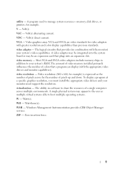
... Connector 2 NMI button 3 USB connectors (2) 4 Video connector 5 System identification panel 6 LCD menu buttons 7 LCD panel 8 System identification button Description Used to troubleshoot software and device driver errors when using the end of a paper clip.
... Connector 2 NMI button 3 USB connectors (2) 4 Video connector 5 System identification panel 6 LCD menu buttons 7 LCD panel 8 System identification button Description Used to troubleshoot software and device driver errors when using the end of a paper clip.

Hardware Owner's Manual
Page 20
... power to the system and external devices before turning on the system (unless the documentation for the device specifies otherwise). • Ensure that the appropriate driver for the attached device has been installed on the system. • If it is necessary to enable ports on your system, see "Using the System...
... power to the system and external devices before turning on the system (unless the documentation for the device specifies otherwise). • Ensure that the appropriate driver for the attached device has been installed on the system. • If it is necessary to enable ports on your system, see "Using the System...

Hardware Owner's Manual
Page 73
... You may only be done by the online or telephone service and support team. Read and follow the safety instructions that is not authorized by Dell is recommended that you need the following items to perform the procedures in this section: • Key to the system keylock • #1... and #2 Phillips screwdrivers • T8 and T10 Torx drivers • Wrist grounding strap Inside the System WARNING: Whenever you always use a static mat and static strap while working on components in your warranty. ...
... You may only be done by the online or telephone service and support team. Read and follow the safety instructions that is not authorized by Dell is recommended that you need the following items to perform the procedures in this section: • Key to the system keylock • #1... and #2 Phillips screwdrivers • T8 and T10 Torx drivers • Wrist grounding strap Inside the System WARNING: Whenever you always use a static mat and static strap while working on components in your warranty. ...

Hardware Owner's Manual
Page 110
... system and aid in proper cooling and airflow inside the system. 8 Close the system. Read and follow the safety instructions that is not authorized by Dell is not covered by its edges, and carefully remove it from the card. 4 Lift the expansion-card latch. See "Closing the System" on page 77...
... system and aid in proper cooling and airflow inside the system. 8 Close the system. Read and follow the safety instructions that is not authorized by Dell is not covered by its edges, and carefully remove it from the card. 4 Lift the expansion-card latch. See "Closing the System" on page 77...
Hardware Owner's Manual
Page 139
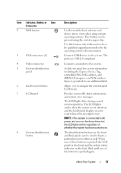
...If installed, remove the front bezel. See Figure 3-29. 6 Bend the panel upward to access to the mounting screws. 7 Using a T10 Torx driver, remove the two screws that secure the display module to the system. 8 Remove the display module from the electrical outlet. 3 Open the system. Read... and follow the safety instructions that is not authorized by Dell is not covered by your product documentation, or as directed by a certified service technician. Damage due to lift the panel outward. Installing ...
...If installed, remove the front bezel. See Figure 3-29. 6 Bend the panel upward to access to the mounting screws. 7 Using a T10 Torx driver, remove the two screws that secure the display module to the system. 8 Remove the display module from the electrical outlet. 3 Open the system. Read... and follow the safety instructions that is not authorized by Dell is not covered by your product documentation, or as directed by a certified service technician. Damage due to lift the panel outward. Installing ...
Hardware Owner's Manual
Page 142
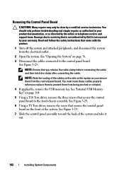
...and disconnect the system from being pinched or crimped. 4 If applicable, remove the USB memory key. NOTE: Ensure that is not authorized by Dell is not covered by a certified service technician. You must route these cables properly when you replace them to servicing that you remove them from the... panel board. See Figure 3-29. 7 Slide the control panel assembly toward the back of the system. See Figure 3-29. 6 Using a T8 Torx driver, remove the screw that secure the control panel board to the control panel board. Removing the Control Panel Board CAUTION: Many repairs may only be...
...and disconnect the system from being pinched or crimped. 4 If applicable, remove the USB memory key. NOTE: Ensure that is not authorized by Dell is not covered by a certified service technician. You must route these cables properly when you replace them to servicing that you remove them from the... panel board. See Figure 3-29. 7 Slide the control panel assembly toward the back of the system. See Figure 3-29. 6 Using a T8 Torx driver, remove the screw that secure the control panel board to the control panel board. Removing the Control Panel Board CAUTION: Many repairs may only be...
Hardware Owner's Manual
Page 143
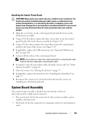
... the product. 1 Align the screw holes on the control panel board with the holes on the front-chassis assembly. 2 Using a T10 Torx driver, replace the three screws that secures the control panel board on the front of the system. See Figure 3-29. 3 Using a T8 Torx.... 4 If applicable, replace the USB memory key. See "Closing the System" on , including any attached peripherals. NOTE: Ensure that is not authorized by Dell is divided into two boards, which are interconnected by your product documentation, or as directed by a certified service technician. Damage due to the front-chassis...
... the product. 1 Align the screw holes on the control panel board with the holes on the front-chassis assembly. 2 Using a T10 Torx driver, replace the three screws that secures the control panel board on the front of the system. See Figure 3-29. 3 Using a T8 Torx.... 4 If applicable, replace the USB memory key. See "Closing the System" on , including any attached peripherals. NOTE: Ensure that is not authorized by Dell is divided into two boards, which are interconnected by your product documentation, or as directed by a certified service technician. Damage due to the front-chassis...

Hardware Owner's Manual
Page 151
... cable, and power up the device. If all cable connections. • If the activity indicator does not light, the network driver files might be damaged or missing. Remove and reinstall the drivers if applicable. If the problem is resolved, replace the interface cable. 3 Turn off the system and any system messages pertaining...
... cable, and power up the device. If all cable connections. • If the activity indicator does not light, the network driver files might be damaged or missing. Remove and reinstall the drivers if applicable. If the problem is resolved, replace the interface cable. 3 Turn off the system and any system messages pertaining...
Hardware Owner's Manual
Page 152
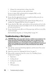
...the system. Damage due to the same data transmission speed and duplex mode. Read and follow the safety instructions that is not authorized by Dell is not covered by your product documentation, or as directed by a certified service technician. Troubleshooting a Wet System CAUTION: Many repairs may ... and support team. See "Opening the System" on page 185. See "Integrated Devices Screen" on page 60. 6 Ensure that the appropriate drivers are installed and the protocols are all network cables are enabled. See the documentation for the NIC card. 4 Ensure that the NICs, hubs,...
...the system. Damage due to the same data transmission speed and duplex mode. Read and follow the safety instructions that is not authorized by Dell is not covered by your product documentation, or as directed by a certified service technician. Troubleshooting a Wet System CAUTION: Many repairs may ... and support team. See "Opening the System" on page 185. See "Integrated Devices Screen" on page 60. 6 Ensure that the appropriate drivers are installed and the protocols are all network cables are enabled. See the documentation for the NIC card. 4 Ensure that the NICs, hubs,...
Hardware Owner's Manual
Page 163
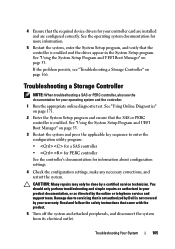
...System Setup Program and UEFI Boot Manager" on page 171. 2 Enter the System Setup program and ensure that is not authorized by Dell is not covered by your operating system and the controller. 1 Run the appropriate online diagnostic test. You should only perform troubleshooting ... See the operating system documentation for your product documentation, or as directed by a certified service technician. 4 Ensure that the required device drivers for more information. 5 Restart the system, enter the System Setup program, and verify that the controller is enabled and the drives appear...
...System Setup Program and UEFI Boot Manager" on page 171. 2 Enter the System Setup program and ensure that is not authorized by Dell is not covered by your operating system and the controller. 1 Run the appropriate online diagnostic test. You should only perform troubleshooting ... See the operating system documentation for your product documentation, or as directed by a certified service technician. 4 Ensure that the required device drivers for more information. 5 Restart the system, enter the System Setup program, and verify that the controller is enabled and the drives appear...


