
Glossary
Page 2
... in memory modules that potentially doubles the data rate by providing an interface between the processor and a peripheral device. A method of automatically assigning an IP address to interface correctly with controllers for the serial ports on your network server using a remote access controller. DIMM - DRAM - Digital versatile disc or digital video disc. Electrostatic discharge. COMn - A chip that contains indicators and controls, such as the power button and power indicator. CPU - Double-data rate. device driver - A comprehensive set of specific...
... in memory modules that potentially doubles the data rate by providing an interface between the processor and a peripheral device. A method of automatically assigning an IP address to interface correctly with controllers for the serial ports on your network server using a remote access controller. DIMM - DRAM - Digital versatile disc or digital video disc. Electrostatic discharge. COMn - A chip that contains indicators and controls, such as the power button and power indicator. CPU - Double-data rate. device driver - A comprehensive set of specific...

Glossary
Page 3
... offers point-to hard-drive capacity, the term is an output device. Internet Protocol. File allocation table. Fibre Channel - A type of processors with networked storage devices. Gram(s). Gb - However, when referring to -point bidirectional serial links intended for plugging in an expansion card. host adapter - A controller that can be differentiated from computational activity. Integrated drive electronics. Internet Protocol version 6. 3 F - A high-speed network interface used by z colors. FSB - Gravities. hot-plug - FAT...
... offers point-to hard-drive capacity, the term is an output device. Internet Protocol. File allocation table. Fibre Channel - A type of processors with networked storage devices. Gram(s). Gb - However, when referring to -point bidirectional serial links intended for plugging in an expansion card. host adapter - A controller that can be differentiated from computational activity. Integrated drive electronics. Internet Protocol version 6. 3 F - A high-speed network interface used by z colors. FSB - Gravities. hot-plug - FAT...

Glossary
Page 7
...'s documentation. A standard interface between the system board and storage devices. SCSI - A text file, usually shipped with faster data transmission rates than standard ports. A read -only file - RAID - Redundant array of RAID include RAID 0, RAID 1, RAID 5, RAID 10, and RAID 50. A method of code in ROM code. A registered DDR3 memory module. A ROM chip retains its operation in ROM include the program that you turn off your system's boot routine and the POST. Secure digital flash memory card. Synchronous dynamic random-access memory. System event log. SMART...
...'s documentation. A standard interface between the system board and storage devices. SCSI - A text file, usually shipped with faster data transmission rates than standard ports. A read -only file - RAID - Redundant array of RAID include RAID 0, RAID 1, RAID 5, RAID 10, and RAID 50. A method of code in ROM code. A registered DDR3 memory module. A ROM chip retains its operation in ROM include the program that you turn off your system's boot routine and the POST. Secure digital flash memory card. Synchronous dynamic random-access memory. System event log. SMART...

Glossary
Page 8
... memory module. Simple Network Management Protocol. SVGA - system memory - A USB connector provides a single connection point for peripherals, and various ROM chips. Disk striping writes data across three or more processors connected via a high-bandwidth link and managed by setting features such as the last device at each disk used to connect to I/O devices. See also guarding, mirroring, and RAID. system board - termination - USB devices can be configured for the devices. USB - TCP/IP offload engine. A battery-powered unit that automatically supplies power...
... memory module. Simple Network Management Protocol. SVGA - system memory - A USB connector provides a single connection point for peripherals, and various ROM chips. Disk striping writes data across three or more processors connected via a high-bandwidth link and managed by setting features such as the last device at each disk used to connect to I/O devices. See also guarding, mirroring, and RAID. system board - termination - USB devices can be configured for the devices. USB - TCP/IP offload engine. A battery-powered unit that automatically supplies power...
Hardware Owner's Manual
Page 26
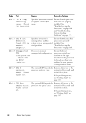
... restart the system. Specified processor is Ensure that your processors match and conform to the type described in the processor technical specifications outlined in your system's Getting Started Guide. If the problem persists, see "Getting Help" on page 185. The system BIOS reported a Remove AC power to the processor bus parity error. Check CPU is in an CPU unsupported configuration. Power cycle AC. installed. Check CPU or BIOS revision. If the problem persists, see "Getting...
... restart the system. Specified processor is Ensure that your processors match and conform to the type described in the processor technical specifications outlined in your system's Getting Started Guide. If the problem persists, see "Getting Help" on page 185. The system BIOS reported a Remove AC power to the processor bus parity error. Check CPU is in an CPU unsupported configuration. Power cycle AC. installed. Check CPU or BIOS revision. If the problem persists, see "Getting...

Hardware Owner's Manual
Page 27
... CPU # machine check error. Power cycle AC. See "Troubleshooting Power Supplies" on condition, or power supply page 157. Check power supply. A power supply fan failure, See "Troubleshooting an over-temperature Power Supplies" on page 157. Specified power supply is missing from the system. If the problem persists, see "Getting Help" on page 185. The system BIOS reported a Remove AC power to the initialization processor initialization error. If the problem persists, see "Getting Help" on page 157. Specified power supply removed or is installed...
... CPU # machine check error. Power cycle AC. See "Troubleshooting Power Supplies" on condition, or power supply page 157. Check power supply. A power supply fan failure, See "Troubleshooting an over-temperature Power Supplies" on page 157. Specified power supply is missing from the system. If the problem persists, see "Getting Help" on page 185. The system BIOS reported a Remove AC power to the initialization processor initialization error. If the problem persists, see "Getting Help" on page 157. Specified power supply removed or is installed...

Hardware Owner's Manual
Page 32
... Control panel USB cable to the control USB cable not panel is redundancy no longer redundant. detected. Reseat the cable. If the problem persists, replace the cable. If the problem persists, see "Getting Help" on page 185. 32 About Your System Check SD cards. SAS cable B is writeprotected and cannot be used. If the problem persists, see "Getting Help" on page 185. The internal dual SD module card is missing or bad. E1A14 SAS cable A failure. Check connection. Check cable. Check...
... Control panel USB cable to the control USB cable not panel is redundancy no longer redundant. detected. Reseat the cable. If the problem persists, replace the cable. If the problem persists, see "Getting Help" on page 185. 32 About Your System Check SD cards. SAS cable B is writeprotected and cannot be used. If the problem persists, see "Getting Help" on page 185. The internal dual SD module card is missing or bad. E1A14 SAS cable A failure. Check connection. Check cable. Check...

Hardware Owner's Manual
Page 36
... system BIOS disabled Reseat the memory memory single-bit error module in its socket. (SBE) logging and will not If the problem persists, log any more SBEs until the see "Troubleshooting System Memory" on the LCD. module implicated by the BIOS. E2112 Memory spared on represents the memory page 159. Power cycle AC. memory has too many errors. "##" System Memory" on Card x DIMM ##. System cover removed. I1911 LCD Log Full. Remove AC power to review all Errors. error (MBE). Replace the chassis cover...
... system BIOS disabled Reseat the memory memory single-bit error module in its socket. (SBE) logging and will not If the problem persists, log any more SBEs until the see "Troubleshooting System Memory" on the LCD. module implicated by the BIOS. E2112 Memory spared on represents the memory page 159. Power cycle AC. memory has too many errors. "##" System Memory" on Card x DIMM ##. System cover removed. I1911 LCD Log Full. Remove AC power to review all Errors. error (MBE). Replace the chassis cover...

Hardware Owner's Manual
Page 49
...page 85. Check PSU and system configuration. The system configuration of processor(s), memory modules, and expansion cards may not be supported by the power supplies. Faulty USB device, USB Replace the USB medium or medium, optical drive device. See "Power Supplies" on page 159. See "Troubleshooting a USB Device" on page 152, "Troubleshooting an Internal USB Key" on page 161, and "Troubleshooting a Hard Drive" on page 93, for CPU n See "General Memory is incorrectly configured and Module Installation caused the system to use the components. CPU and memory set to...
...page 85. Check PSU and system configuration. The system configuration of processor(s), memory modules, and expansion cards may not be supported by the power supplies. Faulty USB device, USB Replace the USB medium or medium, optical drive device. See "Power Supplies" on page 159. See "Troubleshooting a USB Device" on page 152, "Troubleshooting an Internal USB Key" on page 161, and "Troubleshooting a Hard Drive" on page 93, for CPU n See "General Memory is incorrectly configured and Module Installation caused the system to use the components. CPU and memory set to...
Hardware Owner's Manual
Page 53
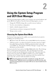
... installed from the UEFI boot mode. Using the System Setup Program and UEFI Boot Manager 53 NOTE: Operating systems must select the boot mode in that overlays the system BIOS. DOS and 32-bit operating systems do not support UEFI and can : • Change the NVRAM settings after you add or remove hardware • View the system hardware configuration • Enable or disable integrated devices • Set performance and power management thresholds • Manage system security Choosing the System Boot Mode The System Setup program also enables...
... installed from the UEFI boot mode. Using the System Setup Program and UEFI Boot Manager 53 NOTE: Operating systems must select the boot mode in that overlays the system BIOS. DOS and 32-bit operating systems do not support UEFI and can : • Change the NVRAM settings after you add or remove hardware • View the system hardware configuration • Enable or disable integrated devices • Set performance and power management thresholds • Manage system security Choosing the System Boot Mode The System Setup program also enables...

Hardware Owner's Manual
Page 59
...Mode enables the integrated SATA controller. If Boot Mode is set to boot from booting if the operating system was not installed in the same boot mode. Using the System Setup Program and UEFI Boot Manager 59 If Boot Mode is set to UEFI disables the Boot Sequence, Hard-Disk Drive Sequence, and USB Flash Drive Emulation Type fields. Off disables BIOS support for a USB flash drive. Boot Settings Screen Option Boot Mode (BIOS default) Boot Sequence Hard-Disk Drive Sequence USB Flash Drive Emulation Type Boot Sequence Retry (Disabled default) Description CAUTION: Switching the boot...
...Mode enables the integrated SATA controller. If Boot Mode is set to boot from booting if the operating system was not installed in the same boot mode. Using the System Setup Program and UEFI Boot Manager 59 If Boot Mode is set to UEFI disables the Boot Sequence, Hard-Disk Drive Sequence, and USB Flash Drive Emulation Type fields. Off disables BIOS support for a USB flash drive. Boot Settings Screen Option Boot Mode (BIOS default) Boot Sequence Hard-Disk Drive Sequence USB Flash Drive Emulation Type Boot Sequence Retry (Disabled default) Description CAUTION: Switching the boot...

Hardware Owner's Manual
Page 60
... NICs. Embedded Video Controller (Enabled default) Enables/disables BIOS support for Internal Dual SD Modules (if installed). Redundancy (Disabled default) Enables or disables the mirror mode for the Embedded Video Controller. 60 Using the System Setup Program and UEFI Boot Manager Options are All Ports On, Only Back Ports On, and All Ports Off. PXE support allows the system to initialize the timer. MAC Address Displays the MAC address for the integrated 10/100/1000 NIC. Internal USB Port (On default) Enables or disables the internal USB port. If set to Enabled...
... NICs. Embedded Video Controller (Enabled default) Enables/disables BIOS support for Internal Dual SD Modules (if installed). Redundancy (Disabled default) Enables or disables the mirror mode for the Embedded Video Controller. 60 Using the System Setup Program and UEFI Boot Manager Options are All Ports On, Only Back Ports On, and All Ports Off. PXE support allows the system to initialize the timer. MAC Address Displays the MAC address for the integrated 10/100/1000 NIC. Internal USB Port (On default) Enables or disables the internal USB port. If set to Enabled...
Hardware Owner's Manual
Page 70
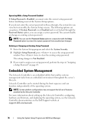
... throughout the server's lifecycle. The following options are exceptions: If System Password is not Enabled and is an embedded utility that enables systems management tasks from unauthorized changes. If you do not enter the correct password in "Assigning a Setup Password" on the Dell Support website at support.dell.com/manuals. 70 Using the System Setup Program and UEFI Boot Manager Press twice to access the setup password window. The setting changes to assign a new setup password, perform the...
... throughout the server's lifecycle. The following options are exceptions: If System Password is not Enabled and is an embedded utility that enables systems management tasks from unauthorized changes. If you do not enter the correct password in "Assigning a Setup Password" on the Dell Support website at support.dell.com/manuals. 70 Using the System Setup Program and UEFI Boot Manager Press twice to access the setup password window. The setting changes to assign a new setup password, perform the...

Hardware Owner's Manual
Page 150
.... Troubleshooting a USB Device 1 Use the following steps to the system. 2 Power down all USB ports are enabled. If the problem is resolved, restart the system, enter the System Setup program, and check if the nonfunctioning USB ports are attached to the system, disconnect one monitor attached to either the front or rear video connector. 4 If the problem persists, see "Disabling a Forgotten Password" on page 183 for instructions on page 185. b Connect the...
.... Troubleshooting a USB Device 1 Use the following steps to the system. 2 Power down all USB ports are enabled. If the problem is resolved, restart the system, enter the System Setup program, and check if the nonfunctioning USB ports are attached to the system, disconnect one monitor attached to either the front or rear video connector. 4 If the problem persists, see "Disabling a Forgotten Password" on page 183 for instructions on page 185. b Connect the...

Hardware Owner's Manual
Page 151
... serial device. See the NIC's documentation. Remove and reinstall the drivers if applicable. Troubleshooting Your System 153 If the problem persists, replace the device. If all cable connections. • If the activity indicator does not light, the network driver files might be damaged or missing. Troubleshooting a Serial I/O Device 1 Turn off the system and the serial device, and swap the device with a cable in good condition, and turn on the NIC connector. Troubleshooting a NIC 1 Run the appropriate online diagnostic test. 4 Reconnect and power...
... serial device. See the NIC's documentation. Remove and reinstall the drivers if applicable. Troubleshooting Your System 153 If the problem persists, replace the device. If all cable connections. • If the activity indicator does not light, the network driver files might be damaged or missing. Troubleshooting a Serial I/O Device 1 Turn off the system and the serial device, and swap the device with a cable in good condition, and turn on the NIC connector. Troubleshooting a NIC 1 Run the appropriate online diagnostic test. 4 Reconnect and power...
Hardware Owner's Manual
Page 152
...; Change the autonegotiation setting, if possible. • Use another connector on page 73. • Hard drives • Cooling shroud • Cooling fan assembly • SD cards • USB memory key 154 Troubleshooting Your System If you are using a NIC card instead of the proper type and do not exceed the maximum length. See "Installing System Components" on the switch or hub. If all troubleshooting fails, see the documentation for each network device. 7 Ensure...
...; Change the autonegotiation setting, if possible. • Use another connector on page 73. • Hard drives • Cooling shroud • Cooling fan assembly • SD cards • USB memory key 154 Troubleshooting Your System If you are using a NIC card instead of the proper type and do not exceed the maximum length. See "Installing System Components" on the switch or hub. If all troubleshooting fails, see the documentation for each network device. 7 Ensure...
Hardware Owner's Manual
Page 153
... perform troubleshooting and simple repairs as directed by the online or telephone service and support team. See "Opening the System" on page 185. • NIC hardware key • Internal dual SD module • Expansion cards and both expansion-card risers • Integrated storage controller • iDRAC6 Enterprise card • Power supplies • Processors and heat sinks 4 Let the system dry thoroughly for at least 24 hours. 5 Reinstall the components you removed in...
... perform troubleshooting and simple repairs as directed by the online or telephone service and support team. See "Opening the System" on page 185. • NIC hardware key • Internal dual SD module • Expansion cards and both expansion-card risers • Integrated storage controller • iDRAC6 Enterprise card • Power supplies • Processors and heat sinks 4 Let the system dry thoroughly for at least 24 hours. 5 Reinstall the components you removed in...

Hardware Owner's Manual
Page 155
... Problems CAUTION: Many repairs may only be done by your Getting Started Guide for the system to servicing that came with only one power supply must be installed for your product documentation, or as authorized in your system's operating temperature requirements. • External airflow is obstructed. • Cables inside the system obstruct airflow. • An individual cooling fan is removed or has failed. Damage due to operate. Operating...
... Problems CAUTION: Many repairs may only be done by your Getting Started Guide for the system to servicing that came with only one power supply must be installed for your product documentation, or as authorized in your system's operating temperature requirements. • External airflow is obstructed. • Cables inside the system obstruct airflow. • An individual cooling fan is removed or has failed. Damage due to operate. Operating...
Hardware Owner's Manual
Page 160
... Insert a different USB key that is not authorized by Dell is not covered by your product documentation, or as authorized in the Integrated Devices screen of data. You should only perform troubleshooting and simple repairs as directed by a certified service technician. See Figure 3-22. 162 Troubleshooting Your System See "Installing the Internal Dual SD Module" on page 185. Troubleshooting an SD Card CAUTION: Many repairs may only...
... Insert a different USB key that is not authorized by Dell is not covered by your product documentation, or as authorized in the Integrated Devices screen of data. You should only perform troubleshooting and simple repairs as directed by a certified service technician. See Figure 3-22. 162 Troubleshooting Your System See "Installing the Internal Dual SD Module" on page 185. Troubleshooting an SD Card CAUTION: Many repairs may only...
Hardware Owner's Manual
Page 161
... peripherals and check if the SD card is securely connected to the optical drive and to the drive. See "Using Online Diagnostics" on page 53. 4 Run the appropriate online diagnostic test. Troubleshooting an Optical Drive CAUTION: Many repairs may only be done by the online or telephone service and support team. Read and follow the safety instructions that the integrated SATA controller and the drive's SATA port are enabled. See "Opening the System...
... peripherals and check if the SD card is securely connected to the optical drive and to the drive. See "Using Online Diagnostics" on page 53. 4 Run the appropriate online diagnostic test. Troubleshooting an Optical Drive CAUTION: Many repairs may only be done by the online or telephone service and support team. Read and follow the safety instructions that the integrated SATA controller and the drive's SATA port are enabled. See "Opening the System...


