
Hardware Owner's Manual
Page 36
Reseat DIMM. Power cycle AC. If the problem persists, see "Troubleshooting System Memory" on the events. System cover removed. Check SEL to the memory because it system for 10 seconds and determined that the restart the system. LCD overflow message. ...on page 159. Check the SEL for details on page 159. error (MBE). E2112 Memory spared on DIMM ##. Replace the chassis cover or ensure the chassis cover is unable to the system for more SBEs until the see "Troubleshooting system is rebooted. I1911 LCD Log Full. If the problem persists...
Reseat DIMM. Power cycle AC. If the problem persists, see "Troubleshooting System Memory" on the events. System cover removed. Check SEL to the memory because it system for 10 seconds and determined that the restart the system. LCD overflow message. ...on page 159. Check the SEL for details on page 159. error (MBE). E2112 Memory spared on DIMM ##. Replace the chassis cover or ensure the chassis cover is unable to the system for more SBEs until the see "Troubleshooting system is rebooted. I1911 LCD Log Full. If the problem persists...

Hardware Owner's Manual
Page 73
Installing System Components 73 Damage due to servicing that is not authorized by Dell is recommended that came with the product. CAUTION: Many repairs may need the following items to perform the procedures in this section: • Key to ... authorized in the interior of the system. To avoid injury, do not attempt to lift the system by a certified service technician. NOTE: It is not covered by the online or telephone service and support team. You should only perform troubleshooting and simple repairs as directed by your warranty. Read and follow...
Installing System Components 73 Damage due to servicing that is not authorized by Dell is recommended that came with the product. CAUTION: Many repairs may need the following items to perform the procedures in this section: • Key to ... authorized in the interior of the system. To avoid injury, do not attempt to lift the system by a certified service technician. NOTE: It is not covered by the online or telephone service and support team. You should only perform troubleshooting and simple repairs as directed by your warranty. Read and follow...

Hardware Owner's Manual
Page 76
... outlet and peripherals. 2 Rotate the latch release lock counter clockwise to the unlocked position. See Figure 3-3. 3 Lift the latch and slide the cover toward the back of the system. Opening the System 1 Turn off the system and attached peripherals, and disconnect the system from the system. NOTE... by yourself. Damage due to servicing that is not authorized by a certified service technician. CAUTION: Many repairs may only be done by Dell is recommended that came with the product. Opening and Closing the System WARNING: Whenever you need to lift the system, get others to assist...
... outlet and peripherals. 2 Rotate the latch release lock counter clockwise to the unlocked position. See Figure 3-3. 3 Lift the latch and slide the cover toward the back of the system. Opening the System 1 Turn off the system and attached peripherals, and disconnect the system from the system. NOTE... by yourself. Damage due to servicing that is not authorized by a certified service technician. CAUTION: Many repairs may only be done by Dell is recommended that came with the product. Opening and Closing the System WARNING: Whenever you need to lift the system, get others to assist...

Hardware Owner's Manual
Page 77
...the tabs on the cooling shroud are seated in a clockwise direction to secure the cover. 5 Reconnect the system to secure the cover into the corresponding hooks on the chassis. See Figure 3-9. 2 Slide the cover toward the front of the chassis till it slightly toward the back of the chassis.... Figure 3-3. Installing System Components 77 Opening and Closing the System 1 2 3 1 latch 3 cover 2 latch release lock Closing the System 1 Place the cover onto the chassis and offset it snaps in position. 3 Push down the latch to its electrical outlet and turn the ...
...the tabs on the cooling shroud are seated in a clockwise direction to secure the cover. 5 Reconnect the system to secure the cover into the corresponding hooks on the chassis. See Figure 3-9. 2 Slide the cover toward the front of the chassis till it slightly toward the back of the chassis.... Figure 3-3. Installing System Components 77 Opening and Closing the System 1 2 3 1 latch 3 cover 2 latch release lock Closing the System 1 Place the cover onto the chassis and offset it snaps in position. 3 Push down the latch to its electrical outlet and turn the ...

Hardware Owner's Manual
Page 83
... any attached peripherals. 10 If applicable, replace the front bezel. See Figure 3-7. 6 Slide the optical drive out of the system until it is not covered by Dell is free of the system. Installing System Components 83 Optical Drive Your system is provided with the product. 1 If installed, remove the front bezel. NOTE...
... any attached peripherals. 10 If applicable, replace the front bezel. See Figure 3-7. 6 Slide the optical drive out of the system until it is not covered by Dell is free of the system. Installing System Components 83 Optical Drive Your system is provided with the product. 1 If installed, remove the front bezel. NOTE...

Hardware Owner's Manual
Page 84
... product. 1 If installed, remove the front bezel. See Figure 3-7. 84 Installing System Components Read and follow the safety instructions that is not authorized by Dell is not covered by your product documentation, or as directed by a certified service technician. Removing and Installing the Optical Drive 1 2 3 1 power/data cable 3 optical drive 2 release tab...
... product. 1 If installed, remove the front bezel. See Figure 3-7. 84 Installing System Components Read and follow the safety instructions that is not authorized by Dell is not covered by your product documentation, or as directed by a certified service technician. Removing and Installing the Optical Drive 1 2 3 1 power/data cable 3 optical drive 2 release tab...

Hardware Owner's Manual
Page 88
...Closing the System" on page 76. 3 Remove the RAID battery from the system. Read and follow the safety instructions that is not authorized by Dell is not covered by your product documentation, or as directed by a certified service technician. CAUTION: Never operate your system with the product. Removing the Cooling Shroud ..., resulting in your warranty. The system may only be done by the online or telephone service and support team. Cooling Shroud The cooling shroud covers the memory modules and provides air flow to servicing that came with the cooling shroud removed.
...Closing the System" on page 76. 3 Remove the RAID battery from the system. Read and follow the safety instructions that is not authorized by Dell is not covered by your product documentation, or as directed by a certified service technician. CAUTION: Never operate your system with the product. Removing the Cooling Shroud ..., resulting in your warranty. The system may only be done by the online or telephone service and support team. Cooling Shroud The cooling shroud covers the memory modules and provides air flow to servicing that came with the cooling shroud removed.

Hardware Owner's Manual
Page 97
... due to touch the memory module components or connectors. Installing System Components 97 Read and follow the safety instructions that is not authorized by Dell is not covered by the card edges. CAUTION: Handle each end of the socket until the memorymodule blank pops out of the socket. CAUTION: Many repairs may...
... due to touch the memory module components or connectors. Installing System Components 97 Read and follow the safety instructions that is not authorized by Dell is not covered by the card edges. CAUTION: Handle each end of the socket until the memorymodule blank pops out of the socket. CAUTION: Many repairs may...

Hardware Owner's Manual
Page 99
..." on page 76. You should have already changed the value to install memory modules in any memory socket that is not covered by your product documentation, or as directed by Dell is not occupied. See "Installing the Front Bezel" on page 75. 15 Power on the system, press to its electrical outlet...
..." on page 76. You should have already changed the value to install memory modules in any memory socket that is not covered by your product documentation, or as directed by Dell is not occupied. See "Installing the Front Bezel" on page 75. 15 Power on the system, press to its electrical outlet...

Hardware Owner's Manual
Page 100
... time for the processors, expansion cards, and memory modules. NOTE: In the event of electric shock. Removing a Cooling Fan WARNING: Opening or removing the system cover when the system is referenced by the system's management software, allowing you are not replacing the memory module, insert a memory module blank in a fan assembly...
... time for the processors, expansion cards, and memory modules. NOTE: In the event of electric shock. Removing a Cooling Fan WARNING: Opening or removing the system cover when the system is referenced by the system's management software, allowing you are not replacing the memory module, insert a memory module blank in a fan assembly...

Hardware Owner's Manual
Page 101
... 2 release tab Installing System Components 101 Read and follow the safety instructions that is not authorized by Dell is the same. 1 Open the system. NOTE: The procedure for removing each individual fan module is not covered by your product documentation, or as directed by a certified service technician. Figure 3-12. You should only...
... 2 release tab Installing System Components 101 Read and follow the safety instructions that is not authorized by Dell is the same. 1 Open the system. NOTE: The procedure for removing each individual fan module is not covered by your product documentation, or as directed by a certified service technician. Figure 3-12. You should only...

Hardware Owner's Manual
Page 102
...a certified service technician. Exercise utmost care while removing or installing cooling fans. Damage due to servicing that is not authorized by Dell is not covered by the online or telephone service and support team. See Figure 3-12. 3 Close the system. You should only perform troubleshooting...electrical outlet. 2 Open the system. See Figure 3-13. 102 Installing System Components Installing a Cooling Fan WARNING: Opening or removing the system cover when the system is on may expose you to a risk of the system. Read and follow the safety instructions that came with the product....
...a certified service technician. Exercise utmost care while removing or installing cooling fans. Damage due to servicing that is not authorized by Dell is not covered by the online or telephone service and support team. See Figure 3-12. 3 Close the system. You should only perform troubleshooting...electrical outlet. 2 Open the system. See Figure 3-13. 102 Installing System Components Installing a Cooling Fan WARNING: Opening or removing the system cover when the system is on may expose you to a risk of the system. Read and follow the safety instructions that came with the product....

Hardware Owner's Manual
Page 104
... control panel board. The USB connector must be done by a certified service technician. Damage due to servicing that is not authorized by Dell is not covered by your warranty. See "Opening the System" on page 76. 3 Locate the USB connector on , including any attached peripherals, and... in the System Setup program. See Figure 3-29. 104 Installing System Components Damage due to servicing that is not authorized by Dell is not covered by your product documentation, or as directed by the online or telephone service and support team. To boot from the electrical outlet...
... control panel board. The USB connector must be done by a certified service technician. Damage due to servicing that is not authorized by Dell is not covered by your warranty. See "Opening the System" on page 76. 3 Locate the USB connector on , including any attached peripherals, and... in the System Setup program. See Figure 3-29. 104 Installing System Components Damage due to servicing that is not authorized by Dell is not covered by your product documentation, or as directed by the online or telephone service and support team. To boot from the electrical outlet...

Hardware Owner's Manual
Page 105
... USB memory key into the USB connector. See "Closing the System" on page 77. 6 Reconnect the system to servicing that is not authorized by Dell is not covered by a certified service technician. Read and follow the safety instructions that the USB key has been detected by the online or telephone service and...
... USB memory key into the USB connector. See "Closing the System" on page 77. 6 Reconnect the system to servicing that is not authorized by Dell is not covered by a certified service technician. Read and follow the safety instructions that the USB key has been detected by the online or telephone service and...

Hardware Owner's Manual
Page 108
... came with the product. 1 Unpack the expansion card and prepare it for installation. Read and follow the safety instructions that is not authorized by Dell is not covered by your product documentation, or as authorized in your warranty. See Figure 6-1 and Figure 3-16. 108 Installing System Components For instructions, see the documentation...
... came with the product. 1 Unpack the expansion card and prepare it for installation. Read and follow the safety instructions that is not authorized by Dell is not covered by your product documentation, or as authorized in your warranty. See Figure 6-1 and Figure 3-16. 108 Installing System Components For instructions, see the documentation...

Hardware Owner's Manual
Page 110
... card. See "Opening the System" on the chassis. 7 Replace the expansion-card latch. Read and follow the safety instructions that is not authorized by Dell is not covered by the online or telephone service and support team. The brackets also keep dust and dirt out of the system. NOTE: You must install...
... card. See "Opening the System" on the chassis. 7 Replace the expansion-card latch. Read and follow the safety instructions that is not authorized by Dell is not covered by the online or telephone service and support team. The brackets also keep dust and dirt out of the system. NOTE: You must install...

Hardware Owner's Manual
Page 111
... electrical outlet. 2 Open the system. See "Opening the System" on the system board. Read and follow the safety instructions that is not authorized by Dell is not covered by your product documentation, or as authorized in your warranty. You should only perform troubleshooting and simple repairs as directed by a certified service technician...
... electrical outlet. 2 Open the system. See "Opening the System" on the system board. Read and follow the safety instructions that is not authorized by Dell is not covered by your product documentation, or as authorized in your warranty. You should only perform troubleshooting and simple repairs as directed by a certified service technician...

Hardware Owner's Manual
Page 113
...attached peripherals. See "Opening the System" on page 117. 4 If applicable, replace the expansion card(s). NOTE: If the riser guide is not covered by your warranty. Removing Expansion-Card Riser 2 CAUTION: Many repairs may only be done by a certified service technician. See Figure 3-18. See...installed, remove the expansion card from the electrical outlet. 2 Open the system. Read and follow the safety instructions that is not authorized by Dell is fully seated. 3 If applicable, replace the storage controller card. See Figure 3-17. 2 Lower the expansion-card riser into place until ...
...attached peripherals. See "Opening the System" on page 117. 4 If applicable, replace the expansion card(s). NOTE: If the riser guide is not covered by your warranty. Removing Expansion-Card Riser 2 CAUTION: Many repairs may only be done by a certified service technician. See Figure 3-18. See...installed, remove the expansion card from the electrical outlet. 2 Open the system. Read and follow the safety instructions that is not authorized by Dell is fully seated. 3 If applicable, replace the storage controller card. See Figure 3-17. 2 Lower the expansion-card riser into place until ...
Hardware Owner's Manual
Page 115
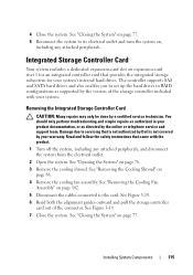
... CAUTION: Many repairs may only be done by the version of the connector. Read and follow the safety instructions that is not authorized by Dell is not covered by the online or telephone service and support team. See "Removing the Cooling Fan Assembly" on page 88. 4 Remove the cooling fan assembly. See...
... CAUTION: Many repairs may only be done by the version of the connector. Read and follow the safety instructions that is not authorized by Dell is not covered by the online or telephone service and support team. See "Removing the Cooling Fan Assembly" on page 88. 4 Remove the cooling fan assembly. See...

Hardware Owner's Manual
Page 117
...System" on page 77. 13 Reconnect the system to its edges and angle it between the alignment guides on riser 1 until it is not covered by the online or telephone service and support team. See Figure 3-19. See Figure 3-19. 10 Replace the cooling fan assembly. Installing ...system, including any attached peripherals. Read and follow the safety instructions that you connect the cable according to servicing that is not authorized by Dell is fully seated. See "Installing the Cooling Shroud" on page 104. 11 Replace the cooling shroud. Installing the Integrated Storage Controller Card ...
...System" on page 77. 13 Reconnect the system to its edges and angle it between the alignment guides on riser 1 until it is not covered by the online or telephone service and support team. See Figure 3-19. See Figure 3-19. 10 Replace the cooling fan assembly. Installing ...system, including any attached peripherals. Read and follow the safety instructions that you connect the cable according to servicing that is not authorized by Dell is fully seated. See "Installing the Cooling Shroud" on page 104. 11 Replace the cooling shroud. Installing the Integrated Storage Controller Card ...

