
Glossary
Page 1
... is located. Common Information Model describes the management information utilized by an administrator, for developing technology standards in the U.S. Dell™ Glossary NOTE: For additional information on storage terminology, visit the Storage Networking Industry Association's website at www.snia....org and click on a regular basis. American National Standards Institute. A module that includes power supplies and fans. An information pathway between the processor and RAM. ambient temperature - As a precaution, back up your system...
... is located. Common Information Model describes the management information utilized by an administrator, for developing technology standards in the U.S. Dell™ Glossary NOTE: For additional information on storage terminology, visit the Storage Networking Industry Association's website at www.snia....org and click on a regular basis. American National Standards Institute. A module that includes power supplies and fans. An information pathway between the processor and RAM. ambient temperature - As a precaution, back up your system...

Glossary
Page 2
... interference. Electrostatic discharge. Your system contains an expansion bus that allows the processor to communicate with a peripheral. An add-in card, such as the power button and power indicator. coprocessor - Dynamic Host Configuration Protocol. Dual in memory modules that allows the operating system or some specialized function to interface correctly with controllers...
... interference. Electrostatic discharge. Your system contains an expansion bus that allows the processor to communicate with a peripheral. An add-in card, such as the power button and power indicator. coprocessor - Dynamic Host Configuration Protocol. Dual in memory modules that allows the operating system or some specialized function to interface correctly with controllers...

Glossary
Page 3
...the data path and physical interface between the processor and the main memory (RAM). The ability to 1,000,000,000 bytes. Hz - Integrated Dell Remote Access Controller. IPv6 - flash memory - Front-side bus. The FSB is usually rounded to insert or install a device, typically a... chip that can be programmed and reprogrammed using a software utility. graphics mode - A keyboard is an input device, and a monitor is powered on the system board or riser board for connection of processors with networked storage devices. Gigabyte(s); 1024 megabytes or 1,073,741,824 bytes. ...
...the data path and physical interface between the processor and the main memory (RAM). The ability to 1,000,000,000 bytes. Hz - Integrated Dell Remote Access Controller. IPv6 - flash memory - Front-side bus. The FSB is usually rounded to insert or install a device, typically a... chip that can be programmed and reprogrammed using a software utility. graphics mode - A keyboard is an input device, and a monitor is powered on the system board or riser board for connection of processors with networked storage devices. Gigabyte(s); 1024 megabytes or 1,073,741,824 bytes. ...

Glossary
Page 6
... in rows and columns to run on your system. Power-on a video display. ns - Redundant information that provides electrical power to a system. You can contain multiple logical drives. A power source with multiple power outlets that is used for local-bus implementation. A... objects and accesses data and event notifications from a variety of pixels up and down. parity stripe - PDU - Power distribution unit. PowerEdge RAID controller. peripheral - CPU is an implementation-specific integer or pointer that controls the interpretation and execution of booting ...
... in rows and columns to run on your system. Power-on a video display. ns - Redundant information that provides electrical power to a system. You can contain multiple logical drives. A power source with multiple power outlets that is used for local-bus implementation. A... objects and accesses data and event notifications from a variety of pixels up and down. parity stripe - PDU - Power distribution unit. PowerEdge RAID controller. peripheral - CPU is an implementation-specific integer or pointer that controls the interpretation and execution of booting ...

Glossary
Page 8
... again. See RAM. termination - Some devices (such as the processor(s), RAM, controllers for peripherals, and various ROM chips. U-DIMM - Uninterruptible power supply. USB memory key - A standard interface that has two or more disks in the configuration software for operation. striping - system board - ...only uses a portion of a SCSI cable) must be terminated to prevent reflections and spurious signals in memory that automatically supplies power to your system's integral components, such as the last device at each processor has equal access to other hubs or switches ...
... again. See RAM. termination - Some devices (such as the processor(s), RAM, controllers for peripherals, and various ROM chips. U-DIMM - Uninterruptible power supply. USB memory key - A standard interface that has two or more disks in the configuration software for operation. striping - system board - ...only uses a portion of a SCSI cable) must be terminated to prevent reflections and spurious signals in memory that automatically supplies power to your system's integral components, such as the last device at each processor has equal access to other hubs or switches ...
Glossary
Page 46
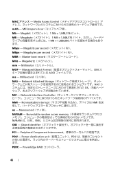
... - Milliampere-hour Mb - Megabyte 1 MB = 1,048,576 1 MB = 1,000,000 Mbps - Nanosecond NVRAM - Millimeter MOF - Megabits per second MBR - Network Attached Storage NAS OS NIC - PowerEdge RAID 46 MAC Media Access Control mAh - Network Interface Controller NMI - Power distribution unit PDU PERC - Nonmaskable interrupt NMI ns - Millisecond NAS - Megabytes per second MBps -
... - Milliampere-hour Mb - Megabyte 1 MB = 1,048,576 1 MB = 1,000,000 Mbps - Nanosecond NVRAM - Millimeter MOF - Megabits per second MBR - Network Attached Storage NAS OS NIC - PowerEdge RAID 46 MAC Media Access Control mAh - Network Interface Controller NMI - Power distribution unit PDU PERC - Nonmaskable interrupt NMI ns - Millisecond NAS - Megabytes per second MBps -
Glossary
Page 47
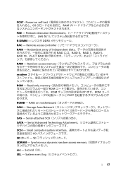
... - Random-access memory RAM readme ROM - RAID on self-test OS RAM PXE - Storage Area Network SAS - Read-only memory ROM ROM ROM POST ROMB - Power-on motherboard RAID)。 SAN - Serial-attached SCSI SCSI)。 SATA - System event log 47 Small computer system interface I/O SD SD SDRAM - Serial...
... - Random-access memory RAM readme ROM - RAID on self-test OS RAM PXE - Storage Area Network SAS - Read-only memory ROM ROM ROM POST ROMB - Power-on motherboard RAID)。 SAN - Serial-attached SCSI SCSI)。 SATA - System event log 47 Small computer system interface I/O SD SD SDRAM - Serial...

Glossary
Page 48
... current VGA - Windows Management Instrumentation。CIM ZIF - Zero insertion force 48 Volts alternating current VDC - Self-Monitoring Analysis and Reporting Technology BIOS SMP - Uninterruptible power supply USB - Watt-hour WMI - Super video graphics array VGA と SVGA TCP/IP - Volt VAC - SMART - Symmetric multiprocessing I/O OS SNMP - TCP/IP U-DIMM - Video...
... current VGA - Windows Management Instrumentation。CIM ZIF - Zero insertion force 48 Volts alternating current VDC - Self-Monitoring Analysis and Reporting Technology BIOS SMP - Uninterruptible power supply USB - Watt-hour WMI - Super video graphics array VGA と SVGA TCP/IP - Volt VAC - SMART - Symmetric multiprocessing I/O OS SNMP - TCP/IP U-DIMM - Video...
Glossary
Page 53
Dell Storage Networking Industry Association www.snia.org A Ampere AC Alternating Current ACPI Advanced Configuration and Power Interface ANSI American National Standards Institute BMC Baseboard Management Controller BTU British Thermal Unit C - 섭씨 (Celsius CA Certificate Authority CIM Common Information Model) 은 ...
Dell Storage Networking Industry Association www.snia.org A Ampere AC Alternating Current ACPI Advanced Configuration and Power Interface ANSI American National Standards Institute BMC Baseboard Management Controller BTU British Thermal Unit C - 섭씨 (Celsius CA Certificate Authority CIM Common Information Model) 은 ...
Glossary
Page 56
... NAS NIC Network Interface Controller NMI Nonmaskable Interrupt NMI ns Nanosecond NVRAM Nonvolatile Random-Access Memory NVRAM OID Object Identifier PCI Peripheral Component Interconnect PDU Power Distribution Unit PERC - PowerEdge RAID POST Power-On Self-Test POST RAM PXE Preboot eXecution Environment LAN R-DIMM DDR3 Registered DDR3 Memory Module 56
... NAS NIC Network Interface Controller NMI Nonmaskable Interrupt NMI ns Nanosecond NVRAM Nonvolatile Random-Access Memory NVRAM OID Object Identifier PCI Peripheral Component Interconnect PDU Power Distribution Unit PERC - PowerEdge RAID POST Power-On Self-Test POST RAM PXE Preboot eXecution Environment LAN R-DIMM DDR3 Registered DDR3 Memory Module 56

Glossary
Page 58
... TCP/IP Transmission Control Protocol/Internet Protocol TOE - TCP/IP TCP/IP Offload Engine U-DIMM DDR3 Unregistered(Unbuffered) DDR3 Memory Module UPS Uninterruptible Power Supply USB Universal Serial Bus USB USB USB USB V - 볼트 (Volt VAC Volt Alternating Current VDC Volt Direct Current VGA Video...;트 (Watt WH Watt-Hour WMI - Windows Management Instrumentation 은 CIM ZIF Zero Insertion Force provider CIM management station managed system) 은 Dell OpenManage™ Server Administrator x x y x z 58
... TCP/IP Transmission Control Protocol/Internet Protocol TOE - TCP/IP TCP/IP Offload Engine U-DIMM DDR3 Unregistered(Unbuffered) DDR3 Memory Module UPS Uninterruptible Power Supply USB Universal Serial Bus USB USB USB USB V - 볼트 (Volt VAC Volt Alternating Current VDC Volt Direct Current VGA Video...;트 (Watt WH Watt-Hour WMI - Windows Management Instrumentation 은 CIM ZIF Zero Insertion Force provider CIM management station managed system) 은 Dell OpenManage™ Server Administrator x x y x z 58

Information Update - Power Infrastructure Sizing
Page 1
... with circuit protection devices such as 20KW. June 2009 Systems characterized while using the power capping features enabled from Dell may result in 500W of the power supply power rating. Example: If a server power supply is assessed under a peak workload for peak power consumption. Using system power capping at 1000W and the characterization results in a significantly different...
... with circuit protection devices such as 20KW. June 2009 Systems characterized while using the power capping features enabled from Dell may result in 500W of the power supply power rating. Example: If a server power supply is assessed under a peak workload for peak power consumption. Using system power capping at 1000W and the characterization results in a significantly different...

Getting Started Guide
Page 6
Optional - Be sure to tighten the screws (if any) on the back of your system have icons indicating which cable to the monitor. 4 Getting Started With Your System Connecting the Keyboard, Mouse, and Monitor Connect the keyboard, mouse, and monitor (optional). The connectors on the monitor's cable connector. Connecting the Power Cable(s) Connect the system's power cable(s) to the system and, if a monitor is used, connect the monitor's power cable to plug into each connector.
Optional - Be sure to tighten the screws (if any) on the back of your system have icons indicating which cable to the monitor. 4 Getting Started With Your System Connecting the Keyboard, Mouse, and Monitor Connect the keyboard, mouse, and monitor (optional). The connectors on the monitor's cable connector. Connecting the Power Cable(s) Connect the system's power cable(s) to the system and, if a monitor is used, connect the monitor's power cable to plug into each connector.

Getting Started Guide
Page 7
The power indicators should light. Turning On the System Press the power button on the right bend of the power cable into a loop as an uninterrupted power supply (UPS) or a power distribution unit (PDU). Getting Started With Your System 5 Bend the system power cable into a grounded electrical outlet or a separate power source such as shown in the illustration and attach to the bracket's cable clasp. Plug the other end of the power supply handle. Securing the Power Cable(s) Attach the power cable retention bracket on the system and the monitor.
The power indicators should light. Turning On the System Press the power button on the right bend of the power cable into a loop as an uninterrupted power supply (UPS) or a power distribution unit (PDU). Getting Started With Your System 5 Bend the system power cable into a grounded electrical outlet or a separate power source such as shown in the illustration and attach to the bracket's cable clasp. Plug the other end of the power supply handle. Securing the Power Cable(s) Attach the power cable retention bracket on the system and the monitor.

Getting Started Guide
Page 13
...type Video memory Integrated Matrox G200 with iDRAC6 8 MB (shared with iDRAC application memory) Power AC power supply Wattage (per power supply) Voltage (per power supply) System heat dissipation Maximum inrush current (per power supply) Batteries System battery RAID battery (optional) 1100 W 100-240 V, 50/60 Hz...ranging 4012 BTU/Hr Under typical line conditions and over the entire system ambient operating range, the inrush current may reach 55 A per power supply for 10 ms or less CR 2032 3.0-V lithium coin cell 3.7 V lithium ion Physical Height Width Depth Weight (maximum configuration) ...
...type Video memory Integrated Matrox G200 with iDRAC6 8 MB (shared with iDRAC application memory) Power AC power supply Wattage (per power supply) Voltage (per power supply) System heat dissipation Maximum inrush current (per power supply) Batteries System battery RAID battery (optional) 1100 W 100-240 V, 50/60 Hz...ranging 4012 BTU/Hr Under typical line conditions and over the entire system ambient operating range, the inrush current may reach 55 A per power supply for 10 ms or less CR 2032 3.0-V lithium coin cell 3.7 V lithium ion Physical Height Width Depth Weight (maximum configuration) ...

Hardware Owner's Manual
Page 3
Contents 1 About Your System 11 Accessing System Features During Startup 11 Front-Panel Features and Indicators 12 LCD Panel Features 14 Home Screen 15 Setup Menu 16 View Menu 17 Hard-Drive Indicator Patterns 17 Back-Panel Features and Indicators 18 Guidelines for Connecting External Devices 20 NIC Indicator Codes 20 Power Indicator Codes 21 LCD Status Messages 22 Viewing Status Messages 23 Removing LCD Status Messages 23 System Messages 40 Warning Messages 57 Diagnostics Messages 58 Alert Messages 58 Contents 3
Contents 1 About Your System 11 Accessing System Features During Startup 11 Front-Panel Features and Indicators 12 LCD Panel Features 14 Home Screen 15 Setup Menu 16 View Menu 17 Hard-Drive Indicator Patterns 17 Back-Panel Features and Indicators 18 Guidelines for Connecting External Devices 20 NIC Indicator Codes 20 Power Indicator Codes 21 LCD Status Messages 22 Viewing Status Messages 23 Removing LCD Status Messages 23 System Messages 40 Warning Messages 57 Diagnostics Messages 58 Alert Messages 58 Contents 3

Hardware Owner's Manual
Page 4
... Settings Screen 65 Boot Settings Screen 65 Integrated Devices Screen 66 PCI IRQ Assignments Screen 67 Serial Communication Screen 67 Embedded Server Management Screen 68 Power Management Screen 69 System Security Screen 70 Exit Screen 72 Entering the UEFI Boot Manager 72 Using the UEFI Boot Manager Navigation Keys 72 UEFI...
... Settings Screen 65 Boot Settings Screen 65 Integrated Devices Screen 66 PCI IRQ Assignments Screen 67 Serial Communication Screen 67 Embedded Server Management Screen 68 Power Management Screen 69 System Security Screen 70 Exit Screen 72 Entering the UEFI Boot Manager 72 Using the UEFI Boot Manager Navigation Keys 72 UEFI...

Hardware Owner's Manual
Page 5
... a Hard-Drive Carrier 90 Installing a Hard Drive Into a Hard-Drive Carrier 91 Optical Drive 91 Removing an Optical Drive 91 Installing an Optical Drive 93 Power Supplies 94 Contents 5
... a Hard-Drive Carrier 90 Installing a Hard Drive Into a Hard-Drive Carrier 91 Optical Drive 91 Removing an Optical Drive 91 Installing an Optical Drive 93 Power Supplies 94 Contents 5

Hardware Owner's Manual
Page 6
Removing a Power Supply 94 Installing a Power Supply 95 Removing the Power Supply Blank 96 Installing the Power Supply Blank 96 Cooling Shroud 96 Removing the Cooling Shroud 96 Installing the Cooling Shroud 97 Front-Chassis Assembly 98 Sliding the Front-Chassis Assembly ...
Removing a Power Supply 94 Installing a Power Supply 95 Removing the Power Supply Blank 96 Installing the Power Supply Blank 96 Cooling Shroud 96 Removing the Cooling Shroud 96 Installing the Cooling Shroud 97 Front-Chassis Assembly 98 Sliding the Front-Chassis Assembly ...

Hardware Owner's Manual
Page 8
Removing the SAS Backplane 146 Installing the SAS Backplane 148 Power Distribution Board 149 Removing the Power Distribution Board . . . . . 149 Replacing the Power Distribution Board . . . . . 151 Control Panel Assembly 152 Removing the Control Panel Display Module 152 Installing the Control Panel Display Module 152 Removing the Control Panel ...
Removing the SAS Backplane 146 Installing the SAS Backplane 148 Power Distribution Board 149 Removing the Power Distribution Board . . . . . 149 Replacing the Power Distribution Board . . . . . 151 Control Panel Assembly 152 Removing the Control Panel Display Module 152 Installing the Control Panel Display Module 152 Removing the Control Panel ...


