
Glossary
Page 1
Dell™ Glossary NOTE: For additional information on storage terminology, visit the Storage Networking Industry Association's website at www.snia.org and click on a regular basis. Ampere(s). ACPI - American National Standards Institute. An individual code assigned to direct configuration and power management. A module that includes power supplies... The primary organization for quick data retrieval. asset tag - blade - CA - CIM - Advanced Configuration and Power Interface. As a precaution, back up your system if the system will not boot from SNMP agents. British ...
Dell™ Glossary NOTE: For additional information on storage terminology, visit the Storage Networking Industry Association's website at www.snia.org and click on a regular basis. Ampere(s). ACPI - American National Standards Institute. An individual code assigned to direct configuration and power management. A module that includes power supplies... The primary organization for quick data retrieval. asset tag - blade - CA - CIM - Advanced Configuration and Power Interface. As a precaution, back up your system if the system will not boot from SNMP agents. British ...

Glossary
Page 8
...program that has two or more disks in memory that automatically supplies power to your system's integral components, such as mice and keyboards. When such devices are video standards for the devices. Uninterruptible power supply. See memory key. 8 VGA and SVGA are connected .... Simple Network Management Protocol. Transmission Control Protocol/Internet Protocol. Super video graphics array. TOE - uplink port - A battery-powered unit that tells a system what hardware is running. An unregistered (unbuffered) DDR3 memory module. The amount of disks in the...
...program that has two or more disks in memory that automatically supplies power to your system's integral components, such as mice and keyboards. When such devices are video standards for the devices. Uninterruptible power supply. See memory key. 8 VGA and SVGA are connected .... Simple Network Management Protocol. Transmission Control Protocol/Internet Protocol. Super video graphics array. TOE - uplink port - A battery-powered unit that tells a system what hardware is running. An unregistered (unbuffered) DDR3 memory module. The amount of disks in the...

Glossary
Page 48
...。CIM ZIF - Symmetric multiprocessing I/O OS SNMP - Super video graphics array VGA と SVGA TCP/IP - Unregistered DDR3 UPS - Volt VAC - Watt-hour WMI - Uninterruptible power supply USB - Simple Network Management Protocol SVGA - SMART - Volt direct current VGA - Watt WH - Universal Serial Bus USB USB USB USB V - Video graphics array VGA と...
...。CIM ZIF - Symmetric multiprocessing I/O OS SNMP - Super video graphics array VGA と SVGA TCP/IP - Unregistered DDR3 UPS - Volt VAC - Watt-hour WMI - Uninterruptible power supply USB - Simple Network Management Protocol SVGA - SMART - Volt direct current VGA - Watt WH - Universal Serial Bus USB USB USB USB V - Video graphics array VGA と...

Glossary
Page 58
... provider CIM management station managed system) 은 Dell OpenManage™ Server Administrator x x y x z 58 SVGA Super Video Graphics Array VGA 와 SVGA TCP/IP Transmission Control Protocol/Internet Protocol TOE - TCP/IP TCP/IP Offload Engine U-DIMM DDR3 Unregistered(Unbuffered) DDR3 Memory Module UPS Uninterruptible Power Supply USB Universal Serial Bus USB USB USB...
... provider CIM management station managed system) 은 Dell OpenManage™ Server Administrator x x y x z 58 SVGA Super Video Graphics Array VGA 와 SVGA TCP/IP Transmission Control Protocol/Internet Protocol TOE - TCP/IP TCP/IP Offload Engine U-DIMM DDR3 Unregistered(Unbuffered) DDR3 Memory Module UPS Uninterruptible Power Supply USB Universal Serial Bus USB USB USB...

Information Update - Power Infrastructure Sizing
Page 1
... 1000W and the characterization results in a significantly different power consumption requirement than 50 percent. Systems characterized while using the power capping features enabled from Dell may result in 500W of Power Distribution Units (PDUs), Uninterruptible Power Supplies (UPSs), and other power infrastructure distribution equipment. Example: If a server power supply is used to understand peak power consumption for sizing the infrastructure.
... 1000W and the characterization results in a significantly different power consumption requirement than 50 percent. Systems characterized while using the power capping features enabled from Dell may result in 500W of Power Distribution Units (PDUs), Uninterruptible Power Supplies (UPSs), and other power infrastructure distribution equipment. Example: If a server power supply is used to understand peak power consumption for sizing the infrastructure.

Getting Started Guide
Page 7
The power indicators should light. Turning On the System Press the power button on the right bend of the power cable into a loop as an uninterrupted power supply (UPS) or a power distribution unit (PDU). Securing the Power Cable(s) Attach the power cable retention bracket on the system and the monitor. Getting Started With Your System 5 Plug the other end of the power supply handle. Bend the system power cable into a grounded electrical outlet or a separate power source such as shown in the illustration and attach to the bracket's cable clasp.
The power indicators should light. Turning On the System Press the power button on the right bend of the power cable into a loop as an uninterrupted power supply (UPS) or a power distribution unit (PDU). Securing the Power Cable(s) Attach the power cable retention bracket on the system and the monitor. Getting Started With Your System 5 Plug the other end of the power supply handle. Bend the system power cable into a grounded electrical outlet or a separate power source such as shown in the illustration and attach to the bracket's cable clasp.

Getting Started Guide
Page 13
... type Video memory Integrated Matrox G200 with iDRAC6 8 MB (shared with iDRAC application memory) Power AC power supply Wattage (per power supply) Voltage (per power supply) System heat dissipation Maximum inrush current (per power supply) Batteries System battery RAID battery (optional) 1100 W 100-240 V, 50/60 Hz, auto...4012 BTU/Hr Under typical line conditions and over the entire system ambient operating range, the inrush current may reach 55 A per power supply for 10 ms or less CR 2032 3.0-V lithium coin cell 3.7 V lithium ion Physical Height Width Depth Weight (maximum configuration) ...
... type Video memory Integrated Matrox G200 with iDRAC6 8 MB (shared with iDRAC application memory) Power AC power supply Wattage (per power supply) Voltage (per power supply) System heat dissipation Maximum inrush current (per power supply) Batteries System battery RAID battery (optional) 1100 W 100-240 V, 50/60 Hz, auto...4012 BTU/Hr Under typical line conditions and over the entire system ambient operating range, the inrush current may reach 55 A per power supply for 10 ms or less CR 2032 3.0-V lithium coin cell 3.7 V lithium ion Physical Height Width Depth Weight (maximum configuration) ...

Hardware Owner's Manual
Page 5
... a Hard-Drive Carrier 90 Installing a Hard Drive Into a Hard-Drive Carrier 91 Optical Drive 91 Removing an Optical Drive 91 Installing an Optical Drive 93 Power Supplies 94 Contents 5
... a Hard-Drive Carrier 90 Installing a Hard Drive Into a Hard-Drive Carrier 91 Optical Drive 91 Removing an Optical Drive 91 Installing an Optical Drive 93 Power Supplies 94 Contents 5

Hardware Owner's Manual
Page 6
Removing a Power Supply 94 Installing a Power Supply 95 Removing the Power Supply Blank 96 Installing the Power Supply Blank 96 Cooling Shroud 96 Removing the Cooling Shroud 96 Installing the Cooling Shroud 97 Front-Chassis Assembly 98 Sliding the Front-Chassis Assembly 98 ...
Removing a Power Supply 94 Installing a Power Supply 95 Removing the Power Supply Blank 96 Installing the Power Supply Blank 96 Cooling Shroud 96 Removing the Cooling Shroud 96 Installing the Cooling Shroud 97 Front-Chassis Assembly 98 Sliding the Front-Chassis Assembly 98 ...

Hardware Owner's Manual
Page 9
Troubleshooting the System Battery 166 Troubleshooting Power Supplies 167 Troubleshooting System Cooling Problems 167 Troubleshooting a Fan 168 Troubleshooting System Memory 169 Troubleshooting an Internal USB Key 171 Troubleshooting an SD Card 172 Troubleshooting ...
Troubleshooting the System Battery 166 Troubleshooting Power Supplies 167 Troubleshooting System Cooling Problems 167 Troubleshooting a Fan 168 Troubleshooting System Memory 169 Troubleshooting an Internal USB Key 171 Troubleshooting an SD Card 172 Troubleshooting ...

Hardware Owner's Manual
Page 12
... controls the DC power supply output to display an image, depending on . When the system bezel is installed, the power button is turned off the system using the power button causes the system to perform a graceful shutdown before power to the system is not accessible. During this...3 4 5 6 7 8 9 10 Item Indicator, Button, or Icon Connector 1 Power-on indicator, power button Description The power-on indicator lights when the system power is on the amount of memory installed in the system. NOTE: When powering on the system, the video monitor can take from several seconds to over two...
... controls the DC power supply output to display an image, depending on . When the system bezel is installed, the power button is turned off the system using the power button causes the system to perform a graceful shutdown before power to the system is not accessible. During this...3 4 5 6 7 8 9 10 Item Indicator, Button, or Icon Connector 1 Power-on indicator, power button Description The power-on indicator lights when the system power is on the amount of memory installed in the system. NOTE: When powering on the system, the video monitor can take from several seconds to over two...

Hardware Owner's Manual
Page 19
..., with a standard height bracket). PCI Express (Generation 2) x8 link expansion slot (24.13 cm [9.5"] length). 1100 W power supplies. Item Indicator, Button, or Icon Connector 1 PCIe slot 1 2 PCIe slot 2 3 PCIe slot 3 4 PCIe slot 4 5 PCIe slot 5 6 PCIe slot 6 7 Power supplies (2) 8 System identification button 9 System status indicator 10 System identification connector 11 Ethernet connectors (4) Description PCI Express...
..., with a standard height bracket). PCI Express (Generation 2) x8 link expansion slot (24.13 cm [9.5"] length). 1100 W power supplies. Item Indicator, Button, or Icon Connector 1 PCIe slot 1 2 PCIe slot 2 3 PCIe slot 3 4 PCIe slot 4 5 PCIe slot 5 6 PCIe slot 6 7 Power supplies (2) 8 System identification button 9 System status indicator 10 System identification connector 11 Ethernet connectors (4) Description PCI Express...

Hardware Owner's Manual
Page 21
... Mbps. When hot-adding a power supply, this indicates that matches the capacity of the other power supply. Replace the power supply that has the flashing indicator with a power supply that the power supply is connected to the network. In standby mode, a green light indicates that a valid AC source is connected to the power supply and that the power supply is not connected to a valid...
... Mbps. When hot-adding a power supply, this indicates that matches the capacity of the other power supply. Replace the power supply that has the flashing indicator with a power supply that the power supply is connected to the network. In standby mode, a green light indicates that a valid AC source is connected to the power supply and that the power supply is not connected to a valid...

Hardware Owner's Manual
Page 22
Record the code, then see "Getting Help" on the SEL and configuring system management settings, see the systems management software documentation. Power Supply Status Indicator 1 1 power supply status indicator LCD Status Messages The LCD messages consist of brief text messages that refer to boot, press the System ID button for at least 5 seconds until an error code appears on the LCD. For information on page 195. 22 About Your System NOTE: If your system fails to events recorded in the System Event Log (SEL). Figure 1-4.
Record the code, then see "Getting Help" on the SEL and configuring system management settings, see the systems management software documentation. Power Supply Status Indicator 1 1 power supply status indicator LCD Status Messages The LCD messages consist of brief text messages that refer to boot, press the System ID button for at least 5 seconds until an error code appears on the LCD. For information on page 195. 22 About Your System NOTE: If your system fails to events recorded in the System Event Log (SEL). Figure 1-4.
Hardware Owner's Manual
Page 28
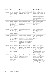
E1614 Power Supply Specified power supply # (### W) failed. See "Troubleshooting Power Supplies" on page 167. Specified power supply attached to the machine check error. power supply. The system BIOS reported a Remove AC power to the system, but lost AC power. system for the specified power supply. See "Troubleshooting Power Supplies" on page 167. communication error caused the predictive warning of an impending power supply failure. E161C Power Supply # (### W) lost its AC input...
E1614 Power Supply Specified power supply # (### W) failed. See "Troubleshooting Power Supplies" on page 167. Specified power supply attached to the machine check error. power supply. The system BIOS reported a Remove AC power to the system, but lost AC power. system for the specified power supply. See "Troubleshooting Power Supplies" on page 167. communication error caused the predictive warning of an impending power supply failure. E161C Power Supply # (### W) lost its AC input...

Hardware Owner's Manual
Page 29
.... See the Technical Specifications outlined in the Mismatch. E1631 System power The processors and memory Remove AC power to the draw exceeded throttling is no longer redundant. throttling. Contact support. If Power Supplies" on page 195. keep system for 10 seconds and threshold. E1626 Power Supply The power supplies in your system's Getting Started Guide. About Your System...
.... See the Technical Specifications outlined in the Mismatch. E1631 System power The processors and memory Remove AC power to the draw exceeded throttling is no longer redundant. throttling. Contact support. If Power Supplies" on page 195. keep system for 10 seconds and threshold. E1626 Power Supply The power supplies in your system's Getting Started Guide. About Your System...

Hardware Owner's Manual
Page 39
NOTE: For the full name of shutting down. is page 167. at support.dell.com/manuals. About Your System 39 The power supply subsystem Reseat the power supplies. If the problem persists, see the Glossary on can fail before the system is no longer fully redundant, See "Troubleshooting but at least one more supply Power Supplies" on the Dell Support website at risk of an abbreviation or acronym used in this table, see "Getting Help" on page 195. Check PSU cables. Code Text Causes Corrective Actions W1630 Power supply redundancy degraded.
NOTE: For the full name of shutting down. is page 167. at support.dell.com/manuals. About Your System 39 The power supply subsystem Reseat the power supplies. If the problem persists, see the Glossary on can fail before the system is no longer fully redundant, See "Troubleshooting but at least one more supply Power Supplies" on the Dell Support website at risk of an abbreviation or acronym used in this table, see "Getting Help" on page 195. Check PSU cables. Code Text Causes Corrective Actions W1630 Power supply redundancy degraded.

Hardware Owner's Manual
Page 41
...setting, if appropriate. Redundant memory disabled! Memory Mirroring was enabled in a configuration that node interleaving cannot be supported by the power supplies. See "Using the System Setup Program and UEFI Boot Manager" on page 100. If the system boots without node interleaving.... are not supported with this warning, then the replaced component(s) are installed in the system setup program, but without this power supply. For memory configuration information, see "Troubleshooting System Memory" on page 94. Check PSU and system configuration. Alert! Message Causes...
...setting, if appropriate. Redundant memory disabled! Memory Mirroring was enabled in a configuration that node interleaving cannot be supported by the power supplies. See "Using the System Setup Program and UEFI Boot Manager" on page 100. If the system boots without node interleaving.... are not supported with this warning, then the replaced component(s) are installed in the system setup program, but without this power supply. For memory configuration information, see "Troubleshooting System Memory" on page 94. Check PSU and system configuration. Alert! Message Causes...

Hardware Owner's Manual
Page 56
..., return the system to meet PSU wattage. See "General Memory Module Installation Guidelines" on page 94. Performance degraded. See "Power Supplies" on page 100. The recommended memory configuration is not installed. code update loaded for processor n Update the BIOS firmware. Ensure...the memory modules are not supported with reduced functionality. See "Getting Help" on page 195. System will run but with this power supply. If the system boots without this warning, then the replaced component(s) are installed in a valid configuration. The system configuration of...
..., return the system to meet PSU wattage. See "General Memory Module Installation Guidelines" on page 94. Performance degraded. See "Power Supplies" on page 100. The recommended memory configuration is not installed. code update loaded for processor n Update the BIOS firmware. Ensure...the memory modules are not supported with reduced functionality. See "Getting Help" on page 195. System will run but with this power supply. If the system boots without this warning, then the replaced component(s) are installed in a valid configuration. The system configuration of...

Hardware Owner's Manual
Page 82
Inside the System 11 10 12 1 2 3 4 9 8 7 1 cooling shroud 3 expansion-card riser 2 5 heat sinks (4) 7 hard drives (6) 9 optical drive (optional) 11 cooling fan assembly 5 6 2 power supply bays (2) 4 expansion-card riser 1 6 memory modules (32) 8 control panel 10 cooling fans (6) 12 internal dual SD module 82 Installing System Components Figure 3-1.
Inside the System 11 10 12 1 2 3 4 9 8 7 1 cooling shroud 3 expansion-card riser 2 5 heat sinks (4) 7 hard drives (6) 9 optical drive (optional) 11 cooling fan assembly 5 6 2 power supply bays (2) 4 expansion-card riser 1 6 memory modules (32) 8 control panel 10 cooling fans (6) 12 internal dual SD module 82 Installing System Components Figure 3-1.


