
Glossary
Page 1
Dell™ Glossary NOTE: For additional information on storage terminology, visit the Storage Networking Industry Association's website at www.snia.org and click on a regular basis. Alternating current. ACPI - backup - CA - AC - asset tag - BTU - bus - An information pathway between the processor and RAM. Advanced Configuration and Power... back up your system if the system will not boot from SNMP agents. blade - A module that includes power supplies and fans. BMC - Baseboard management controller. A CD, diskette, or USB memory key that is located. ...
Dell™ Glossary NOTE: For additional information on storage terminology, visit the Storage Networking Industry Association's website at www.snia.org and click on a regular basis. Alternating current. ACPI - backup - CA - AC - asset tag - BTU - bus - An information pathway between the processor and RAM. Advanced Configuration and Power... back up your system if the system will not boot from SNMP agents. blade - A module that includes power supplies and fans. BMC - Baseboard management controller. A CD, diskette, or USB memory key that is located. ...

Glossary
Page 8
Simple Network Management Protocol. A standard interface that automatically supplies power to configure your system's integral components, such as mice and keyboards. Disk striping writes data across three or more processors connected...Universal Serial Bus. SNMP - As the main circuit board, the system board usually contains most of an electrical failure. See RAM. uplink port - Uninterruptible power supply. See also guarding, mirroring, and RAID. Because the System Setup program is running. SMP - Symmetric multiprocessing. striping - The amount of a SCSI cable)...
Simple Network Management Protocol. A standard interface that automatically supplies power to configure your system's integral components, such as mice and keyboards. Disk striping writes data across three or more processors connected...Universal Serial Bus. SNMP - As the main circuit board, the system board usually contains most of an electrical failure. See RAM. uplink port - Uninterruptible power supply. See also guarding, mirroring, and RAID. Because the System Setup program is running. SMP - Symmetric multiprocessing. striping - The amount of a SCSI cable)...

Glossary
Page 48
... graphics array VGA と SVGA W - Self-Monitoring Analysis and Reporting Technology BIOS SMP - Unregistered DDR3 UPS - Volt direct current VGA - Symmetric multiprocessing I/O OS SNMP - Uninterruptible power supply USB - Volts alternating current VDC - Volt VAC - TCP/IP U-DIMM - Windows Management Instrumentation。CIM ZIF - Simple Network Management Protocol SVGA - Zero insertion force 48...
... graphics array VGA と SVGA W - Self-Monitoring Analysis and Reporting Technology BIOS SMP - Unregistered DDR3 UPS - Volt direct current VGA - Symmetric multiprocessing I/O OS SNMP - Uninterruptible power supply USB - Volts alternating current VDC - Volt VAC - TCP/IP U-DIMM - Windows Management Instrumentation。CIM ZIF - Simple Network Management Protocol SVGA - Zero insertion force 48...

Glossary
Page 58
... provider CIM management station managed system) 은 Dell OpenManage™ Server Administrator x x y x z 58 SVGA Super Video Graphics Array VGA 와 SVGA TCP/IP Transmission Control Protocol/Internet Protocol TOE - TCP/IP TCP/IP Offload Engine U-DIMM DDR3 Unregistered(Unbuffered) DDR3 Memory Module UPS Uninterruptible Power Supply USB Universal Serial Bus USB USB USB...
... provider CIM management station managed system) 은 Dell OpenManage™ Server Administrator x x y x z 58 SVGA Super Video Graphics Array VGA 와 SVGA TCP/IP Transmission Control Protocol/Internet Protocol TOE - TCP/IP TCP/IP Offload Engine U-DIMM DDR3 Unregistered(Unbuffered) DDR3 Memory Module UPS Uninterruptible Power Supply USB Universal Serial Bus USB USB USB...

User Manual
Page 7
Turning On the System Press the power button on the system and the monitor. The power indicators should light. Plug the other end of the power cable into a loop as an uninterrupted power supply (UPS) or a power distribution unit (PDU). Getting Started With Your System 5 Securing the Power Cable(s) Bend the system power cable into a grounded electrical outlet or a separate power source such as shown in the illustration and secure the cable to the bracket using the provided strap.
Turning On the System Press the power button on the system and the monitor. The power indicators should light. Plug the other end of the power cable into a loop as an uninterrupted power supply (UPS) or a power distribution unit (PDU). Getting Started With Your System 5 Securing the Power Cable(s) Bend the system power cable into a grounded electrical outlet or a separate power source such as shown in the illustration and secure the cable to the bracket using the provided strap.
User Manual
Page 13
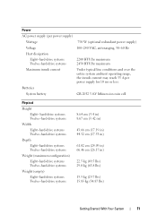
... (49.5 lbs) 29.0 kg (63.8 lbs) 13.5 kg (29.7 lbs) 15.85 kg (34.87 lbs) Getting Started With Your System 11 Power AC power supply (per power supply) Wattage 750 W (optional redundant power supply) Voltage 100-240 VAC, autoranging, 50-60 Hz Heat dissipation Eight-hard-drive systems Twelve-hard-drive systems 2200 BTU/hr maximum...
... (49.5 lbs) 29.0 kg (63.8 lbs) 13.5 kg (29.7 lbs) 15.85 kg (34.87 lbs) Getting Started With Your System 11 Power AC power supply (per power supply) Wattage 750 W (optional redundant power supply) Voltage 100-240 VAC, autoranging, 50-60 Hz Heat dissipation Eight-hard-drive systems Twelve-hard-drive systems 2200 BTU/hr maximum...

Hardware Owner's Manual
Page 6
... Optical Drive 95 Installing an Optical Drive 96 Cooling Fans 97 Removing a Cooling Fan 98 Installing a Cooling Fan 101 Power Supplies 102 Removing a Power Supply 102 Installing a Power Supply 103 Removing the Power Supply Blank 104 Installing the Power Supply Blank 104 System Memory 104 General Memory Module Installation Guidelines 105 Mode-Specific Guidelines 106 Installing Memory Modules 108 Removing...
... Optical Drive 95 Installing an Optical Drive 96 Cooling Fans 97 Removing a Cooling Fan 98 Installing a Cooling Fan 101 Power Supplies 102 Removing a Power Supply 102 Installing a Power Supply 103 Removing the Power Supply Blank 104 Installing the Power Supply Blank 104 System Memory 104 General Memory Module Installation Guidelines 105 Mode-Specific Guidelines 106 Installing Memory Modules 108 Removing...
Hardware Owner's Manual
Page 9
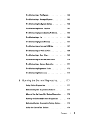
Troubleshooting a Wet System 160 Troubleshooting a Damaged System 162 Troubleshooting the System Battery 162 Troubleshooting Power Supplies 163 Troubleshooting System Cooling Problems 163 Troubleshooting a Fan 164 Troubleshooting System Memory 165 Troubleshooting an Internal USB Key 167 Troubleshooting an Optical Drive 168 Troubleshooting a ...
Troubleshooting a Wet System 160 Troubleshooting a Damaged System 162 Troubleshooting the System Battery 162 Troubleshooting Power Supplies 163 Troubleshooting System Cooling Problems 163 Troubleshooting a Fan 164 Troubleshooting System Memory 165 Troubleshooting an Internal USB Key 167 Troubleshooting an Optical Drive 168 Troubleshooting a ...

Hardware Owner's Manual
Page 12
... Indicators (Eight-Hard-Drive System) 1 2 3 456 7 8 9 10 Item Indicator, Button, Icon or Connector 1 Power-on indicator/ power button Description The power-on the system, the video monitor can take from several seconds to over 2 minutes to the system is turned off. NOTE... operating systems, turning off the system using the power button causes the system to perform a graceful shutdown before power to display an image, depending on . Front-Panel Features and Indicators Figure 1-1. The power button controls the DC power supply output to the system. When the optional system bezel...
... Indicators (Eight-Hard-Drive System) 1 2 3 456 7 8 9 10 Item Indicator, Button, Icon or Connector 1 Power-on indicator/ power button Description The power-on the system, the video monitor can take from several seconds to over 2 minutes to the system is turned off. NOTE... operating systems, turning off the system using the power button causes the system to perform a graceful shutdown before power to display an image, depending on . Front-Panel Features and Indicators Figure 1-1. The power button controls the DC power supply output to the system. When the optional system bezel...

Hardware Owner's Manual
Page 15
... of memory installed in the system. Used to the system is not accessible. Item Indicator, Button, Icon or Connector 2 LED panel 3 Power-on page 25. The power button controls the DC power supply output to do so by qualified support personnel or by the operating system's documentation. NOTE: On ACPI-compliant operating systems, turning...
... of memory installed in the system. Used to the system is not accessible. Item Indicator, Button, Icon or Connector 2 LED panel 3 Power-on page 25. The power button controls the DC power supply output to do so by qualified support personnel or by the operating system's documentation. NOTE: On ACPI-compliant operating systems, turning...

Hardware Owner's Manual
Page 22
Item Indicator, Button, or Icon Connector 9 System status indicator 10 System identification button 11 Power supply 2 (PS2) 12 Power supply 1 (PS1) Description Lights blue during normal system operation. Turns the system ID modes on the front and back panels can cause the indicator to flash ... on the front and the system status indicator on the chassis back panel light blue until one of these buttons is pushed again. 750 W redundant power supply 750 W redundant power supply 22 About Your System
Item Indicator, Button, or Icon Connector 9 System status indicator 10 System identification button 11 Power supply 2 (PS2) 12 Power supply 1 (PS1) Description Lights blue during normal system operation. Turns the system ID modes on the front and back panels can cause the indicator to flash ... on the front and the system status indicator on the chassis back panel light blue until one of these buttons is pushed again. 750 W redundant power supply 750 W redundant power supply 22 About Your System

Hardware Owner's Manual
Page 24
... 1-7. Power Supply Status Indicator 1 1 power supply status 24 About Your System Replace the power supply that has the flashing indicator with a power supply that the power supply is mismatched with the power supply. • Alternating green and amber-When hot-adding a power supply, this indicates that matches the capacity of the other power supply. When the system is on, it also indicates that the power supply is operational. Power...
... 1-7. Power Supply Status Indicator 1 1 power supply status 24 About Your System Replace the power supply that has the flashing indicator with a power supply that the power supply is mismatched with the power supply. • Alternating green and amber-When hot-adding a power supply, this indicates that matches the capacity of the other power supply. When the system is on, it also indicates that the power supply is operational. Power...

Hardware Owner's Manual
Page 31
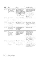
... persists, see "Troubleshooting Power Supplies" on Power Supply # (### W). Check power supply. Code E1420 E1422 E1610 E1614 E1618 E161C Text Causes Corrective Actions CPU Bus parity The system BIOS has error. parity error. Power Supply # (### W) missing. Specified power supply has failed. Check PSU. An over-temperature condition or power supply communication error has caused the predictive warning of an impending power supply failure. Power Supply # (### W) lost its...
... persists, see "Troubleshooting Power Supplies" on Power Supply # (### W). Check power supply. Code E1420 E1422 E1610 E1614 E1618 E161C Text Causes Corrective Actions CPU Bus parity The system BIOS has error. parity error. Power Supply # (### W) missing. Specified power supply has failed. Check PSU. An over-temperature condition or power supply communication error has caused the predictive warning of an impending power supply failure. Power Supply # (### W) lost its...

Hardware Owner's Manual
Page 32
...Check PSU and config. Check the SEL for the specified power error. Remove AC power to the system, reduce the hardware configuration or install higher-wattage power supplies, and then restart the system. Lost power supply redundancy. Power required > PSU wattage. Check PSU cables. The system...information and then clear the SEL. SEL. allowable range. see "Getting Help" on page 187. 32 About Your System If the remaining power supply fails, the system shuts down. If the Check PSU problem persists, cables. I /O channel Review & clear check. reported an I...
...Check PSU and config. Check the SEL for the specified power error. Remove AC power to the system, reduce the hardware configuration or install higher-wattage power supplies, and then restart the system. Lost power supply redundancy. Power required > PSU wattage. Check PSU cables. The system...information and then clear the SEL. SEL. allowable range. see "Getting Help" on page 187. 32 About Your System If the remaining power supply fails, the system shuts down. If the Check PSU problem persists, cables. I /O channel Review & clear check. reported an I...
Hardware Owner's Manual
Page 38
...spared the memory system for details on DIMM ##. Information only. The system BIOS has Remove AC power to the system, reduce the hardware configuration or install higher-wattage power supplies, and then restart the system. 38 About Your System Intrusion detected. System Event Log full. The... see "Troubleshooting System Memory" on page 137. Review & clear log. Warns predictively that the RAID battery has less than what the power supply can provide. System cover has been removed. Information only. See "Installing the RAID Battery" on page 165. Code E2112 I1910 I1912 ...
...spared the memory system for details on DIMM ##. Information only. The system BIOS has Remove AC power to the system, reduce the hardware configuration or install higher-wattage power supplies, and then restart the system. 38 About Your System Intrusion detected. System Event Log full. The... see "Troubleshooting System Memory" on page 137. Review & clear log. Warns predictively that the RAID battery has less than what the power supply can provide. System cover has been removed. Information only. See "Installing the RAID Battery" on page 165. Code E2112 I1910 I1912 ...

Hardware Owner's Manual
Page 39
Turn off the system and disconnect it can perform this table, see the Glossary at support.dell.com/manuals. when the temperature returns to the acceptable range, the message is not installed in this task remotely, but it from the ... configuration. Solving Problems Described by LCD Status Messages The code and text on , the LCD message is automatically removed when that is a failing power supply. Code Text Causes Corrective Actions W1628 Performance The system configuration degraded. but you might be able to the system, reduce the hardware configuration or install...
Turn off the system and disconnect it can perform this table, see the Glossary at support.dell.com/manuals. when the temperature returns to the acceptable range, the message is not installed in this task remotely, but it from the ... configuration. Solving Problems Described by LCD Status Messages The code and text on , the LCD message is automatically removed when that is a failing power supply. Code Text Causes Corrective Actions W1628 Performance The system configuration degraded. but you might be able to the system, reduce the hardware configuration or install...

Hardware Owner's Manual
Page 41
...Check PSU and system configuration. System fatal error during previous boot. If the system boots without this power supply. The system still runs, but without warning. See "Power Supplies" on page 105. Check other system messages for additional information for example, a memory module has...changed (for possible causes. Corrective Actions Ensure that the memory modules are not supported with High Output power supplies to use the components. If Energy Smart power supplies are installed, replace them with this warning, then the replaced component(s) are installed in a configuration ...
...Check PSU and system configuration. System fatal error during previous boot. If the system boots without this power supply. The system still runs, but without warning. See "Power Supplies" on page 105. Check other system messages for additional information for example, a memory module has...changed (for possible causes. Corrective Actions Ensure that the memory modules are not supported with High Output power supplies to use the components. If Energy Smart power supplies are installed, replace them with this warning, then the replaced component(s) are installed in a configuration ...

Hardware Owner's Manual
Page 53
... runs but with the High Output power supplies to use the components. If the system boots without this power supply. PSU mismatch. See "Power Supplies" on page 165. A High Output power supply Install two High Output and an Energy Smart power or two Energy Smart power supply are installed, replace them with reduced functionality. See "Troubleshooting Power Supplies" on page 163. System will...
... runs but with the High Output power supplies to use the components. If the system boots without this power supply. PSU mismatch. See "Power Supplies" on page 165. A High Output power supply Install two High Output and an Energy Smart power or two Energy Smart power supply are installed, replace them with reduced functionality. See "Troubleshooting Power Supplies" on page 163. System will...

Hardware Owner's Manual
Page 80
Inside the System (Eight-Hard-Drive System) 6 5 4 3 2 1 11 1 control panel board 3 power supply cooling fan 5 power supply bays (2) 7 heat sink/processor (2) 9 system cooling fans (4) 11 hard drives (8) 7 8 9 10 2 SAS backplane 4 expansion-card riser 6 cooling shroud 8 me mory modules (8) 10 optical drive (optional) 80 Installing System Components Figure 3-1.
Inside the System (Eight-Hard-Drive System) 6 5 4 3 2 1 11 1 control panel board 3 power supply cooling fan 5 power supply bays (2) 7 heat sink/processor (2) 9 system cooling fans (4) 11 hard drives (8) 7 8 9 10 2 SAS backplane 4 expansion-card riser 6 cooling shroud 8 me mory modules (8) 10 optical drive (optional) 80 Installing System Components Figure 3-1.

Hardware Owner's Manual
Page 81
Inside the System (Twelve-Hard-Drive System) 5 34 2 1 6 10 1 power supply cooling fan 3 expansion-card riser 5 cooling shroud 7 memory modules (8) 9 SAS backplane 7 8 9 2 internal hard drives (2) 4 power supply bays (2) 6 heat sink/processor (2) 8 system cooling fans (4) 10 hard drives (12) Installing System Components 81 Figure 3-2.
Inside the System (Twelve-Hard-Drive System) 5 34 2 1 6 10 1 power supply cooling fan 3 expansion-card riser 5 cooling shroud 7 memory modules (8) 9 SAS backplane 7 8 9 2 internal hard drives (2) 4 power supply bays (2) 6 heat sink/processor (2) 8 system cooling fans (4) 10 hard drives (12) Installing System Components 81 Figure 3-2.


