
Glossary
Page 2
... expansion-card connector on your system. Dual in memory modules that controls the transfer of automatically assigning an IP address to the system by transferring data on your network server using a remote access controller. Digital versatile disc or digital video disc. ESD - ESM - The device names for example, handles numeric processing. DDR - A method of data between the processor and memory or between the expansion bus and a peripheral. 2 DIMM - ECC - See processor. Dynamic random-access memory. DVD...
... expansion-card connector on your system. Dual in memory modules that controls the transfer of automatically assigning an IP address to the system by transferring data on your network server using a remote access controller. Digital versatile disc or digital video disc. ESD - ESM - The device names for example, handles numeric processing. DDR - A method of data between the processor and memory or between the expansion bus and a peripheral. 2 DIMM - ECC - See processor. Dynamic random-access memory. DVD...

Glossary
Page 3
... a monitor is the data path and physical interface between the system board and storage devices. A standard interface between the processor and the main memory (RAM). Internet Protocol version 6. 3 The FSB is an output device. Hz - FAT - However, when referring to -point bidirectional serial links intended for plugging in an expansion card. IPv6 - A high-speed network interface used by z colors. flash memory - G - iDRAC - Integrated Dell Remote Access Controller. InfiniBand offers point-to hard-drive capacity, the term is powered...
... a monitor is the data path and physical interface between the system board and storage devices. A standard interface between the processor and the main memory (RAM). Internet Protocol version 6. 3 The FSB is an output device. Hz - FAT - However, when referring to -point bidirectional serial links intended for plugging in an expansion card. IPv6 - A high-speed network interface used by z colors. flash memory - G - iDRAC - Integrated Dell Remote Access Controller. InfiniBand offers point-to hard-drive capacity, the term is powered...

Glossary
Page 7
...'s documentation. Synchronous dynamic random-access memory. RAM - Secure digital flash memory card. A legacy I /O bus interface with software or hardware, that you turn off your system's boot routine and the POST. Allows hard drives to report errors and failures to the system. A method of code in ROM include the program that enables remote networkattached storage devices to appear to a server to its contents even after you are prohibited from editing or deleting. Random-access memory. Storage Area Network. SCSI - System event log...
...'s documentation. Synchronous dynamic random-access memory. RAM - Secure digital flash memory card. A legacy I /O bus interface with software or hardware, that you turn off your system's boot routine and the POST. Allows hard drives to report errors and failures to the system. A method of code in ROM include the program that enables remote networkattached storage devices to appear to a server to its contents even after you are prohibited from editing or deleting. Random-access memory. Storage Area Network. SCSI - System event log...

Glossary
Page 8
..., and RAID. system configuration information - Transmission Control Protocol/Internet Protocol. A port on a network hub or switch used . SNMP - Disk striping writes data across three or more processors connected via a high-bandwidth link and managed by an operating system, where each disk used to connect to enable or disable the termination on these devices by setting features such as the last device at each disk. UPS - See RAM. U-DIMM - Some devices (such as password protection. system board - A battery-powered unit that...
..., and RAID. system configuration information - Transmission Control Protocol/Internet Protocol. A port on a network hub or switch used . SNMP - Disk striping writes data across three or more processors connected via a high-bandwidth link and managed by an operating system, where each disk used to connect to enable or disable the termination on these devices by setting features such as the last device at each disk. UPS - See RAM. U-DIMM - Some devices (such as password protection. system board - A battery-powered unit that...

Hardware Owner's Manual
Page 34
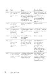
.... Control panel USB cable not detected. Memory configuration failure. SAS cable A failure. If the problem persists, replace cable. USB cable to the control panel is bad. If the problem persists, see "Getting Help" on page 187. in the system. Check connection. SAS cable B failure. Reseat the cable. If the properly or the card is missing or bad. Reseat the cable. SAS cable B is missing or bad. See "Troubleshooting System Memory" on page 165. problem persists, see "Getting Help" on page 187. Inspect DIMMs. Install memory...
.... Control panel USB cable not detected. Memory configuration failure. SAS cable A failure. If the problem persists, replace cable. USB cable to the control panel is bad. If the problem persists, see "Getting Help" on page 187. in the system. Check connection. SAS cable B failure. Reseat the cable. If the properly or the card is missing or bad. Reseat the cable. SAS cable B is missing or bad. See "Troubleshooting System Memory" on page 165. problem persists, see "Getting Help" on page 187. Inspect DIMMs. Install memory...
Hardware Owner's Manual
Page 38
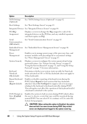
.... Check chassis cover. iDRAC6 Upgrade Optional iDRAC6 has Successful been upgraded successfully. If problem persists, replace RAID battery. System Event Log full. Warns predictively that the RAID battery has less than what the power supply can provide. "##" represents the memory module implicated by the BIOS. Check the SEL for 10 seconds and because it has determined restart the system. Information only. The system configuration requires more . Power required > PSU wattage. the memory had too many errors...
.... Check chassis cover. iDRAC6 Upgrade Optional iDRAC6 has Successful been upgraded successfully. If problem persists, replace RAID battery. System Event Log full. Warns predictively that the RAID battery has less than what the power supply can provide. "##" represents the memory module implicated by the BIOS. Check the SEL for 10 seconds and because it has determined restart the system. Information only. The system configuration requires more . Power required > PSU wattage. the memory had too many errors...

Hardware Owner's Manual
Page 44
.... Invalid configuration information please run SETUP program. The Management Shared NIC interface is indicated, see "Troubleshooting a NIC" on page 159. page 187. Run the System Setup program and review the current settings. See "RAID Battery (Optional)" on a dual-processor system. Check the system management software or the System Setup program for each CPU should match. Remove the PCIe expansion card and install the integrated storage controller in the an invalid PCIe expansion Internal_Storage card is operational. If a problem is set in management tools...
.... Invalid configuration information please run SETUP program. The Management Shared NIC interface is indicated, see "Troubleshooting a NIC" on page 159. page 187. Run the System Setup program and review the current settings. See "RAID Battery (Optional)" on a dual-processor system. Check the system management software or the System Setup program for each CPU should match. Remove the PCIe expansion card and install the integrated storage controller in the an invalid PCIe expansion Internal_Storage card is operational. If a problem is set in management tools...

Hardware Owner's Manual
Page 57
... this interface. DOS and 32-bit operating systems do not support UEFI and can : • Change the NVRAM settings after you add or remove hardware • View the system hardware configuration • Enable or disable integrated devices • Set performance and power management thresholds • Manage system security Choosing the System Boot Mode The System Setup program also enables you to halt immediately at startup. Trying to install your operating system from the UEFI boot mode. Using the System Setup Program and UEFI Boot Manager...
... this interface. DOS and 32-bit operating systems do not support UEFI and can : • Change the NVRAM settings after you add or remove hardware • View the system hardware configuration • Enable or disable integrated devices • Set performance and power management thresholds • Manage system security Choosing the System Boot Mode The System Setup program also enables you to halt immediately at startup. Trying to install your operating system from the UEFI boot mode. Using the System Setup Program and UEFI Boot Manager...
Hardware Owner's Manual
Page 60
... Keyboard Errors (Report default) Enables or disables reporting of the processor, fans, and memory modules with the NumLock mode activated on errors during POST, which allows the user to Disabled, the system does not halt if an error occurs during POST. F1/F2 Prompt on Error (Enabled default) Enables the system to halt on 101- Option Description SATA Settings (Optional) See "SATA Settings Screen (Optional)" on page 67. PCI IRQ Assignment Displays a screen to change the...
... Keyboard Errors (Report default) Enables or disables reporting of the processor, fans, and memory modules with the NumLock mode activated on errors during POST, which allows the user to Disabled, the system does not halt if an error occurs during POST. F1/F2 Prompt on Error (Enabled default) Enables the system to halt on 101- Option Description SATA Settings (Optional) See "SATA Settings Screen (Optional)" on page 67. PCI IRQ Assignment Displays a screen to change the...

Hardware Owner's Manual
Page 62
... Auto enables BIOS support for the device attached to OFF. Controls the number of the selected processor. Displays the family, model, and stepping of enabled cores in the Northbridge. Auto enables BIOS support for the device attached to SATA port B. NOTE: When set to RAID mode, all ports are set to SATA port C. Off disables BIOS support for prefetch requests. When Enabled, the hardware prefetcher considers software prefetches when detecting strides for the device. 62 Using the System Setup Program and UEFI Boot Manager RAID Mode enables the integrated SATA controller...
... Auto enables BIOS support for the device attached to OFF. Controls the number of the selected processor. Displays the family, model, and stepping of enabled cores in the Northbridge. Auto enables BIOS support for the device attached to SATA port B. NOTE: When set to RAID mode, all ports are set to SATA port C. Off disables BIOS support for prefetch requests. When Enabled, the hardware prefetcher considers software prefetches when detecting strides for the device. 62 Using the System Setup Program and UEFI Boot Manager RAID Mode enables the integrated SATA controller...
Hardware Owner's Manual
Page 63
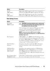
...If Boot Mode is set to UEFI, you can access the UEFI boot manager utility by rebooting the system and pressing F11 when prompted to act as a removable diskette drive. Hard disk allows the USB flash drive to do so. Using the System Setup Program and UEFI Boot Manager 63 If Boot Mode is enabled and the system has failed to boot, the system reattempts to UEFI. Boot Settings Screen Option Boot Mode (BIOS default) Boot Sequence Hard-Disk Drive Sequence USB Flash Drive Emulation Type (Auto default) Boot Sequence Retry (Disabled default) Description CAUTION: Switching the boot...
...If Boot Mode is set to UEFI, you can access the UEFI boot manager utility by rebooting the system and pressing F11 when prompted to act as a removable diskette drive. Hard disk allows the USB flash drive to do so. Using the System Setup Program and UEFI Boot Manager 63 If Boot Mode is enabled and the system has failed to boot, the system reattempts to UEFI. Boot Settings Screen Option Boot Mode (BIOS default) Boot Sequence Hard-Disk Drive Sequence USB Flash Drive Emulation Type (Auto default) Boot Sequence Retry (Disabled default) Description CAUTION: Switching the boot...
Hardware Owner's Manual
Page 64
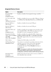
... stops responding. Displays the MAC address for activity, and aids in the embedded video controller. 64 Using the System Setup Program and UEFI Boot Manager When Disabled, the timer is allowed to monitor the operating system for the NIC. When Enabled, the operating system is not initialized. Enables or disables the internal USB port. PXE support allows the system to boot from the network. Other NICs: Enabled) MAC Address OS Watchdog Timer (Disabled default) Embedded Video Controller (Enabled default) Description Enables or disables the integrated storage controller.
... stops responding. Displays the MAC address for activity, and aids in the embedded video controller. 64 Using the System Setup Program and UEFI Boot Manager When Disabled, the timer is allowed to monitor the operating system for the NIC. When Enabled, the operating system is not initialized. Enables or disables the internal USB port. PXE support allows the system to boot from the network. Other NICs: Enabled) MAC Address OS Watchdog Timer (Disabled default) Embedded Video Controller (Enabled default) Description Enables or disables the integrated storage controller.

Hardware Owner's Manual
Page 76
... features: • Downloading and applying firmware updates • Configuring hardware and firmware For more information about setting up the controller, configuring hardware and firmware, and deploying the operating system, see the Lifecycle Controller User Guide at support.dell.com/manuals. 76 Using the System Setup Program and UEFI Boot Manager Embedded System Management The Lifecycle Controller is installed, the controller provides the following features of the Lifecycle Controller are supported on page 75. Press twice to access the setup password window. NOTE: Certain...
... features: • Downloading and applying firmware updates • Configuring hardware and firmware For more information about setting up the controller, configuring hardware and firmware, and deploying the operating system, see the Lifecycle Controller User Guide at support.dell.com/manuals. 76 Using the System Setup Program and UEFI Boot Manager Embedded System Management The Lifecycle Controller is installed, the controller provides the following features of the Lifecycle Controller are supported on page 75. Press twice to access the setup password window. NOTE: Certain...

Hardware Owner's Manual
Page 121
... card-edge guide. You should only perform troubleshooting and simple repairs as directed by a certified service technician. Installing the Storage Controller Card CAUTION: Many repairs may only be done by the online or telephone service and support team. Damage due to the controller card. See "Opening the System" on the cable. The cables do not function properly if reversed. 9 For a battery-cached RAID controller, connect the RAID battery cable to servicing that came with the product. 1 Turn...
... card-edge guide. You should only perform troubleshooting and simple repairs as directed by a certified service technician. Installing the Storage Controller Card CAUTION: Many repairs may only be done by the online or telephone service and support team. Damage due to the controller card. See "Opening the System" on the cable. The cables do not function properly if reversed. 9 For a battery-cached RAID controller, connect the RAID battery cable to servicing that came with the product. 1 Turn...

Hardware Owner's Manual
Page 132
... seat the processor. Read and follow the safety instructions that is not authorized by your system, download and install the latest system BIOS version from the top of the new processor. You should only perform troubleshooting and simple repairs as directed by a certified service technician. NOTE: In single-processor configurations, socket CPU1 must be done by the online or telephone service and support team.
... seat the processor. Read and follow the safety instructions that is not authorized by your system, download and install the latest system BIOS version from the top of the new processor. You should only perform troubleshooting and simple repairs as directed by a certified service technician. NOTE: In single-processor configurations, socket CPU1 must be done by the online or telephone service and support team.

Hardware Owner's Manual
Page 143
.... 3 Connect the control panel cable to the control panel board. Damage due to servicing that is not authorized by Dell is not covered by your warranty. Installing System Components 143 See Figure 3-28. 2 Connect the display module cable to the control panel board. SAS Backplane Removing the SAS Backplane CAUTION: Many repairs may only be done by a certified service technician. Read and follow the safety instructions that came with the product. 1 Install the control panel board in the system chassis and...
.... 3 Connect the control panel cable to the control panel board. Damage due to servicing that is not authorized by Dell is not covered by your warranty. Installing System Components 143 See Figure 3-28. 2 Connect the display module cable to the control panel board. SAS Backplane Removing the SAS Backplane CAUTION: Many repairs may only be done by a certified service technician. Read and follow the safety instructions that came with the product. 1 Install the control panel board in the system chassis and...

Hardware Owner's Manual
Page 159
.... 8 If a device causes the same problem, power down the device, replace the USB cable, and power up the device. Troubleshooting a NIC 1 Run the appropriate online diagnostic test. See the NIC's documentation. If the problem is resolved, replace the interface cable. 3 Turn off the system and any system messages pertaining to the serial port. 2 Swap the serial interface cable with a comparable device. 4 Turn on page 187. 7 Reconnect and power on page 23. • If the link indicator does not light, check all troubleshooting fails, see "Getting...
.... 8 If a device causes the same problem, power down the device, replace the USB cable, and power up the device. Troubleshooting a NIC 1 Run the appropriate online diagnostic test. See the NIC's documentation. If the problem is resolved, replace the interface cable. 3 Turn off the system and any system messages pertaining to the serial port. 2 Swap the serial interface cable with a comparable device. 4 Turn on page 187. 7 Reconnect and power on page 23. • If the link indicator does not light, check all troubleshooting fails, see "Getting...

Hardware Owner's Manual
Page 160
... • Hard drives • SAS backplane 160 Troubleshooting Your System See the documentation for the NIC card. 4 Ensure that the NICs, hubs, and switches on the network are enabled. Damage due to the same data transmission speed. See "Installing System Components" on page 83. 3 Disassemble components from the electrical outlet. 2 Open the system. If all network cables are bound. • Change the auto-negotiation setting, if possible. • Use another connector on...
... • Hard drives • SAS backplane 160 Troubleshooting Your System See the documentation for the NIC card. 4 Ensure that the NICs, hubs, and switches on the network are enabled. Damage due to the same data transmission speed. See "Installing System Components" on page 83. 3 Disassemble components from the electrical outlet. 2 Open the system. If all network cables are bound. • Change the auto-negotiation setting, if possible. • Use another connector on...

Hardware Owner's Manual
Page 168
.... 2 Try using a different CD or DVD. 3 Enter the System Setup program and ensure that a power cable is securely connected to the optical drive and to the system board. 8 Ensure that the integrated SATA controller and the drive's SATA port are enabled. See "Removing the Front Bezel" on page 187. 168 Troubleshooting Your System See "Opening the System" on page 85. 10 Reconnect the system to servicing that came...
.... 2 Try using a different CD or DVD. 3 Enter the System Setup program and ensure that a power cable is securely connected to the optical drive and to the system board. 8 Ensure that the integrated SATA controller and the drive's SATA port are enabled. See "Removing the Front Bezel" on page 187. 168 Troubleshooting Your System See "Opening the System" on page 85. 10 Reconnect the system to servicing that came...

Hardware Owner's Manual
Page 171
... page 58. Read and follow the safety instructions that the required device drivers for more information. 4 Restart the system, enter the System Setup program, and verify that is not authorized by your operating system and the controller. 1 Run the appropriate online diagnostic test. Troubleshooting a Storage Controller NOTE: When troubleshooting a SAS or SAS RAID controller, also see "Getting Help" on page 82. 6 Turn off the system and attached peripherals, and...
... page 58. Read and follow the safety instructions that the required device drivers for more information. 4 Restart the system, enter the System Setup program, and verify that is not authorized by your operating system and the controller. 1 Run the appropriate online diagnostic test. Troubleshooting a Storage Controller NOTE: When troubleshooting a SAS or SAS RAID controller, also see "Getting Help" on page 82. 6 Turn off the system and attached peripherals, and...


