
Glossary
Page 2
... tests for the serial ports on your system. driver - ERA - expansion card - A chip or expansion card that contains indicators and controls, such as the power button and power indicator. DDR - diagnostics - A comprehensive set of DRAM chips. A method of a clock cycle. Embedded remote access. ESD - Embedded server management. Your system contains an...
... tests for the serial ports on your system. driver - ERA - expansion card - A chip or expansion card that contains indicators and controls, such as the power button and power indicator. DDR - diagnostics - A comprehensive set of DRAM chips. A method of a clock cycle. Embedded remote access. ESD - Embedded server management. Your system contains an...

Getting Started Guide
Page 7
The power indicators should light. Getting Started With Your System 5 Plug the other end of the power cable into a loop as an uninterrupted power supply (UPS) or a power distribution unit (PDU). Turning On the System Press the power button on the system and the monitor. Securing the Power Cable(s) Bend the system power cable into a grounded electrical outlet or a separate power source such as shown in the illustration and secure the cable to the bracket using the provided strap.
The power indicators should light. Getting Started With Your System 5 Plug the other end of the power cable into a loop as an uninterrupted power supply (UPS) or a power distribution unit (PDU). Turning On the System Press the power button on the system and the monitor. Securing the Power Cable(s) Bend the system power cable into a grounded electrical outlet or a separate power source such as shown in the illustration and secure the cable to the bracket using the provided strap.

Hardware Owner's Manual
Page 14
... the system is on. NOTE: On ACPI-compliant operating systems, turning off . NOTE: To force an ungraceful shutdown, press and hold the power button for 5 seconds. 14 About Your System NOTE: When powering on the amount of memory installed in the system. When the optional system bezel is ...installed, the power button is not accessible. The power button controls the DC power supply output to display an image, depending on the system, the video monitor can take from several ...
... the system is on. NOTE: On ACPI-compliant operating systems, turning off . NOTE: To force an ungraceful shutdown, press and hold the power button for 5 seconds. 14 About Your System NOTE: When powering on the amount of memory installed in the system. When the optional system bezel is ...installed, the power button is not accessible. The power button controls the DC power supply output to display an image, depending on the system, the video monitor can take from several ...
Hardware Owner's Manual
Page 15
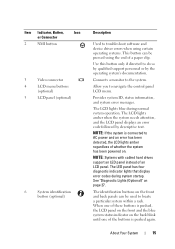
...LED panel instead of an LCD panel. Use this button only if directed to do so by qualified support personnel or by descriptive text. The identification buttons on the back blink until one of the buttons is pushed, the LCD panel on the front ... a particular system within a rack. When one of these buttons is pushed again. About Your System 15 Item Indicator, Button, Icon or Connector 2 NMI button 3 Video connector 4 LCD menu buttons (optional) 5 LCD panel (optional) 6 System identification button (optional) Description Used to troubleshoot software and device driver errors...
...LED panel instead of an LCD panel. Use this button only if directed to do so by qualified support personnel or by descriptive text. The identification buttons on the back blink until one of the buttons is pushed, the LCD panel on the front ... a particular system within a rack. When one of these buttons is pushed again. About Your System 15 Item Indicator, Button, Icon or Connector 2 NMI button 3 Video connector 4 LCD menu buttons (optional) 5 LCD panel (optional) 6 System identification button (optional) Description Used to troubleshoot software and device driver errors...

Hardware Owner's Manual
Page 16
...Enterprise card MAC address. Front-Panel Features and Indicators (Twelve-Hard-Drive System) 2 34 5 1 6 78 Item Indicator, Button, Icon or Connector 1 LED panel Description The LED panel has four diagnostic indicator lights that display error codes during system startup. Item Indicator..., Button, Icon or Connector 7 USB connectors (2) 8 Hard drives Four-hard-drive systems Eight-hard-drive systems 9 System identification panel...
...Enterprise card MAC address. Front-Panel Features and Indicators (Twelve-Hard-Drive System) 2 34 5 1 6 78 Item Indicator, Button, Icon or Connector 1 LED panel Description The LED panel has four diagnostic indicator lights that display error codes during system startup. Item Indicator..., Button, Icon or Connector 7 USB connectors (2) 8 Hard drives Four-hard-drive systems Eight-hard-drive systems 9 System identification panel...
Hardware Owner's Manual
Page 17
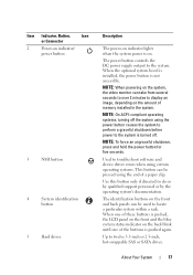
... operating system's documentation. Used to troubleshoot software and device driver errors when using certain operating systems. This button can be pressed using the power button causes the system to perform a graceful shutdown before power to twelve 3.5-inch or 2.5-inch, hot-swappable ...SAS or SATA drives. The identification buttons on the amount of memory installed in the system. Up to the system is turned off. Item Indicator, Button, Icon or Connector 2 Power-on indicator/ power button 3 NMI button 4 System identification button 5 Hard drives Description The power-on...
... operating system's documentation. Used to troubleshoot software and device driver errors when using certain operating systems. This button can be pressed using the power button causes the system to perform a graceful shutdown before power to twelve 3.5-inch or 2.5-inch, hot-swappable ...SAS or SATA drives. The identification buttons on the amount of memory installed in the system. Up to the system is turned off. Item Indicator, Button, Icon or Connector 2 Power-on indicator/ power button 3 NMI button 4 System identification button 5 Hard drives Description The power-on...
Hardware Owner's Manual
Page 18
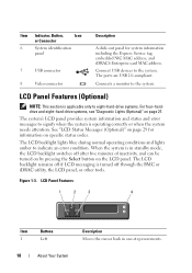
...attention. When the system is turned off after five minutes of inactivity, and can be turned on by pressing the Select button on the LCD panel. Figure 1-3. Connect USB devices to the system. The system's LCD panel provides system information and status...to eight-hard-drive systems. For four-harddrive and eight-hard-drive systems, see "Diagnostic Lights (Optional)" on page 27. Item Indicator, Button, Icon or Connector 6 System identification panel 7 USB connector 8 Video connector Description A slide-out panel for information on specific status codes. LCD Panel...
...attention. When the system is turned off after five minutes of inactivity, and can be turned on by pressing the Select button on the LCD panel. Figure 1-3. Connect USB devices to the system. The system's LCD panel provides system information and status...to eight-hard-drive systems. For four-harddrive and eight-hard-drive systems, see "Diagnostic Lights (Optional)" on page 27. Item Indicator, Button, Icon or Connector 6 System identification panel 7 USB connector 8 Video connector Description A slide-out panel for information on specific status codes. LCD Panel...
Hardware Owner's Manual
Page 19
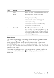
...mode on and off. Press quickly to toggle the system ID on and off after 5 minutes of the three navigation buttons (Select, Left, or Right) to enter BIOS Progress mode. Item Buttons 2 Select 3 Right 4 System ID Description Selects the menu item highlighted by the cursor. Press one -step increments....Moves the cursor forward in standby mode, the LCD backlight turns off . This screen is displayed during POST, press and hold the system ID button for more than 5 seconds to view the Home screen. When the system is displayed, and then select the Home icon. About Your System ...
...mode on and off. Press quickly to toggle the system ID on and off after 5 minutes of the three navigation buttons (Select, Left, or Right) to enter BIOS Progress mode. Item Buttons 2 Select 3 Right 4 System ID Description Selects the menu item highlighted by the cursor. Press one -step increments....Moves the cursor forward in standby mode, the LCD backlight turns off . This screen is displayed during POST, press and hold the system ID button for more than 5 seconds to view the Home screen. When the system is displayed, and then select the Home icon. About Your System ...

Hardware Owner's Manual
Page 23
.... Embedded 10/100/1000 NIC connectors. About Your System 23 Connect USB devices to the system. Connects two PCI Express Generation 2 expansion cards. Item Indicator, Button, or Icon Connector 1 Serial connector 2 Video connector 3 iDRAC6 Enterprise port (optional) 4 VFlash media slot (optional) 5 USB connectors (2) 6 Ethernet connectors (2) 7 PCIe expansion card slots using riser...
.... Embedded 10/100/1000 NIC connectors. About Your System 23 Connect USB devices to the system. Connects two PCI Express Generation 2 expansion cards. Item Indicator, Button, or Icon Connector 1 Serial connector 2 Video connector 3 iDRAC6 Enterprise port (optional) 4 VFlash media slot (optional) 5 USB connectors (2) 6 Ethernet connectors (2) 7 PCIe expansion card slots using riser...

Hardware Owner's Manual
Page 24
... particular system. Lights amber when the system needs attention due to locate a particular system within a rack. The identification buttons on and off. When one of the buttons is pushed, the LCD panel on the front and the system status indicator on the front and back of 480 W.... 24 About Your System Item Indicator, Button, or Icon Connector 9 System status indicator 10 System identification button 11 Power supply 2 (PS2) 12 Power supply 1 (PS1) Description Lights blue during normal system operation. Both...
... particular system. Lights amber when the system needs attention due to locate a particular system within a rack. The identification buttons on and off. When one of the buttons is pushed, the LCD panel on the front and the system status indicator on the front and back of 480 W.... 24 About Your System Item Indicator, Button, or Icon Connector 9 System status indicator 10 System identification button 11 Power supply 2 (PS2) 12 Power supply 1 (PS1) Description Lights blue during normal system operation. Both...
Hardware Owner's Manual
Page 27
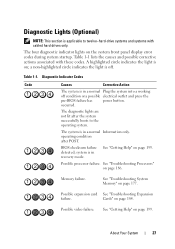
... 186. Diagnostic Indicator Codes Code Causes Corrective Action The system is off condition or a possible electrical outlet and press the pre-BIOS failure has power button. occurred. system is on; About Your System 27 A highlighted circle indicates the light is in a normal Information only. BIOS checksum failure detected; See "Troubleshooting System...
... 186. Diagnostic Indicator Codes Code Causes Corrective Action The system is off condition or a possible electrical outlet and press the pre-BIOS failure has power button. occurred. system is on; About Your System 27 A highlighted circle indicates the light is in a normal Information only. BIOS checksum failure detected; See "Troubleshooting System...
Hardware Owner's Manual
Page 29
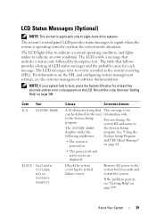
... on the SEL and configuring system management settings, see "Getting Help" on page 199. NOTE: If your system fails to boot, press the System ID button for 10 seconds and restart the system. You can be defined by descriptive text. About Your System 29 LCD Status Messages (Optional) NOTE: This section...
... on the SEL and configuring system management settings, see "Getting Help" on page 199. NOTE: If your system fails to boot, press the System ID button for 10 seconds and restart the system. You can be defined by descriptive text. About Your System 29 LCD Status Messages (Optional) NOTE: This section...

Hardware Owner's Manual
Page 48
Power down and restart the system from the power button, and then enter the System Setup program to change settings. The system runs but with the specified memory module disabled. Memory Initialization Warning: Memory size ...
Power down and restart the system from the power button, and then enter the System Setup program to change settings. The system runs but with the specified memory module disabled. Memory Initialization Warning: Memory size ...

Hardware Owner's Manual
Page 73
... returns to 240 seconds for BMC), or User Defined. Off allows the system to exit the System Setup program; When Disabled, the button can turn on system power. Enables or disables the NMI feature. Options are Immediate (no delay), Random (between 30 to 240 seconds...8226; Discard Changes and Exit • Return to do so by qualified support personnel or by the operating system's documentation. Pressing this button halts the operating system and displays a diagnostic screen. On an ACPI-compliant operating system, the system performs an orderly shutdown before power is...
... returns to 240 seconds for BMC), or User Defined. Off allows the system to exit the System Setup program; When Disabled, the button can turn on system power. Enables or disables the NMI feature. Options are Immediate (no delay), Random (between 30 to 240 seconds...8226; Discard Changes and Exit • Return to do so by qualified support personnel or by the operating system's documentation. Pressing this button halts the operating system and displays a diagnostic screen. On an ACPI-compliant operating system, the system performs an orderly shutdown before power is...

Hardware Owner's Manual
Page 78
... to be shut down and restart the system, the error message continues to protect your password. Even after you shut down manually using the power button. Disabling the System Password If the system password is already set, you to enter and verify the password. The system prompts you are different, the...
... to be shut down and restart the system, the error message continues to protect your password. Even after you shut down manually using the power button. Disabling the System Password If the system password is already set, you to enter and verify the password. The system prompts you are different, the...

Hardware Owner's Manual
Page 86
Removing and Replacing the Front Bezel 3 2 1 1 release latch 3 bezel 4 2 keylock 4 hinge tab 86 Installing System Components Figure 3-3. Front Bezel (Optional) A lock on the bezel restricts access to the key lock. 3 Rotate the left end of the bezel away from the front panel. 4 Unhook the right end of the bezel and pull the bezel away from the system. Removing the Front Bezel 1 Using the system key, unlock the bezel. 2 Lift the release latch next to the power button, optical drive, and hard drive(s). The LCD panel and navigation buttons are accessible through the front bezel.
Removing and Replacing the Front Bezel 3 2 1 1 release latch 3 bezel 4 2 keylock 4 hinge tab 86 Installing System Components Figure 3-3. Front Bezel (Optional) A lock on the bezel restricts access to the key lock. 3 Rotate the left end of the bezel away from the front panel. 4 Unhook the right end of the bezel and pull the bezel away from the system. Removing the Front Bezel 1 Using the system key, unlock the bezel. 2 Lift the release latch next to the power button, optical drive, and hard drive(s). The LCD panel and navigation buttons are accessible through the front bezel.

Hardware Owner's Manual
Page 92
.... 92 Installing System Components See "Hard-Drive Indicator Patterns" on page 86. 2 Using the RAID management software, prepare the drive for removal. 3 Press the release button and open the drive carrier release handle to release the drive. See Figure 3-8. 4 Slide the hard drive out of the drive bay. 5 Insert a drive blank...
.... 92 Installing System Components See "Hard-Drive Indicator Patterns" on page 86. 2 Using the RAID management software, prepare the drive for removal. 3 Press the release button and open the drive carrier release handle to release the drive. See Figure 3-8. 4 Slide the hard drive out of the drive bay. 5 Insert a drive blank...

Hardware Owner's Manual
Page 93
... unusable. Figure 3-8. CAUTION: When installing a hard drive, ensure that your operating system supports hot-swap drive installation. Removing and Installing a Hot-Swap Hard Drive 1 2 1 release button 2 hard-drive carrier handle Installing a Hot-Swap Hard Drive CAUTION: Use only hard drives that have been tested and approved for use with the operating...
... unusable. Figure 3-8. CAUTION: When installing a hard drive, ensure that your operating system supports hot-swap drive installation. Removing and Installing a Hot-Swap Hard Drive 1 2 1 release button 2 hard-drive carrier handle Installing a Hot-Swap Hard Drive CAUTION: Use only hard drives that have been tested and approved for use with the operating...

Hardware Owner's Manual
Page 201
... instructions for security or tracking purposes. blade - Baseboard management controller. British thermal unit. C - A fast storage area that contains indicators and controls, such as the power button and power indicator. COMn - The part of the system that keeps a copy of a system. Glossary 201 AC - ACPI - BTU - Your system contains an expansion bus...
... instructions for security or tracking purposes. blade - Baseboard management controller. British thermal unit. C - A fast storage area that contains indicators and controls, such as the power button and power indicator. COMn - The part of the system that keeps a copy of a system. Glossary 201 AC - ACPI - BTU - Your system contains an expansion bus...


