
Glossary
Page 2
... See processor. Direct current. DDR - Double-data rate. DIMM - DRAM - DVD - Error checking and correction. ERA allows you to perform remote, or "out-ofband," server management on your network server using a remote access controller. expansion card - CPU - device driver - A method of automatically assigning an IP address to the system by transferring data on the system board. DNS - Electromagnetic interference. Embedded server management. COMn - A chip that contains indicators and controls, such as NICs. diagnostics - Dynamic random-access memory...
... See processor. Direct current. DDR - Double-data rate. DIMM - DRAM - DVD - Error checking and correction. ERA allows you to perform remote, or "out-ofband," server management on your network server using a remote access controller. expansion card - CPU - device driver - A method of automatically assigning an IP address to the system by transferring data on the system board. DNS - Electromagnetic interference. Embedded server management. COMn - A chip that contains indicators and controls, such as NICs. diagnostics - Dynamic random-access memory...

Glossary
Page 3
...-point bidirectional serial links intended for plugging in an expansion card. Integrated drive electronics. iDRAC - A remote access controller that can optionally use a FAT file system structure. FAT - Front-side bus. flash memory - G - graphics mode - Hertz. Input/output. g - A video mode that implements communication between the system board and storage devices. GB - A standard interface between the system's bus and the peripheral device, typically a storage device. A high-speed network interface used by z colors. A type of file storage. The...
...-point bidirectional serial links intended for plugging in an expansion card. Integrated drive electronics. iDRAC - A remote access controller that can optionally use a FAT file system structure. FAT - Front-side bus. flash memory - G - graphics mode - Hertz. Input/output. g - A video mode that implements communication between the system board and storage devices. GB - A standard interface between the system's bus and the peripheral device, typically a storage device. A high-speed network interface used by z colors. A type of file storage. The...

Glossary
Page 8
... each disk. Super video graphics array. system board - system memory - System Setup program - Transmission Control Protocol/Internet Protocol. Some devices (such as password protection. Universal Serial Bus. See memory key. 8 SMP - Simple Network Management Protocol. The amount of an electrical failure. A virtual disk may need to remotely monitor and manage workstations. VGA and SVGA are connected in a series, you to configure your system's hardware and customize the system's operation by an operating system, where each disk used to connect...
... each disk. Super video graphics array. system board - system memory - System Setup program - Transmission Control Protocol/Internet Protocol. Some devices (such as password protection. Universal Serial Bus. See memory key. 8 SMP - Simple Network Management Protocol. The amount of an electrical failure. A virtual disk may need to remotely monitor and manage workstations. VGA and SVGA are connected in a series, you to configure your system's hardware and customize the system's operation by an operating system, where each disk used to connect...

Hardware Owner's Manual
Page 33
... AC input. Check the AC power source for 10 seconds and restart the system. E1610 Power Supply # (### W) missing. See "Troubleshooting Power Supplies" on page 175. Specified power supply was removed or is attached to the system, AC power. Check power supply. See "Troubleshooting Power Supplies" on page 175. cables. has failed. Check PSU. parity error. Power cycle AC. If the problem persists, see "Getting Help" on page 199. Power reported a processor bus cycle AC. E1422 CPU # machine check error.
... AC input. Check the AC power source for 10 seconds and restart the system. E1610 Power Supply # (### W) missing. See "Troubleshooting Power Supplies" on page 175. Specified power supply was removed or is attached to the system, AC power. Check power supply. See "Troubleshooting Power Supplies" on page 175. cables. has failed. Check PSU. parity error. Power cycle AC. If the problem persists, see "Getting Help" on page 199. Power reported a processor bus cycle AC. E1422 CPU # machine check error.

Hardware Owner's Manual
Page 36
...problem persists, replace cable. See "Installing Memory Modules" on page 119 or "Troubleshooting System Memory" on page 199. E2012 Memory Memory configured, configured but but is missing or bad. E2013 BIOS unable to the control panel is not configurable. to copy its flash image Check DIMMs. into memory. Code Text Causes Corrective Actions E1A14 SAS cable A failure. Check connection. Check cable. Reseat the cable. If the problem persists, see "Getting Help" on page 177. 36 About Your System Error detected during memory configuration. unusable. Check DIMMs...
...problem persists, replace cable. See "Installing Memory Modules" on page 119 or "Troubleshooting System Memory" on page 199. E2012 Memory Memory configured, configured but but is missing or bad. E2013 BIOS unable to the control panel is not configurable. to copy its flash image Check DIMMs. into memory. Code Text Causes Corrective Actions E1A14 SAS cable A failure. Check connection. Check cable. Reseat the cable. If the problem persists, see "Getting Help" on page 177. 36 About Your System Error detected during memory configuration. unusable. Check DIMMs...
Hardware Owner's Manual
Page 40
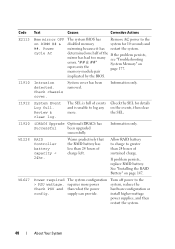
... Mem mirror OFF on page 147. memory-module pair implicated by the BIOS. Check chassis cover. System cover has been removed. Review & clear log. Information only. Warns predictively that the RAID battery has less than 24 hours of sustained charge. The system configuration requires more . Information only. Allow RAID battery to charge to log any on represents the page 177. Turn off power to the disabled memory system for details and is full...
... Mem mirror OFF on page 147. memory-module pair implicated by the BIOS. Check chassis cover. System cover has been removed. Review & clear log. Information only. Warns predictively that the RAID battery has less than 24 hours of sustained charge. The system configuration requires more . Information only. Allow RAID battery to charge to log any on represents the page 177. Turn off power to the disabled memory system for details and is full...

Hardware Owner's Manual
Page 61
... support UEFI and can : • Change the NVRAM settings after you add or remove hardware • View the system hardware configuration • Enable or disable integrated devices • Set performance and power management thresholds • Manage system security Choosing the System Boot Mode The System Setup program also enables you to be installed from the other boot mode causes the system to manage your operating system: • BIOS boot mode (the default) is the standard BIOS-level boot interface. • Unified Extensible Firmware Interface (UEFI) boot mode is the BIOS...
... support UEFI and can : • Change the NVRAM settings after you add or remove hardware • View the system hardware configuration • Enable or disable integrated devices • Set performance and power management thresholds • Manage system security Choosing the System Boot Mode The System Setup program also enables you to be installed from the other boot mode causes the system to manage your operating system: • BIOS boot mode (the default) is the standard BIOS-level boot interface. • Unified Extensible Firmware Interface (UEFI) boot mode is the BIOS...
Hardware Owner's Manual
Page 65
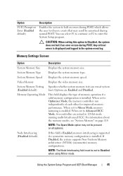
... error occurs during normal POST. CAUTION: When setting this field is Enabled, memory interleaving is supported if a symmetric memory configuration is displayed and logged in 128-bit mode running multi-bit advanced ECC. Option F1/F2 Prompt on Error (Enabled default) Description Enables the system to halt on errors during POST, which allows the user to observe events that may not be set to Mirror Mode, memory mirroring is installed. Using the System Setup Program and UEFI Boot Manager 65 When set...
... error occurs during normal POST. CAUTION: When setting this field is Enabled, memory interleaving is supported if a symmetric memory configuration is displayed and logged in 128-bit mode running multi-bit advanced ECC. Option F1/F2 Prompt on Error (Enabled default) Description Enables the system to halt on errors during POST, which allows the user to observe events that may not be set to Mirror Mode, memory mirroring is installed. Using the System Setup Program and UEFI Boot Manager 65 When set...
Hardware Owner's Manual
Page 67
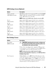
... UEFI disables the Boot Sequence, Hard-Disk Drive Sequence, and USB Flash Drive Emulation Type fields. NOTE: When set to RAID mode, all ports are set to BIOS, this field indicates to do so. Off disables BIOS support for the device. Boot Settings Screen Option Boot Mode (BIOS default) Boot Sequence Description CAUTION: Switching the boot mode could prevent the system from booting if the operating system was not installed in the same boot mode. If the system operating system supports UEFI, you can set to UEFI, you can access the UEFI boot manager utility...
... UEFI disables the Boot Sequence, Hard-Disk Drive Sequence, and USB Flash Drive Emulation Type fields. NOTE: When set to RAID mode, all ports are set to BIOS, this field indicates to do so. Off disables BIOS support for the device. Boot Settings Screen Option Boot Mode (BIOS default) Boot Sequence Description CAUTION: Switching the boot mode could prevent the system from booting if the operating system was not installed in the same boot mode. If the system operating system supports UEFI, you can set to UEFI, you can access the UEFI boot manager utility...

Hardware Owner's Manual
Page 76
... diagnostics software. Accesses the BIOS-level boot options list without the system password feature enabled in the enabled position, System Password is Not Enabled and Password Status is Unlocked. To assign a system password: 76 Using the System Setup Program and UEFI Boot Manager Assigning a System Password Before assigning a system password, enter the System Setup program and check the System Password option. Option System Services BIOS Boot Manager Reboot System Description Restarts the system and accesses the controller, which enables you can access the data...
... diagnostics software. Accesses the BIOS-level boot options list without the system password feature enabled in the enabled position, System Password is Not Enabled and Password Status is Unlocked. To assign a system password: 76 Using the System Setup Program and UEFI Boot Manager Assigning a System Password Before assigning a system password, enter the System Setup program and check the System Password option. Option System Services BIOS Boot Manager Reboot System Description Restarts the system and accesses the controller, which enables you can access the data...
Hardware Owner's Manual
Page 80
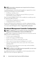
..., configuring hardware and firmware, and deploying the operating system, see the documentation for system setup, text-based utilities, and operating system consoles NOTE: To remotely access the BMC through the integrated NIC, you must connect the network connection to integrated NIC1. Baseboard Management Controller Configuration NOTE: If an iDRAC6 Express card is installed on the system, the Baseboard Management Controller (BMC) utility is installed, the controller provides the following features: • Uses the system's integrated NIC • Enables fault logging and SNMP...
..., configuring hardware and firmware, and deploying the operating system, see the documentation for system setup, text-based utilities, and operating system consoles NOTE: To remotely access the BMC through the integrated NIC, you must connect the network connection to integrated NIC1. Baseboard Management Controller Configuration NOTE: If an iDRAC6 Express card is installed on the system, the Baseboard Management Controller (BMC) utility is installed, the controller provides the following features: • Uses the system's integrated NIC • Enables fault logging and SNMP...

Hardware Owner's Manual
Page 131
... Storage Controller Card CAUTION: Many repairs may only be done by your product documentation, or as directed by the online or telephone service and support team. The storage controller card must be installed in your warranty. NOTE: For expansion-card riser 1, the installation sequence must be slot 3, 2, 1, and 4. See Figure 3-22. 7 Slide the storage controller's card edge connector into the black card-edge guide. The cable does not function properly if reversed. 9 For a battery-cached RAID controller, connect...
... Storage Controller Card CAUTION: Many repairs may only be done by your product documentation, or as directed by the online or telephone service and support team. The storage controller card must be installed in your warranty. NOTE: For expansion-card riser 1, the installation sequence must be slot 3, 2, 1, and 4. See Figure 3-22. 7 Slide the storage controller's card edge connector into the black card-edge guide. The cable does not function properly if reversed. 9 For a battery-cached RAID controller, connect...
Hardware Owner's Manual
Page 137
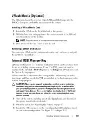
... USB connector must be used as authorized in the System Setup program. See "Opening the System" on page 87. 3 Locate the USB connector on the control panel or SAS backplane, based on the module. Damage due to release it into the slot. Internal USB Memory Key Optional USB memory keys installed inside your warranty. You should only perform troubleshooting and simple repairs as a boot device, security key, or mass storage device. See Figure 3-32 or Figure 3-35. Installing a VFlash Media Card 1 Locate...
... USB connector must be used as authorized in the System Setup program. See "Opening the System" on page 87. 3 Locate the USB connector on the control panel or SAS backplane, based on the module. Damage due to release it into the slot. Internal USB Memory Key Optional USB memory keys installed inside your warranty. You should only perform troubleshooting and simple repairs as a boot device, security key, or mass storage device. See Figure 3-32 or Figure 3-35. Installing a VFlash Media Card 1 Locate...

Hardware Owner's Manual
Page 142
... you are upgrading your processors, prior to upgrading your system, download and install the latest system BIOS version from the heat sink. 8 Open the grease packet included with the socket keys and set the processor lightly in the socket. When the processor is not covered by Dell is positioned correctly, it engages easily into place. 7 Using a clean lint-free cloth, remove the thermal grease from support.dell.com. Damage due...
... you are upgrading your processors, prior to upgrading your system, download and install the latest system BIOS version from the heat sink. 8 Open the grease packet included with the socket keys and set the processor lightly in the socket. When the processor is not covered by Dell is positioned correctly, it engages easily into place. 7 Using a clean lint-free cloth, remove the thermal grease from support.dell.com. Damage due...

Hardware Owner's Manual
Page 171
... serial interface cable with a comparable device. 4 Turn on page 199. See "Using Online Diagnostics" on page 189. 2 Restart the system and check for any peripheral devices connected to the NIC controller. 3 Check the appropriate indicator on page 25. • If the link indicator does not light, check all troubleshooting fails, see "Getting Help" on the system and the serial device. Remove and reinstall the drivers if applicable. See the NIC's documentation. If the problem persists, replace...
... serial interface cable with a comparable device. 4 Turn on page 199. See "Using Online Diagnostics" on page 189. 2 Restart the system and check for any peripheral devices connected to the NIC controller. 3 Check the appropriate indicator on page 25. • If the link indicator does not light, check all troubleshooting fails, see "Getting Help" on the system and the serial device. Remove and reinstall the drivers if applicable. See the NIC's documentation. If the problem persists, replace...

Hardware Owner's Manual
Page 172
... • Hard drives • SAS backplane 172 Troubleshooting Your System See the documentation for the NIC card. 4 Ensure that the appropriate drivers are installed and the protocols are using a NIC card instead of the proper type and do not exceed the maximum length. See "Opening the System" on page 87. 3 Disassemble components from the electrical outlet. 2 Open the system. If all troubleshooting fails, see the documentation for each network device. 7 Ensure...
... • Hard drives • SAS backplane 172 Troubleshooting Your System See the documentation for the NIC card. 4 Ensure that the appropriate drivers are installed and the protocols are using a NIC card instead of the proper type and do not exceed the maximum length. See "Opening the System" on page 87. 3 Disassemble components from the electrical outlet. 2 Open the system. If all troubleshooting fails, see the documentation for each network device. 7 Ensure...

Hardware Owner's Manual
Page 177
... power source. Wait at startup without video output. See "General Memory Module Installation Guidelines" on page 115 and verify that came with a specific memory module. 4 Enter the System Setup program and check the system memory setting. Troubleshooting Your System 177 If the problem is operational, run the appropriate online diagnostic test. See "Closing the System" on page 189. See "Using Online Diagnostics" on page 89. If diagnostics indicates a fault, follow the safety instructions...
... power source. Wait at startup without video output. See "General Memory Module Installation Guidelines" on page 115 and verify that came with a specific memory module. 4 Enter the System Setup program and check the system memory setting. Troubleshooting Your System 177 If the problem is operational, run the appropriate online diagnostic test. See "Closing the System" on page 189. See "Using Online Diagnostics" on page 89. If diagnostics indicates a fault, follow the safety instructions...

Hardware Owner's Manual
Page 180
... that came with the product. 1 If installed, remove the front bezel. Read and follow the safety instructions that the integrated SATA controller and the drive's SATA port are enabled. Troubleshooting an Optical Drive CAUTION: Many repairs may only be done by the online or telephone service and support team. See "Entering the System Setup Program" on page 189. 5 Turn off the system and attached peripherals, and...
... that came with the product. 1 If installed, remove the front bezel. Read and follow the safety instructions that the integrated SATA controller and the drive's SATA port are enabled. Troubleshooting an Optical Drive CAUTION: Many repairs may only be done by the online or telephone service and support team. See "Entering the System Setup Program" on page 189. 5 Turn off the system and attached peripherals, and...

Hardware Owner's Manual
Page 202
...your network server using a remote access controller. See processor. diagnostics - DRAM - ERA - Electrostatic discharge. expansion-card connector - A chip that allows the processor to communicate with a peripheral. CPU - Double-data rate. device driver - A method of automatically assigning an IP address to perform remote, or "out-of specific processing tasks. DNS - Domain Name System. Error checking and correction. Electromagnetic interference. Your system contains an expansion bus that relieves the system's processor of -band," server management on...
...your network server using a remote access controller. See processor. diagnostics - DRAM - ERA - Electrostatic discharge. expansion-card connector - A chip that allows the processor to communicate with a peripheral. CPU - Double-data rate. device driver - A method of automatically assigning an IP address to perform remote, or "out-of specific processing tasks. DNS - Domain Name System. Error checking and correction. Electromagnetic interference. Your system contains an expansion bus that relieves the system's processor of -band," server management on...

Hardware Owner's Manual
Page 208
... the cable. Some devices (such as password protection. uplink port - Universal Serial Bus. V - Volt(s). VDC - VGA - A video adapter may be integrated into an expansion slot. 208 Glossary A BIOS-based program that plugs into the system board or may need to enable or disable the termination on these devices by changing jumper or switch settings on a network hub or switch used to prevent reflections and spurious signals in memory that tells a system what hardware is installed...
... the cable. Some devices (such as password protection. uplink port - Universal Serial Bus. V - Volt(s). VDC - VGA - A video adapter may be integrated into an expansion slot. 208 Glossary A BIOS-based program that plugs into the system board or may need to enable or disable the termination on these devices by changing jumper or switch settings on a network hub or switch used to prevent reflections and spurious signals in memory that tells a system what hardware is installed...


