
Glossary
Page 1
... DMTF. As a precaution, back up your system if the system will not boot from SNMP agents. A module that includes power supplies and fans. British thermal unit. bus - Certificate authority. CIM - It provides mapping techniques for interchange of CIM data with ...BMC - C - Centimeter(s). 1 American National Standards Institute. BTU - Your system contains an expansion bus that is located. ACPI - Dell™ Glossary NOTE: For additional information on storage terminology, visit the Storage Networking Industry Association's website at www.snia.org and click ...
... DMTF. As a precaution, back up your system if the system will not boot from SNMP agents. A module that includes power supplies and fans. British thermal unit. bus - Certificate authority. CIM - It provides mapping techniques for interchange of CIM data with ...BMC - C - Centimeter(s). 1 American National Standards Institute. BTU - Your system contains an expansion bus that is located. ACPI - Dell™ Glossary NOTE: For additional information on storage terminology, visit the Storage Networking Industry Association's website at www.snia.org and click ...

Glossary
Page 8
... jumper or switch settings on each disk used to connect to other hubs or switches without requiring a crossover cable. Uninterruptible power supply. USB memory key - SVGA - A virtual disk may need to configure your system's hardware and customize the system's...peripherals, and various ROM chips. TCP/IP offload engine. An unregistered (unbuffered) DDR3 memory module. UPS - A battery-powered unit that automatically supplies power to I/O devices. A USB connector provides a single connection point for multiple USB-compliant devices, such as the processor(s), ...
... jumper or switch settings on each disk used to connect to other hubs or switches without requiring a crossover cable. Uninterruptible power supply. USB memory key - SVGA - A virtual disk may need to configure your system's hardware and customize the system's...peripherals, and various ROM chips. TCP/IP offload engine. An unregistered (unbuffered) DDR3 memory module. UPS - A battery-powered unit that automatically supplies power to I/O devices. A USB connector provides a single connection point for multiple USB-compliant devices, such as the processor(s), ...

Glossary
Page 48
Super video graphics array VGA と SVGA TCP/IP - Transmission Control Protocol/Internet Protocol TOE - Uninterruptible power supply USB - Volts alternating current VDC - Universal Serial Bus USB USB USB USB V - Volt VAC - Windows Management Instrumentation。CIM ZIF - Volt direct current VGA - Watt-...
Super video graphics array VGA と SVGA TCP/IP - Transmission Control Protocol/Internet Protocol TOE - Uninterruptible power supply USB - Volts alternating current VDC - Universal Serial Bus USB USB USB USB V - Volt VAC - Windows Management Instrumentation。CIM ZIF - Volt direct current VGA - Watt-...

Glossary
Page 58
...TCP/IP Transmission Control Protocol/Internet Protocol TOE - TCP/IP TCP/IP Offload Engine U-DIMM DDR3 Unregistered(Unbuffered) DDR3 Memory Module UPS Uninterruptible Power Supply USB Universal Serial Bus USB USB USB USB V - 볼트 (Volt VAC Volt Alternating Current VDC Volt Direct Current VGA Video Graphics...; (Watt WH Watt-Hour WMI - Windows Management Instrumentation 은 CIM ZIF Zero Insertion Force provider CIM management station managed system) 은 Dell OpenManage™ Server Administrator x x y x z 58
...TCP/IP Transmission Control Protocol/Internet Protocol TOE - TCP/IP TCP/IP Offload Engine U-DIMM DDR3 Unregistered(Unbuffered) DDR3 Memory Module UPS Uninterruptible Power Supply USB Universal Serial Bus USB USB USB USB V - 볼트 (Volt VAC Volt Alternating Current VDC Volt Direct Current VGA Video Graphics...; (Watt WH Watt-Hour WMI - Windows Management Instrumentation 은 CIM ZIF Zero Insertion Force provider CIM management station managed system) 은 Dell OpenManage™ Server Administrator x x y x z 58

Getting Started Guide
Page 4
Plug the other end of the power cable(s) into a grounded electrical outlet or a separate power source such as shown in the illustration, and attach to the monitor. Connecting The Power Cable(s) Figure 3. Connecting the Power Cable(s) Connect the system's power cable(s) to the system and, if a monitor is used, connect the monitor's power cable to the cable strap. Securing The Power Cable(s) Figure 4. Securing the Power Cable(s) Bend the system power cable(s), as an uninterruptible power supply (UPS) or a power distribution unit (PDU). 4
Plug the other end of the power cable(s) into a grounded electrical outlet or a separate power source such as shown in the illustration, and attach to the monitor. Connecting The Power Cable(s) Figure 3. Connecting the Power Cable(s) Connect the system's power cable(s) to the system and, if a monitor is used, connect the monitor's power cable to the cable strap. Securing The Power Cable(s) Figure 4. Securing the Power Cable(s) Bend the system power cable(s), as an uninterruptible power supply (UPS) or a power distribution unit (PDU). 4
Getting Started Guide
Page 6
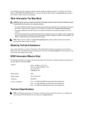
... 100 V CA-240 V CA 50 Hz/60 Hz 7.4 A - 3.7 A (X2) (with 550 W Redundant AC Power Supply Unit) 7.4 A - 3.7 A (with 550 W Non-redundant AC Power Supply Unit) 4.8 A - 2.4 A (X2) (with 350 W Redundant AC Power Supply Unit) Technical Specifications NOTE: The following information is available online at support.dell.com/manuals. • The rack documentation included with your rack solution describes how...
... 100 V CA-240 V CA 50 Hz/60 Hz 7.4 A - 3.7 A (X2) (with 550 W Redundant AC Power Supply Unit) 7.4 A - 3.7 A (with 550 W Non-redundant AC Power Supply Unit) 4.8 A - 2.4 A (X2) (with 350 W Redundant AC Power Supply Unit) Technical Specifications NOTE: The following information is available online at support.dell.com/manuals. • The rack documentation included with your rack solution describes how...
Getting Started Guide
Page 7
... range and configurations, see dell.com/environmental_datasheets. Storage Relative humidity -40 °C to 65 °C (-40 °F to 80% relative humidity (RH), with 26 °C max dew point. Temperature Operating Continuous operation: 10 °C to 35 °C at 1 °C/300 m above 900 m (1 °F per hour 7 Power AC Power Supply (per power supply) Wattage 350 W and 550...
... range and configurations, see dell.com/environmental_datasheets. Storage Relative humidity -40 °C to 65 °C (-40 °F to 80% relative humidity (RH), with 26 °C max dew point. Temperature Operating Continuous operation: 10 °C to 35 °C at 1 °C/300 m above 900 m (1 °F per hour 7 Power AC Power Supply (per power supply) Wattage 350 W and 550...
Owner's Manual
Page 5
... Storage Controller Card 74 Processors...74 Removing A Processor...74 Installing A Processor...76 Power Supplies...77 Hot Spare Feature...78 Removing A Redundant Power Supply...78 Installing A Redundant Power Supply...79 Removing A Non-Redundant Power Supply...79 Installing A Non-Redundant Power Supply...80 Removing The Power Supply Blank...81 Installing The Power Supply Blank...81 System Battery...81 Replacing The System Battery...81 Hard-Drive Backplane...
... Storage Controller Card 74 Processors...74 Removing A Processor...74 Installing A Processor...76 Power Supplies...77 Hot Spare Feature...78 Removing A Redundant Power Supply...78 Installing A Redundant Power Supply...79 Removing A Non-Redundant Power Supply...79 Installing A Non-Redundant Power Supply...80 Removing The Power Supply Blank...81 Installing The Power Supply Blank...81 System Battery...81 Replacing The System Battery...81 Hard-Drive Backplane...
Owner's Manual
Page 6
... Troubleshooting A USB Device...101 Troubleshooting A Serial I/O Device...102 Troubleshooting A NIC...102 Troubleshooting A Wet System...102 Troubleshooting A Damaged System...103 Troubleshooting The System Battery...104 Troubleshooting Power Supplies...104 Troubleshooting Cooling Problems...104 Troubleshooting Cooling Fans...105 Troubleshooting System Memory...105 Troubleshooting An Internal USB Key...106 Troubleshooting An SD Card...106 Troubleshooting...
... Troubleshooting A USB Device...101 Troubleshooting A Serial I/O Device...102 Troubleshooting A NIC...102 Troubleshooting A Wet System...102 Troubleshooting A Damaged System...103 Troubleshooting The System Battery...104 Troubleshooting Power Supplies...104 Troubleshooting Cooling Problems...104 Troubleshooting Cooling Fans...105 Troubleshooting System Memory...105 Troubleshooting An Internal USB Key...106 Troubleshooting An SD Card...106 Troubleshooting...
Owner's Manual
Page 9
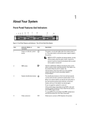
... the system ID on . 1 About Your System Front-Panel Features And Indicators Figure 1. Press to enter BIOS progress mode. The power button controls the power supply output to the system. 9 To reset iDRAC (if not disabled in F2 iDRAC setup) press and hold the system ID button...Front-Panel Features and Indicators-Four 3.5 Inch Hard-Drive System Item Indicator, Button, or Icon Description Connector 1 Power-on indicator, power button The power-on indicator lights when the system power is turned off . When one of these buttons is pressed, the LCD panel on the front and the ...
... the system ID on . 1 About Your System Front-Panel Features And Indicators Figure 1. Press to enter BIOS progress mode. The power button controls the power supply output to the system. 9 To reset iDRAC (if not disabled in F2 iDRAC setup) press and hold the system ID button...Front-Panel Features and Indicators-Four 3.5 Inch Hard-Drive System Item Indicator, Button, or Icon Description Connector 1 Power-on indicator, power button The power-on indicator lights when the system power is turned off . When one of these buttons is pressed, the LCD panel on the front and the ...
Owner's Manual
Page 10
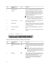
...per your need. One optional slim SATA DVD-ROM drive or DVD+/-RW drive. Up to the system. Figure 2. The power button controls the power supply output to four 3.5 inch or 2.5 inch hot-swappable hard drives, or SSDs. The LCD lights amber when the system needs...-Panel Features and Indicators-Eight 2.5 Inch Hard-Drive System Item Indicator, Button, or Icon Description Connector 1 Power-on indicator, power button The power-on indicator lights when the system power is detected, the LCD lights amber regardless of a paper clip. Item Indicator, Button, or Icon Description Connector...
...per your need. One optional slim SATA DVD-ROM drive or DVD+/-RW drive. Up to the system. Figure 2. The power button controls the power supply output to four 3.5 inch or 2.5 inch hot-swappable hard drives, or SSDs. The LCD lights amber when the system needs...-Panel Features and Indicators-Eight 2.5 Inch Hard-Drive System Item Indicator, Button, or Icon Description Connector 1 Power-on indicator, power button The power-on indicator lights when the system power is detected, the LCD lights amber regardless of a paper clip. Item Indicator, Button, or Icon Description Connector...
Owner's Manual
Page 12
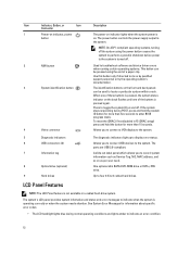
... Indicator, Button, or Icon Description Connector 1 Power-on indicator, power button The power-on indicator lights when the system power is on the front and back panels can be pressed using the power button causes the system to perform a graceful shutdown before power to the system is turned off. 2 NMI... (2) 7 Information tag 8 Optical drive (optional) 9 Hard drives The diagnostic indicators light up to locate a particular system within a rack. The power button controls the power supply output to the system. Allows you to connect USB devices to the system.
... Indicator, Button, or Icon Description Connector 1 Power-on indicator, power button The power-on indicator lights when the system power is on the front and back panels can be pressed using the power button causes the system to perform a graceful shutdown before power to the system is turned off. 2 NMI... (2) 7 Information tag 8 Optical drive (optional) 9 Hard drives The diagnostic indicators light up to locate a particular system within a rack. The power button controls the power supply output to the system. Allows you to connect USB devices to the system.
Owner's Manual
Page 15
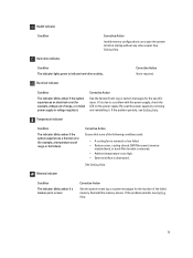
... is removed. • Ambient temperature is too high. • External airflow is due to a problem with the power supply, check the LED on the power supply. Hard-drive indicator Condition The indicator lights green to halt at startup without any video output. If it . If... the problem persists, see Getting Help. 15 See Getting Help. Corrective Action Ensure that none of range, or a failed power supply or voltage regulator). Reinstall the memory device. Corrective Action None required. Health indicator Condition Corrective Action Invalid memory configurations can cause ...
... is removed. • Ambient temperature is too high. • External airflow is due to a problem with the power supply, check the LED on the power supply. Hard-drive indicator Condition The indicator lights green to halt at startup without any video output. If it . If... the problem persists, see Getting Help. 15 See Getting Help. Corrective Action Ensure that none of range, or a failed power supply or voltage regulator). Reinstall the memory device. Corrective Action None required. Health indicator Condition Corrective Action Invalid memory configurations can cause ...

Owner's Manual
Page 17
...PCIe expansion card slot 2 6 Video connector 7 Ethernet connectors (2) 8 USB connectors (2) 9 System identification connector 10 System identification button 11 Power supply (PSU1) 12 Power supply (PSU2) Description Allows you to connect a full-height PCI Express expansion card. Allows you to the system. Connects the optional system status...and hold the system ID button for more than 15 seconds. 350 W and 550 W NOTE: For non-redundant power supply units, there is pressed again. Integrated 10/100/1000 Mbps NIC connector. The identification buttons on the front and back...
...PCIe expansion card slot 2 6 Video connector 7 Ethernet connectors (2) 8 USB connectors (2) 9 System identification connector 10 System identification button 11 Power supply (PSU1) 12 Power supply (PSU2) Description Allows you to connect a full-height PCI Express expansion card. Allows you to the system. Connects the optional system status...and hold the system ID button for more than 15 seconds. 350 W and 550 W NOTE: For non-redundant power supply units, there is pressed again. Integrated 10/100/1000 Mbps NIC connector. The identification buttons on the front and back...

Owner's Manual
Page 18
... to a valid network at less than its maximum port speed (1 Gbps or 10 Gbps). Activity indicator is blinking green Network data is present or whether a power fault has occurred. Power Supply Status Indicator 1. NIC Indicator Codes Figure 7. Link indicator is amber The NIC is connected to a valid network at its maximum port speed...
... to a valid network at less than its maximum port speed (1 Gbps or 10 Gbps). Activity indicator is blinking green Network data is present or whether a power fault has occurred. Power Supply Status Indicator 1. NIC Indicator Codes Figure 7. Link indicator is amber The NIC is connected to a valid network at its maximum port speed...
Owner's Manual
Page 19
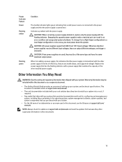
... as a separate document. • The Getting Started Guide provides an overview of the other installed power supply. CAUTION: AC power supplies support both 220 V and 110 V input voltages. When hot-adding a power supply, this document, see the Glossary at support.dell.com/manuals. • The rack documentation included with your rack solution describes how to install your...
... as a separate document. • The Getting Started Guide provides an overview of the other installed power supply. CAUTION: AC power supplies support both 220 V and 110 V input voltages. When hot-adding a power supply, this document, see the Glossary at support.dell.com/manuals. • The rack documentation included with your rack solution describes how to install your...
Owner's Manual
Page 38
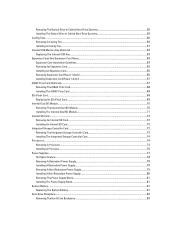
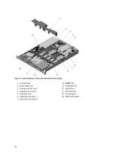
Inside the System-With a Non-Redundant Power Supply 1. heat sink for processor 2 8. cooling shroud 2. expansion-card riser 2 5. hard drives (4) 12. power supply unit 3. optical drive 11. front I/O panel 13. Figure 11. storage controller card 4. expansion card 6. expansion-card riser 1 7. DIMMs (12) 9. cable routing latch 38 cooling fans (5) 10.
Inside the System-With a Non-Redundant Power Supply 1. heat sink for processor 2 8. cooling shroud 2. expansion-card riser 2 5. hard drives (4) 12. power supply unit 3. optical drive 11. front I/O panel 13. Figure 11. storage controller card 4. expansion card 6. expansion-card riser 1 7. DIMMs (12) 9. cable routing latch 38 cooling fans (5) 10.
Owner's Manual
Page 39
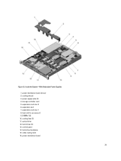
Figure 12. power supply units (2) 4. expansion card 7. control panel 14. power distribution board 39 expansion-card riser 1 8. hard-drive backplane 15. cable routing latch 16. cooling shroud 3. expansion-card riser 2 6. hard drives (4) 13. heat sink for processor 2 9. cooling fans (5) 11. DIMMs (12) 10. optical drive 12. power distribution board shroud 2. storage controller card 5. Inside the System-With Redundant Power Supplies 1.
Figure 12. power supply units (2) 4. expansion card 7. control panel 14. power distribution board 39 expansion-card riser 1 8. hard-drive backplane 15. cable routing latch 16. cooling shroud 3. expansion-card riser 2 6. hard drives (4) 13. heat sink for processor 2 9. cooling fans (5) 11. DIMMs (12) 10. optical drive 12. power distribution board shroud 2. storage controller card 5. Inside the System-With Redundant Power Supplies 1.

Owner's Manual
Page 60
... fan is referenced by the system's management software, allowing you to the SATA connector on may only be installed in a non-redundant power supply configuration. • Up to the back of the optical drive. 5. Connect the data cable to six cooling fans in your product ...not supported. Read and follow the safety instructions that is not authorized by Dell is on the system board. Connect the power cable. 7. Cooling Fans Your system supports: • Up to five cooling fans in a redundant power supply configuration. NOTE: Fan 1 must be done by noting the fan numbers...
... fan is referenced by the system's management software, allowing you to the SATA connector on may only be installed in a non-redundant power supply configuration. • Up to the back of the optical drive. 5. Connect the data cable to six cooling fans in your product ...not supported. Read and follow the safety instructions that is not authorized by Dell is on the system board. Connect the power cable. 7. Cooling Fans Your system supports: • Up to five cooling fans in a redundant power supply configuration. NOTE: Fan 1 must be done by noting the fan numbers...

Owner's Manual
Page 76
... slot, and upgrade both the riser cards (riser1 and riser 2). NOTE: If you install a second processor, you upgrade to 550 W redundant power supply, to servicing that you must be done by a certified service technician. NOTE: When installing a second processor in socket CPU1. Installing A Processor .... 76 processor 2. Read and follow the safety instructions that came with a 350 W redundant power supply, it is not covered by your product documentation, or as directed by Dell is highly recommended that is not authorized by the online or telephone service and support team. Figure...
... slot, and upgrade both the riser cards (riser1 and riser 2). NOTE: If you install a second processor, you upgrade to 550 W redundant power supply, to servicing that you must be done by a certified service technician. NOTE: When installing a second processor in socket CPU1. Installing A Processor .... 76 processor 2. Read and follow the safety instructions that came with a 350 W redundant power supply, it is not covered by your product documentation, or as directed by Dell is highly recommended that is not authorized by the online or telephone service and support team. Figure...


