
Glossary
Page 2
...-data rate. diagnostics - Error checking and correction. EMI - The part of the system that relieves the system's processor of specific processing tasks. A method of translating Internet domain names, such as NICs. DNS - Domain Name System. Digital versatile disc or digital video disc. A math coprocessor, for the serial ports on your network server using a remote access controller. DHCP - Dynamic Host Configuration Protocol. DIMM - Dual in memory modules that plugs into IP addresses, such...
...-data rate. diagnostics - Error checking and correction. EMI - The part of the system that relieves the system's processor of specific processing tasks. A method of translating Internet domain names, such as NICs. DNS - Domain Name System. Digital versatile disc or digital video disc. A math coprocessor, for the serial ports on your network server using a remote access controller. DHCP - Dynamic Host Configuration Protocol. DIMM - Dual in memory modules that plugs into IP addresses, such...

Glossary
Page 3
... storage devices. IDE - A standard interface between the processor and the main memory (RAM). Internet Protocol. F - Fahrenheit. flash memory - Gram(s). GB - Gigabyte(s); 1024 megabytes or 1,073,741,824 bytes. graphics mode - In general, I /O - A high-speed network interface used by z colors. The ability to -point bidirectional serial links intended for plugging in an expansion card. IP - The FSB is an output device. File transfer protocol. Gravities. Gb - Hz - Integrated Dell Remote Access Controller. hot...
... storage devices. IDE - A standard interface between the processor and the main memory (RAM). Internet Protocol. F - Fahrenheit. flash memory - Gram(s). GB - Gigabyte(s); 1024 megabytes or 1,073,741,824 bytes. graphics mode - In general, I /O - A high-speed network interface used by z colors. The ability to -point bidirectional serial links intended for plugging in an expansion card. IP - The FSB is an output device. File transfer protocol. Gravities. Gb - Hz - Integrated Dell Remote Access Controller. hot...

Glossary
Page 8
... a network hub or switch used . TCP/IP offload engine. Uninterruptible power supply. Universal Serial Bus. See also guarding, mirroring, and RAID. Super video graphics array. VGA and SVGA are connected in a series, you change them again. An unregistered (unbuffered) DDR3 memory module. SNMP - Disk striping writes data across three or more processors connected via a high-bandwidth link and managed by changing settings in memory that allows a network manager to other hubs or switches without requiring a crossover cable. Transmission Control Protocol...
... a network hub or switch used . TCP/IP offload engine. Uninterruptible power supply. Universal Serial Bus. See also guarding, mirroring, and RAID. Super video graphics array. VGA and SVGA are connected in a series, you change them again. An unregistered (unbuffered) DDR3 memory module. SNMP - Disk striping writes data across three or more processors connected via a high-bandwidth link and managed by changing settings in memory that allows a network manager to other hubs or switches without requiring a crossover cable. Transmission Control Protocol...
Owner's Manual
Page 12
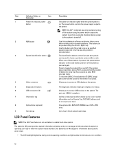
... stops responding during normal operating conditions and lights amber to enter BIOS progress mode. To reset the iDRAC (if not disabled in a cabled hard-drive system. A slide-out label panel which allows you to record system information such as Service Tag, NIC, MAC address, and so on and off . 2 NMI button 3 System identification button 4 Video connector Used to troubleshoot software and device driver errors when running certain operating systems. This button can be pressed using the power button causes the system...
... stops responding during normal operating conditions and lights amber to enter BIOS progress mode. To reset the iDRAC (if not disabled in a cabled hard-drive system. A slide-out label panel which allows you to record system information such as Service Tag, NIC, MAC address, and so on and off . 2 NMI button 3 System identification button 4 Video connector Used to troubleshoot software and device driver errors when running certain operating systems. This button can be pressed using the power button causes the system...
Owner's Manual
Page 21
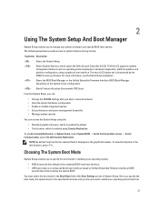
... installing your operating system: • BIOS boot mode (the default) is the standard BIOS-level boot interface. • UEFI boot mode is displayed in the graphical browser. Choosing The System Boot Mode System Setup enables you add or remove hardware • View the system hardware configuration • Enable or disable integrated devices • Set performance and power management thresholds • Manage system security You can : • Change the NVRAM settings after you to specify the boot mode for the selected field is an enhanced 64-bit boot interface...
... installing your operating system: • BIOS boot mode (the default) is the standard BIOS-level boot interface. • UEFI boot mode is displayed in the graphical browser. Choosing The System Boot Mode System Setup enables you add or remove hardware • View the system hardware configuration • Enable or disable integrated devices • Set performance and power management thresholds • Manage system security You can : • Change the NVRAM settings after you to specify the boot mode for the selected field is an enhanced 64-bit boot interface...
Owner's Manual
Page 23
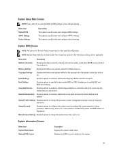
... Setup change the processor power management settings, memory frequency, and so on . Memory Settings Displays information and options related to the processor such as the system model name, BIOS version, Service Tag, and so on the system. 23 Processor Settings Displays information and options related to installed memory. System Information Screen Menu Item System Model Name System BIOS Version Description Displays the system model name. It also enables or disables the power and NMI buttons on the system configuration. This option is used...
... Setup change the processor power management settings, memory frequency, and so on . Memory Settings Displays information and options related to the processor such as the system model name, BIOS version, Service Tag, and so on the system. 23 Processor Settings Displays information and options related to installed memory. System Information Screen Menu Item System Model Name System BIOS Version Description Displays the system model name. It also enables or disables the power and NMI buttons on the system configuration. This option is used...
Owner's Manual
Page 26
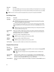
... Port D is installed on the system. Auto enables BIOS support for the device attached to UEFI disables BIOS Boot Settings menu. NOTE: Ports A, B, C, and D are used for the backplane drives, and port E for the optical drive (CD/DVD). Boot Settings Screen Menu Item Boot Mode Boot Sequence Retry BIOS Boot Settings UEFI Boot Settings One-Time Boot Description Allows you to enable or disable the boot sequence retry feature. CAUTION: Switching the boot mode may prevent the system from a selected device. If this field to SATA port D. By default, the User Accessible USB Ports...
... Port D is installed on the system. Auto enables BIOS support for the device attached to UEFI disables BIOS Boot Settings menu. NOTE: Ports A, B, C, and D are used for the backplane drives, and port E for the optical drive (CD/DVD). Boot Settings Screen Menu Item Boot Mode Boot Sequence Retry BIOS Boot Settings UEFI Boot Settings One-Time Boot Description Allows you to enable or disable the boot sequence retry feature. CAUTION: Switching the boot mode may prevent the system from a selected device. If this field to SATA port D. By default, the User Accessible USB Ports...
Owner's Manual
Page 27
... installed on both the Option ROM and UEFI driver are disabled. To use console redirection by SOL, configure the same port address for console redirection and the serial device. NOTE: This option is displayed only if IDSDM is set the port address for Serial Over LAN (SOL). Slot Disablement Allows you to Enabled. Serial Communications Screen Menu Item Description Serial Communication Allows you to set to Mirror mode, data is written on the system board. Menu Item Internal SD Card Port Description Enables or disables...
... installed on both the Option ROM and UEFI driver are disabled. To use console redirection by SOL, configure the same port address for console redirection and the serial device. NOTE: This option is displayed only if IDSDM is set the port address for Serial Over LAN (SOL). Slot Disablement Allows you to Enabled. Serial Communications Screen Menu Item Description Serial Communication Allows you to set to Mirror mode, data is written on the system board. Menu Item Internal SD Card Port Description Enables or disables...
Owner's Manual
Page 34
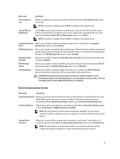
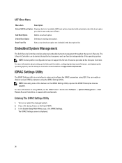
... Controller documentation at support.dell.com/manuals. In the System Setup Main Menu page, click iDRAC Settings. The iDRAC Settings screen is an interface to use and press . Boot From File Sets a one-time boot option not included in the boot option list. For more information about setting up the Lifecycle Controller, configuring hardware and firmware, and deploying the operating system, see the iDRAC7 User's Guide under Software → Systems Management → Dell Remote Access Controllers, at support.dell.com/manuals. Embedded System Management...
... Controller documentation at support.dell.com/manuals. In the System Setup Main Menu page, click iDRAC Settings. The iDRAC Settings screen is an interface to use and press . Boot From File Sets a one-time boot option not included in the boot option list. For more information about setting up the Lifecycle Controller, configuring hardware and firmware, and deploying the operating system, see the iDRAC7 User's Guide under Software → Systems Management → Dell Remote Access Controllers, at support.dell.com/manuals. Embedded System Management...
Owner's Manual
Page 69
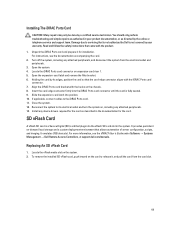
.... 12. Replacing An SD vFlash Card 1. To remove the installed SD vFlash card, push inward on , including any attached peripherals. 13. For instructions, see the iDRAC7 User's Guide under Software → Systems Management → Dell Remote Access Controllers, at support.dell.com/manuals. Locate the iDRAC Ports card connector on the system. 2. It emulates USB device(s). Open the system. 4. Installing The iDRAC Ports Card CAUTION: Many repairs may only be done by the online or telephone service and support team...
.... 12. Replacing An SD vFlash Card 1. To remove the installed SD vFlash card, push inward on , including any attached peripherals. 13. For instructions, see the iDRAC7 User's Guide under Software → Systems Management → Dell Remote Access Controllers, at support.dell.com/manuals. Locate the iDRAC Ports card connector on the system. 2. It emulates USB device(s). Open the system. 4. Installing The iDRAC Ports Card CAUTION: Many repairs may only be done by the online or telephone service and support team...
Owner's Manual
Page 77
... supports the following power supplies: • 350 W 77 Remove the heat sink/heat-sink blank and processor/processor blank, as reference and set the processor lightly in the socket. Unpack the new processor. 7. Open the grease applicator included with your processor kit and apply all of the thermal grease in the compressed download file to their electrical outlets, and turn on your system, download the latest system BIOS version from a processor...
... supports the following power supplies: • 350 W 77 Remove the heat sink/heat-sink blank and processor/processor blank, as reference and set the processor lightly in the socket. Unpack the new processor. 7. Open the grease applicator included with your processor kit and apply all of the thermal grease in the compressed download file to their electrical outlets, and turn on your system, download the latest system BIOS version from a processor...
Owner's Manual
Page 78
... single power supply. Hot Spare Feature Your system supports the Hot Spare feature that bundle and secure the system cables. The power supply defaults are to wake both power supplies if the load on . 1. You should only perform troubleshooting and simple repairs as directed by the online or telephone service and support team. For information about the cable management arm, see the iDRAC7 User's Guide underSoftware → Systems Management → Dell Remote Access Controllers...
... single power supply. Hot Spare Feature Your system supports the Hot Spare feature that bundle and secure the system cables. The power supply defaults are to wake both power supplies if the load on . 1. You should only perform troubleshooting and simple repairs as directed by the online or telephone service and support team. For information about the cable management arm, see the iDRAC7 User's Guide underSoftware → Systems Management → Dell Remote Access Controllers...
Owner's Manual
Page 102
... can also use remote access. Use another connector on the system and the serial device. Power down the device, replace the USB cable with a working cable, and turn on each network device. 7. See the documentation for any peripheral devices connected to servicing that the NICs, hubs, and switches on the network are enabled on the NIC connector: - Check the appropriate indicator on the Integrated Devices Screen. 6. Read and follow the safety instructions that all set to the same data transmission speed and...
... can also use remote access. Use another connector on the system and the serial device. Power down the device, replace the USB cable with a working cable, and turn on each network device. 7. See the documentation for any peripheral devices connected to servicing that the NICs, hubs, and switches on the network are enabled on the NIC connector: - Check the appropriate indicator on the Integrated Devices Screen. 6. Read and follow the safety instructions that all set to the same data transmission speed and...
Owner's Manual
Page 104
... troubleshooting and simple repairs as directed by the online or telephone service and support team. Enter the System Setup. Read and follow the safety instructions that is not authorized by Dell is removed or has failed. • The expansion card installation guidelines have not been followed. 104 Turn off for long periods of the following conditions exist: • System cover, cooling shroud, EMI filler panel, memory-module...
... troubleshooting and simple repairs as directed by the online or telephone service and support team. Enter the System Setup. Read and follow the safety instructions that is not authorized by Dell is removed or has failed. • The expansion card installation guidelines have not been followed. 104 Turn off for long periods of the following conditions exist: • System cover, cooling shroud, EMI filler panel, memory-module...
Owner's Manual
Page 106
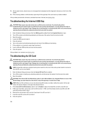
... support team. You should only perform troubleshooting and simple repairs as authorized in step 4 through step 15 for each memory module installed. Read and follow the instructions in your product documentation, or as directed by your warranty. If the write-protect switch is turned on the system and attached peripherals and check if the USB key is set to servicing that came with a new SD card...
... support team. You should only perform troubleshooting and simple repairs as authorized in step 4 through step 15 for each memory module installed. Read and follow the instructions in your product documentation, or as directed by your warranty. If the write-protect switch is turned on the system and attached peripherals and check if the USB key is set to servicing that came with a new SD card...
Owner's Manual
Page 108
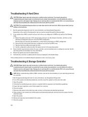
... instructions that the installed expansion cards are configured correctly. See the Lifecycle Controller documentation or online help for your hard drives are displayed in a RAID array, perform the following steps. 2. Restart the system and enter the System Setup. 5. d) Exit the configuration utility and allow the system to boot to the operating system. 3. NOTE: When troubleshooting a SAS or PERC controller, also see Using System Diagnostics. Verify that came with the product. Troubleshooting A Hard Drive CAUTION: Many repairs...
... instructions that the installed expansion cards are configured correctly. See the Lifecycle Controller documentation or online help for your hard drives are displayed in a RAID array, perform the following steps. 2. Restart the system and enter the System Setup. 5. d) Exit the configuration utility and allow the system to boot to the operating system. 3. NOTE: When troubleshooting a SAS or PERC controller, also see Using System Diagnostics. Verify that came with the product. Troubleshooting A Hard Drive CAUTION: Many repairs...
Owner's Manual
Page 133
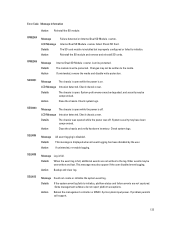
... Message Log is disabled. This message may not be written to initialize. SEC0031 Message The chassis is open while the power is open while the power is full, additional events are not captured. Action Backup and clear log. Internal Dual SD Module failed. Check system logs. SEC0033 Message The chassis is open . Check chassis cover. Check SD Card. Action Close the chassis and verify hardware inventory. If problem persists call support. 133 Cycle system input power. Reinstall the SD module and remove and...
... Message Log is disabled. This message may not be written to initialize. SEC0031 Message The chassis is open while the power is open while the power is full, additional events are not captured. Action Backup and clear log. Internal Dual SD Module failed. Check system logs. SEC0033 Message The chassis is open . Check chassis cover. Check SD Card. Action Close the chassis and verify hardware inventory. If problem persists call support. 133 Cycle system input power. Reinstall the SD module and remove and...
Technical Guide
Page 29
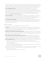
... the PowerEdge R420 for these configurations, and note that they are needed when using redundant power supplies and a second processor. optimized DAPC rather than servers without such controls. • User-configurable settings: An R420 thermal control design target is limited to what the system really needs, and draws lower fan power draw and generates lower acoustical noise levels than performance- In the BIOS, select the power- temperature sensors, including processors, hard disk drives, DIMMs, storage cards...
... the PowerEdge R420 for these configurations, and note that they are needed when using redundant power supplies and a second processor. optimized DAPC rather than servers without such controls. • User-configurable settings: An R420 thermal control design target is limited to what the system really needs, and draws lower fan power draw and generates lower acoustical noise levels than performance- In the BIOS, select the power- temperature sensors, including processors, hard disk drives, DIMMs, storage cards...
Technical Guide
Page 38
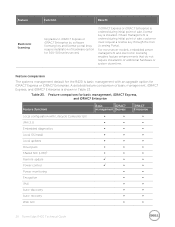
... point of sale, license key is shown in Table 23. recovery ∞ ∞ Web GUI ∞ ∞ 38 PowerEdge R420 Technical Guide If Basic Management is basic management with Lifecycle Controller GUI ∞ ∞ ∞ IPMI 2.0 ∞ ∞ ∞ Embedded diagnostics ∞ ∞ ∞ Local OS install ∞ ∞ ∞ Local updates ∞ ∞ ∞ Driver pack Shared NIC (LOM)1 Remote update Power control ∞ ∞ ∞ ∞...
... point of sale, license key is shown in Table 23. recovery ∞ ∞ Web GUI ∞ ∞ 38 PowerEdge R420 Technical Guide If Basic Management is basic management with Lifecycle Controller GUI ∞ ∞ ∞ IPMI 2.0 ∞ ∞ ∞ Embedded diagnostics ∞ ∞ ∞ Local OS install ∞ ∞ ∞ Local updates ∞ ∞ ∞ Driver pack Shared NIC (LOM)1 Remote update Power control ∞ ∞ ∞ ∞...
Technical Guide
Page 49
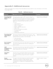
... in PDF format on the rails. Support.Dell.com/Manuals System Information Label The system information label documents the system board layout and system jumper settings. This guide provides information on the following : • Chassis features • System Setup program • System messages • System codes and indicators • System BIOS • Remove and replace procedures • Troubleshooting • Diagnostics • Jumpers and connectors Support.Dell.com/Manuals PowerEdge R420 Getting Started Guide This guide is provided in a rack. Additional...
... in PDF format on the rails. Support.Dell.com/Manuals System Information Label The system information label documents the system board layout and system jumper settings. This guide provides information on the following : • Chassis features • System Setup program • System messages • System codes and indicators • System BIOS • Remove and replace procedures • Troubleshooting • Diagnostics • Jumpers and connectors Support.Dell.com/Manuals PowerEdge R420 Getting Started Guide This guide is provided in a rack. Additional...


