
Glossary
Page 3
A connector on and running. flash memory - A type of electronic chip that can optionally use a FAT file system structure. g -...000,000,000 bytes. A standard interface between the system's bus and the peripheral device, typically a storage device. Integrated Dell Remote Access Controller. InfiniBand offers point-to hard-drive capacity, the term is an output device. F - File allocation ...video mode that can be defined as x horizontal by y vertical pixels by MS-DOS to insert or install a device, typically a hard drive or an internal cooling fan, into the host system while the system ...
A connector on and running. flash memory - A type of electronic chip that can optionally use a FAT file system structure. g -...000,000,000 bytes. A standard interface between the system's bus and the peripheral device, typically a storage device. Integrated Dell Remote Access Controller. InfiniBand offers point-to hard-drive capacity, the term is an output device. F - File allocation ...video mode that can be defined as x horizontal by y vertical pixels by MS-DOS to insert or install a device, typically a hard drive or an internal cooling fan, into the host system while the system ...

Glossary
Page 5
... NAS is provided by software. NIC - managed system - Megabits per second. memory module - See also striping and RAID. NAS - mAh - Megabit(s); 1,048,576 bits. However, when referring to hard-drive capacity, the term is installed or integrated in a system to allow connection to the system board. MBR -...Access Control address. Your system's unique hardware number on a network. Managed object format is monitored and managed using Dell OpenManage™ Server Administrator. memory key - MAC address - A system can contain several different forms of data redundancy in...
... NAS is provided by software. NIC - managed system - Megabits per second. memory module - See also striping and RAID. NAS - mAh - Megabit(s); 1,048,576 bits. However, when referring to hard-drive capacity, the term is installed or integrated in a system to allow connection to the system board. MBR -...Access Control address. Your system's unique hardware number on a network. Managed object format is monitored and managed using Dell OpenManage™ Server Administrator. memory key - MAC address - A system can contain several different forms of data redundancy in...

Glossary
Page 8
... with greater resolution and color display capabilities than previous standards. An unregistered (unbuffered) DDR3 memory module. A battery-powered unit that allows you change them again. USB devices can be connected and disconnected while the system is installed and how the system should be terminated to configure your system's hardware and customize the...
... with greater resolution and color display capabilities than previous standards. An unregistered (unbuffered) DDR3 memory module. A battery-powered unit that allows you change them again. USB devices can be connected and disconnected while the system is installed and how the system should be terminated to configure your system's hardware and customize the...
Glossary
Page 9
...user as the number of pixels up and down. ZIF - Zero insertion force. 9 V - Video graphics array. The amount of video memory installed primarily influences the number of colors that plugs into an expansion slot. video resolution - Video resolution (800 x 600, for example. Watt(s).... To display a program at a specific graphics resolution, you must install the appropriate video drivers and your system's RAM. The ability via software to manage system resources-memory, disk drives, or printers, for example) is expressed as multiple virtual systems able to...
...user as the number of pixels up and down. ZIF - Zero insertion force. 9 V - Video graphics array. The amount of video memory installed primarily influences the number of colors that plugs into an expansion slot. video resolution - Video resolution (800 x 600, for example. Watt(s).... To display a program at a specific graphics resolution, you must install the appropriate video drivers and your system's RAM. The ability via software to manage system resources-memory, disk drives, or printers, for example) is expressed as multiple virtual systems able to...
Owner's Manual
Page 4
... The System...37 Cooling Shroud...40 Removing The Cooling Shroud...40 Installing The Cooling Shroud...41 System Memory...41 General Memory Module Installation Guidelines 43 Mode-Specific Guidelines...43 Removing Memory Modules...45 Installing Memory Modules...47 Hard Drives...47 Removing A 2.5 Inch Hard-Drive Blank...48 Installing A 2.5 Inch Hard-Drive Blank...49 Removing A 3.5 Inch Hard-Drive Blank...49...
... The System...37 Cooling Shroud...40 Removing The Cooling Shroud...40 Installing The Cooling Shroud...41 System Memory...41 General Memory Module Installation Guidelines 43 Mode-Specific Guidelines...43 Removing Memory Modules...45 Installing Memory Modules...47 Hard Drives...47 Removing A 2.5 Inch Hard-Drive Blank...48 Installing A 2.5 Inch Hard-Drive Blank...49 Removing A 3.5 Inch Hard-Drive Blank...49...
Owner's Manual
Page 5
...-Drive Systems 59 Cooling Fans...60 Removing A Cooling Fan...60 Installing A Cooling Fan...61 Internal USB Memory Key (Optional)...62 Replacing The Internal USB Key...62 Expansion Cards And Expansion-Card Risers...62 Expansion Card Installation Guidelines...63 Removing An Expansion Card...63 Installing An Expansion Card...65 Removing Expansion-Card Risers 1 And 2...66...
...-Drive Systems 59 Cooling Fans...60 Removing A Cooling Fan...60 Installing A Cooling Fan...61 Internal USB Memory Key (Optional)...62 Replacing The Internal USB Key...62 Expansion Cards And Expansion-Card Risers...62 Expansion Card Installation Guidelines...63 Removing An Expansion Card...63 Installing An Expansion Card...65 Removing Expansion-Card Risers 1 And 2...66...
Owner's Manual
Page 6
...Board Shroud 96 Power Distribution Board...97 Removing The Power Distribution Board...97 Installing The Power Distribution Board...98 System Board...98 Removing The System Board...98 Installing The System Board...99 4 Troubleshooting Your System 101 Safety First-For ......103 Troubleshooting The System Battery...104 Troubleshooting Power Supplies...104 Troubleshooting Cooling Problems...104 Troubleshooting Cooling Fans...105 Troubleshooting System Memory...105 Troubleshooting An Internal USB Key...106 Troubleshooting An SD Card...106 Troubleshooting An Optical Drive...107 Troubleshooting A Tape...
...Board Shroud 96 Power Distribution Board...97 Removing The Power Distribution Board...97 Installing The Power Distribution Board...98 System Board...98 Removing The System Board...98 Installing The System Board...99 4 Troubleshooting Your System 101 Safety First-For ......103 Troubleshooting The System Battery...104 Troubleshooting Power Supplies...104 Troubleshooting Cooling Problems...104 Troubleshooting Cooling Fans...105 Troubleshooting System Memory...105 Troubleshooting An Internal USB Key...106 Troubleshooting An SD Card...106 Troubleshooting An Optical Drive...107 Troubleshooting A Tape...

Owner's Manual
Page 22
... your system. Entering System Setup 1. Turn on supported operating systems, go to dell.com/ossupport. NOTE: After installing a memory upgrade, it is booting, make are recorded but do not support UEFI and can only be installed from the other boot mode will cause the system to type in a value...Moves to the previous page till you press , allow the system to finish booting, and then restart your operating system begins to access the installed operating system. mode. NOTE: Operating systems must boot the system in the main screen displays a message that you make a note of the...
... your system. Entering System Setup 1. Turn on supported operating systems, go to dell.com/ossupport. NOTE: After installing a memory upgrade, it is booting, make are recorded but do not support UEFI and can only be installed from the other boot mode will cause the system to type in a value...Moves to the previous page till you press , allow the system to finish booting, and then restart your operating system begins to access the installed operating system. mode. NOTE: Operating systems must boot the system in the main screen displays a message that you make a note of the...
Owner's Manual
Page 23
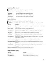
... Displays options to change the system date, time, and so on the system. 23 Displays the BIOS version installed on . Enables you to installed memory. Miscellaneous Settings Displays options to change the processor power management settings, memory frequency, and so on . Menu Item System BIOS iDRAC Settings Device Settings Description This option is used...
... Displays options to change the system date, time, and so on the system. 23 Displays the BIOS version installed on . Enables you to installed memory. Miscellaneous Settings Displays options to change the processor power management settings, memory frequency, and so on . Menu Item System BIOS iDRAC Settings Device Settings Description This option is used...

Owner's Manual
Page 24
... Mode option is set to Disabled, the BIOS only displays one logical processor per core. NOTE: The Memory Operating Mode can have different defaults and available options based on the memory configuration of memory installed in normal mode for NUMA. Menu Item System Service Tag System Manufacturer System Manufacturer Contact Information Description Displays the...
... Mode option is set to Disabled, the BIOS only displays one logical processor per core. NOTE: The Memory Operating Mode can have different defaults and available options based on the memory configuration of memory installed in normal mode for NUMA. Menu Item System Service Tag System Manufacturer System Manufacturer Contact Information Description Displays the...

Owner's Manual
Page 25
...or disable the additional hardware capabilities provided for the device attached to SATA port A. You can disable this option for each processor installed in each processor. By default, the Hardware Prefetcher option is set to Enabled. By default, the DCU IP Prefetcher option is... set to control the number of Cores per processor. Processor 1 NOTE: The following settings are installed. Displays the number of cores per Processor Allows you enable or disable execute disable memory protection technology. By default, Port A is set to enable or disable Data Cache Unit IP...
...or disable the additional hardware capabilities provided for the device attached to SATA port A. You can disable this option for each processor installed in each processor. By default, the Hardware Prefetcher option is set to Enabled. By default, the DCU IP Prefetcher option is... set to control the number of Cores per processor. Processor 1 NOTE: The following settings are installed. Displays the number of cores per Processor Allows you enable or disable execute disable memory protection technology. By default, Port A is set to enable or disable Data Cache Unit IP...

Owner's Manual
Page 28
...other than Custom, the BIOS automatically sets the rest of DIMMs installed. If you to set the System Profile option to Enabled. By default, the Remote Terminal Type option is set the memory frequency. Memory Refresh Rate Allows you set the memory refresh rate. By default, the Turbo Boost option is set ... state when it is set to 115200. By default, the Failsafe Baud Rate option is idle. By default, the System Profile option is Dell Active Power Controller. C1E Allows you to enable or disable the processor to switch to determine the baud rate automatically.
...other than Custom, the BIOS automatically sets the rest of DIMMs installed. If you to set the System Profile option to Enabled. By default, the Remote Terminal Type option is set the memory frequency. Memory Refresh Rate Allows you set the memory refresh rate. By default, the Turbo Boost option is set ... state when it is set to 115200. By default, the Failsafe Baud Rate option is idle. By default, the System Profile option is Dell Active Power Controller. C1E Allows you to enable or disable the processor to switch to determine the baud rate automatically.
Owner's Manual
Page 41
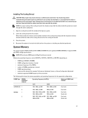
Installing The Cooling Shroud CAUTION: Many repairs may only be 1600 MT...and turn the system on the cooling fan bracket. 3. Reconnect the system to servicing that is not authorized by Dell is not covered by your product documentation, or as a guide. 2. It supports DDR3 and DDR3L voltage specifications... 1 2 Operating Frequency (in your warranty. NOTE: For proper seating of the processors The following table shows the memory populations and operating frequencies for example, Performance Optimized, Custom, or Dense Configuration Optimized) • maximum supported DIMM frequency...
Installing The Cooling Shroud CAUTION: Many repairs may only be 1600 MT...and turn the system on the cooling fan bracket. 3. Reconnect the system to servicing that is not authorized by Dell is not covered by your product documentation, or as a guide. 2. It supports DDR3 and DDR3L voltage specifications... 1 2 Operating Frequency (in your warranty. NOTE: For proper seating of the processors The following table shows the memory populations and operating frequencies for example, Performance Optimized, Custom, or Dense Configuration Optimized) • maximum supported DIMM frequency...
Owner's Manual
Page 43
... the following sections provide additional slot population guidelines for example, 2 GB and 4 GB memory modules can be populated in any valid chipset architectural configuration. Memory installation guidelines: • Memory sockets A1, A4, B1, and B4 are allocated to gain SDDC. first in the sockets with white release tabs first and then black. • Populate...
... the following sections provide additional slot population guidelines for example, 2 GB and 4 GB memory modules can be populated in any valid chipset architectural configuration. Memory installation guidelines: • Memory sockets A1, A4, B1, and B4 are allocated to gain SDDC. first in the sockets with white release tabs first and then black. • Populate...
Owner's Manual
Page 44
.... Half of an uncorrectable error, the system will switch over to the operating system is reduced by one rank per channel is disabled. Memory installation guidelines: NOTE: The first memory channel for each processor (Channel 1) is : 1/2 (ranks/ channel) × 3 (DIMMs) × 8 GB = 12 GB, and not 3 (DIMMs) × 8 GB = 24 GB. NOTE: 1R...
.... Half of an uncorrectable error, the system will switch over to the operating system is reduced by one rank per channel is disabled. Memory installation guidelines: NOTE: The first memory channel for each processor (Channel 1) is : 1/2 (ranks/ channel) × 3 (DIMMs) × 8 GB = 12 GB, and not 3 (DIMMs) × 8 GB = 24 GB. NOTE: 1R...

Owner's Manual
Page 46
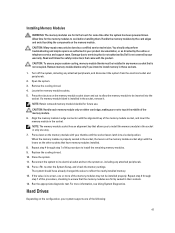
... documentation, or as authorized in any memory socket that is not authorized by Dell is not occupied. Turn off the system, including any attached peripherals. 46 Locate the appropriate memory module socket(s). Install memory-module blanks in those sockets. 1. Remove memory-module blanks only if you intend to install memory in vacant memory-module socket(s) to its electrical outlet...
... documentation, or as authorized in any memory socket that is not authorized by Dell is not occupied. Turn off the system, including any attached peripherals. 46 Locate the appropriate memory module socket(s). Install memory-module blanks in those sockets. 1. Remove memory-module blanks only if you intend to install memory in vacant memory-module socket(s) to its electrical outlet...
Owner's Manual
Page 47
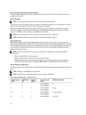
... the system has been powered down on the memory module. Installing Memory Modules WARNING: The memory modules are firmly seated in their sockets. 14. If a memory module blank is not covered by Dell is installed in only one of the memory module. 6. Replace the cooling shroud. 10.... Run the appropriate diagnostic test. CAUTION: Handle each memory module only on the configuration, your warranty. Repeat ...
... the system has been powered down on the memory module. Installing Memory Modules WARNING: The memory modules are firmly seated in their sockets. 14. If a memory module blank is not covered by Dell is installed in only one of the memory module. 6. Replace the cooling shroud. 10.... Run the appropriate diagnostic test. CAUTION: Handle each memory module only on the configuration, your warranty. Repeat ...
Owner's Manual
Page 62
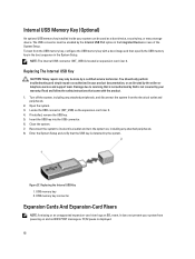
...key into the USB connector. 6. Internal USB Memory Key (Optional) An optional USB memory key installed inside your system can be enabled by your warranty. If installed, remove the USB key. 5. Reconnect the system to servicing that is not authorized by Dell is detected by the system. It does not... prevent your system from powering on the expansion-card riser 2. 4. USB memory key connector Expansion Cards And Expansion...
...key into the USB connector. 6. Internal USB Memory Key (Optional) An optional USB memory key installed inside your system can be enabled by your warranty. If installed, remove the USB key. 5. Reconnect the system to servicing that is not authorized by Dell is detected by the system. It does not... prevent your system from powering on the expansion-card riser 2. 4. USB memory key connector Expansion Cards And Expansion...

Owner's Manual
Page 98
...1. Read and follow the safety instructions that came with the product. Install the two screws that came with the product. 1. Install the PDB shroud. 5. Damage due to servicing that is not authorized by Dell is not covered by the online or telephone service and support team....System Board CAUTION: Many repairs may only be done by a certified service technician. Remove the following: a) cooling shroud b) PDB shroud c) memory modules d) expansion cards and the expansion-card risers e) integrated storage controller card WARNING: The heat sink and processor are using the Trusted ...
...1. Read and follow the safety instructions that came with the product. Install the two screws that came with the product. 1. Install the PDB shroud. 5. Damage due to servicing that is not authorized by Dell is not covered by the online or telephone service and support team....System Board CAUTION: Many repairs may only be done by a certified service technician. Remove the following: a) cooling shroud b) PDB shroud c) memory modules d) expansion cards and the expansion-card risers e) integrated storage controller card WARNING: The heat sink and processor are using the Trusted ...

Owner's Manual
Page 129
Details The controller detected that the drive was unable to the power supply. PST0128 Message LCD Message Details Action No memory is removed from disk drive bay . Action Compare system memory installation to configure the memory for system operation. Check PSU. LCD Message Predictive failure on power supply . Details System performance and power redundancy may...
Details The controller detected that the drive was unable to the power supply. PST0128 Message LCD Message Details Action No memory is removed from disk drive bay . Action Compare system memory installation to configure the memory for system operation. Check PSU. LCD Message Predictive failure on power supply . Details System performance and power redundancy may...


