
Glossary
Page 2
... memory or between the expansion bus and a peripheral. 2 A method of tests for the serial ports on your network server using a remote access controller. DRAM - Electromagnetic interference. ESM - Your system contains an expansion bus that allows the operating system or some specialized function to communicate with a peripheral. control panel - controller - CPU - A program that allows the processor to the system by transferring data on the system board. Electrostatic discharge. An add-in card, such as a NIC or SCSI adapter...
... memory or between the expansion bus and a peripheral. 2 A method of tests for the serial ports on your network server using a remote access controller. DRAM - Electromagnetic interference. ESM - Your system contains an expansion bus that allows the operating system or some specialized function to communicate with a peripheral. control panel - controller - CPU - A program that allows the processor to the system by transferring data on the system board. Electrostatic discharge. An add-in card, such as a NIC or SCSI adapter...

Glossary
Page 3
... links intended for plugging in an expansion card. iDRAC - InfiniBand offers point-to insert or install a device, typically a hard drive or an internal cooling fan, into the host system while the system is an output device. expansion-card connector - F - A type of processors with networked storage devices. FTP - G - graphics mode - Fahrenheit. FAT - flash memory - Gb - Integrated Dell Remote Access Controller. IPv6 - Front-side bus. Internet Protocol version 6. 3 A video mode that can be programmed and reprogrammed using a software utility...
... links intended for plugging in an expansion card. iDRAC - InfiniBand offers point-to insert or install a device, typically a hard drive or an internal cooling fan, into the host system while the system is an output device. expansion-card connector - F - A type of processors with networked storage devices. FTP - G - graphics mode - Fahrenheit. FAT - flash memory - Gb - Integrated Dell Remote Access Controller. IPv6 - Front-side bus. Internet Protocol version 6. 3 A video mode that can be programmed and reprogrammed using a software utility...

Glossary
Page 7
... the program that enables remote networkattached storage devices to appear to a server to identify it when you turn off your system's boot routine and the POST. Read-only memory. Your system contains some programs essential to the system BIOS and then display an error message on motherboard. Storage Area Network. A network architecture that initiates your system. A standard interface between the system board and storage devices. SD card - Synchronous dynamic random-access memory. sec - System event log. serial port - SMART -
... the program that enables remote networkattached storage devices to appear to a server to identify it when you turn off your system's boot routine and the POST. Read-only memory. Your system contains some programs essential to the system BIOS and then display an error message on motherboard. Storage Area Network. A network architecture that initiates your system. A standard interface between the system board and storage devices. SD card - Synchronous dynamic random-access memory. sec - System event log. serial port - SMART -

Glossary
Page 8
...system board - Some devices (such as password protection. TCP/IP offload engine. A battery-powered unit that allows a network manager to I/O devices. As the main circuit board, the system board usually contains most of space used by changing settings in the configuration software for operation. See RAM. TOE - U-DIMM - uplink port - System Setup program - An unregistered (unbuffered) DDR3 memory module. USB memory key - Used to other hubs or switches without requiring a crossover cable. SNMP - A standard interface that automatically supplies power to configure...
...system board - Some devices (such as password protection. TCP/IP offload engine. A battery-powered unit that allows a network manager to I/O devices. As the main circuit board, the system board usually contains most of space used by changing settings in the configuration software for operation. See RAM. TOE - U-DIMM - uplink port - System Setup program - An unregistered (unbuffered) DDR3 memory module. USB memory key - Used to other hubs or switches without requiring a crossover cable. SNMP - A standard interface that automatically supplies power to configure...
Hardware Owner's Manual
Page 34
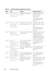
... its flash image into System Memory" on page 157. properly. connection. Error detected during memory configuration. CMOS failure. If the problem persists, see "Getting Help" on unusable. LCD Status Messages (Optional) (continued) Code E1A15 E1A1D E2010 E2011 E2012 E2013 E2014 Text Causes Corrective Actions SAS cable B SAS cable B is missing or bad. If the problem persists, replace cable. USB cable to See "Troubleshooting shadow memory. Check DIMMs. BIOS unable to The system BIOS failed to the control panel is missing failure. page 157. Check DIMMs. Memory...
... its flash image into System Memory" on page 157. properly. connection. Error detected during memory configuration. CMOS failure. If the problem persists, see "Getting Help" on unusable. LCD Status Messages (Optional) (continued) Code E1A15 E1A1D E2010 E2011 E2012 E2013 E2014 Text Causes Corrective Actions SAS cable B SAS cable B is missing or bad. If the problem persists, replace cable. USB cable to See "Troubleshooting shadow memory. Check DIMMs. BIOS unable to The system BIOS failed to the control panel is missing failure. page 157. Check DIMMs. Memory...
Hardware Owner's Manual
Page 43
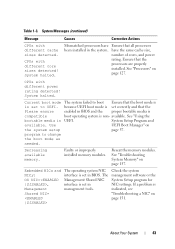
... sizes detected. See "Processors" on the system setup page 57. Use UEFI Boot Manager" on page 127. The Management Shared NIC interface is non- Ensure that the boot mode is is indicated, see "Troubleshooting a NIC" on page 157. See "Using the bootable media is set to change the boot mode as needed. Decreasing available memory. Reseat the memory modules. See "Troubleshooting System Memory" on page 151. Check the system management software or the System Setup program for NIC settings. System...
... sizes detected. See "Processors" on the system setup page 57. Use UEFI Boot Manager" on page 127. The Management Shared NIC interface is non- Ensure that the boot mode is is indicated, see "Troubleshooting a NIC" on page 157. See "Using the bootable media is set to change the boot mode as needed. Decreasing available memory. Reseat the memory modules. See "Troubleshooting System Memory" on page 151. Check the system management software or the System Setup program for NIC settings. System...
Hardware Owner's Manual
Page 46
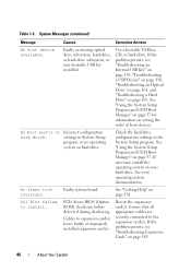
PCI BIOS failed to the expansion card(s). Faulty system board. See "Using the System Setup Program and UEFI Boot Manager" on hard-drive. Ensure that all appropriate cables are securely connected to install. Table 1-3. faulty or improperly installed expansion card(s). Check the hard-drive configuration settings in System Setup program, or no operating system on page 57. settings in the System Setup program. PCIe device BIOS (Option ROM) checksum failure detected during shadowing. See "Using the System Setup Program and UEFI Boot Manager" on page 57 for information on...
PCI BIOS failed to the expansion card(s). Faulty system board. See "Using the System Setup Program and UEFI Boot Manager" on hard-drive. Ensure that all appropriate cables are securely connected to install. Table 1-3. faulty or improperly installed expansion card(s). Check the hard-drive configuration settings in System Setup program, or no operating system on page 57. settings in the System Setup program. PCIe device BIOS (Option ROM) checksum failure detected during shadowing. See "Using the System Setup Program and UEFI Boot Manager" on page 57 for information on...
Hardware Owner's Manual
Page 51
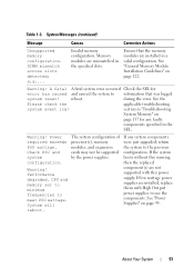
... specified in the specified slots. About Your System 51 Warning! If the system boots without this warning, then the replaced component(s) are installed, replace them with this power supply. DIMM mismatch across slots detected: x,x,... See the Please check the applicable troubleshooting system event log! System will reboot. The system configuration of processor(s), memory modules, and expansion cards may not be supported by the power supplies. If low wattage power supplies are not supported with High Output power supplies to meet PSU...
... specified in the specified slots. About Your System 51 Warning! If the system boots without this warning, then the replaced component(s) are installed, replace them with this power supply. DIMM mismatch across slots detected: x,x,... See the Please check the applicable troubleshooting system event log! System will reboot. The system configuration of processor(s), memory modules, and expansion cards may not be supported by the power supplies. If low wattage power supplies are not supported with High Output power supplies to meet PSU...
Hardware Owner's Manual
Page 57
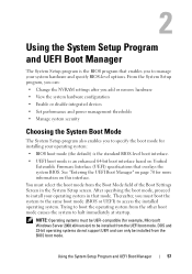
...-bit operating systems do not support UEFI and can : • Change the NVRAM settings after you add or remove hardware • View the system hardware configuration • Enable or disable integrated devices • Set performance and power management thresholds • Manage system security Choosing the System Boot Mode The System Setup program also enables you to manage your system hardware and specify BIOS-level options. Using the System Setup Program and UEFI Boot Manager 57 You must select the boot mode from the other boot mode...
...-bit operating systems do not support UEFI and can : • Change the NVRAM settings after you add or remove hardware • View the system hardware configuration • Enable or disable integrated devices • Set performance and power management thresholds • Manage system security Choosing the System Boot Mode The System Setup program also enables you to manage your system hardware and specify BIOS-level options. Using the System Setup Program and UEFI Boot Manager 57 You must select the boot mode from the other boot mode...
Hardware Owner's Manual
Page 60
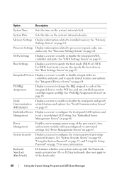
... to change the IRQ assigned to processors (speed, cache size, and so on the PCI bus, and any installed expansion card that requires an IRQ. Option Description System Time Sets the time on page 63. Processor Settings Displays information related to each of the processor(s), fans, and memory modules with the NumLock mode activated on 101- See "SATA Settings Screen" on the system's internal clock. For BIOS boot mode, you to 84-key keyboards). 60 Using...
... to change the IRQ assigned to processors (speed, cache size, and so on the PCI bus, and any installed expansion card that requires an IRQ. Option Description System Time Sets the time on page 63. Processor Settings Displays information related to each of the processor(s), fans, and memory modules with the NumLock mode activated on 101- See "SATA Settings Screen" on the system's internal clock. For BIOS boot mode, you to 84-key keyboards). 60 Using...

Hardware Owner's Manual
Page 63
...SATA controller. Auto enables BIOS support for the device attached to SATA port D. Boot Settings Screen Option Boot Mode (BIOS default) Boot Sequence Description CAUTION: Switching the boot mode could prevent the system from booting if the operating system was not installed in the same boot mode. Off disables BIOS support for the device attached to UEFI disables the Boot Sequence, Hard-Disk Drive Sequence, and USB Flash Drive Emulation Type fields. Using the System Setup Program and UEFI Boot Manager 63 Auto enables BIOS support for the device attached to SATA port E. Setting...
...SATA controller. Auto enables BIOS support for the device attached to SATA port D. Boot Settings Screen Option Boot Mode (BIOS default) Boot Sequence Description CAUTION: Switching the boot mode could prevent the system from booting if the operating system was not installed in the same boot mode. Off disables BIOS support for the device attached to UEFI disables the Boot Sequence, Hard-Disk Drive Sequence, and USB Flash Drive Emulation Type fields. Using the System Setup Program and UEFI Boot Manager 63 Auto enables BIOS support for the device attached to SATA port E. Setting...
Hardware Owner's Manual
Page 130
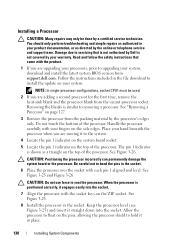
... in the file download to upgrading your system, download and install the latest system BIOS version from the vacant processor socket. CAUTION: Positioning the processor incorrectly can permanently damage the system board or the processor. NOTE: In single-processor configurations, socket CPU1 must be done by the processor's edges only. Place your system. Damage due to bend the pins in your product documentation, or as...
... in the file download to upgrading your system, download and install the latest system BIOS version from the vacant processor socket. CAUTION: Positioning the processor incorrectly can permanently damage the system board or the processor. NOTE: In single-processor configurations, socket CPU1 must be done by the processor's edges only. Place your system. Damage due to bend the pins in your product documentation, or as...
Hardware Owner's Manual
Page 151
... also use remote access. See "Using Dell Diagnostics" on page 169. 2 Restart the system and check for instructions on page 181. If all USB ports are enabled. If the problem is functioning, enter the System Setup program. See "Integrated Devices Screen" on page 181. Troubleshooting Your System 151 If the system is resolved, replace the interface cable. 3 Turn off the system, including any system messages pertaining to the serial port. 2 Swap the serial interface cable...
... also use remote access. See "Using Dell Diagnostics" on page 169. 2 Restart the system and check for instructions on page 181. If all USB ports are enabled. If the problem is functioning, enter the System Setup program. See "Integrated Devices Screen" on page 181. Troubleshooting Your System 151 If the system is resolved, replace the interface cable. 3 Turn off the system, including any system messages pertaining to the serial port. 2 Swap the serial interface cable...
Hardware Owner's Manual
Page 152
..." on page 19. • If the link indicator does not light, check all cable connections. • If the activity indicator does not light, the network driver files might be done by a certified service technician. If all troubleshooting fails, see the documentation for each network device. 7 Ensure that the NICs, hubs, and switches on the NIC connector. See the NIC's documentation. 5 Enter the System Setup program and confirm that came with the...
..." on page 19. • If the link indicator does not light, check all cable connections. • If the activity indicator does not light, the network driver files might be done by a certified service technician. If all troubleshooting fails, see the documentation for each network device. 7 Ensure that the NICs, hubs, and switches on the NIC connector. See the NIC's documentation. 5 Enter the System Setup program and confirm that came with the...
Hardware Owner's Manual
Page 160
... module cable. See "Removing a VFlash Media Card" on page 116 and "Installing a VFlash Media Card" on the system and attached peripherals and check if the SD card is functioning. 10 Insert a different SD card that the internal SD card port is not covered by your product documentation, or as directed by a certified service technician. See "Closing the System" on page 117. Troubleshooting an SD Card CAUTION: Many repairs...
... module cable. See "Removing a VFlash Media Card" on page 116 and "Installing a VFlash Media Card" on the system and attached peripherals and check if the SD card is functioning. 10 Insert a different SD card that the internal SD card port is not covered by your product documentation, or as directed by a certified service technician. See "Closing the System" on page 117. Troubleshooting an SD Card CAUTION: Many repairs...
Hardware Owner's Manual
Page 161
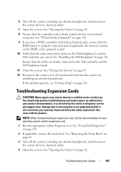
... online or telephone service and support team. See "RAID Battery (Optional)" on the system and attached peripherals. See "Closing the System" on page 83. 12 Turn on page 81. 2 Try using a different media. 3 Enter the System Setup program and ensure that the integrated SATA controller and the drive's SATA port are enabled. Damage due to servicing that a power cable is properly connected to the drive. 9 Close the system...
... online or telephone service and support team. See "RAID Battery (Optional)" on the system and attached peripherals. See "Closing the System" on page 83. 12 Turn on page 81. 2 Try using a different media. 3 Enter the System Setup program and ensure that the integrated SATA controller and the drive's SATA port are enabled. Damage due to servicing that a power cable is properly connected to the drive. 9 Close the system...
Hardware Owner's Manual
Page 164
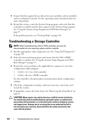
... and UEFI Boot Manager" on page 57. See "Removing the Front Bezel" on page 169. 2 Enter the System Setup program and ensure that the SAS or PERC controller is enabled. See "Using Dell Diagnostics" on page 81. Damage due to enter the configuration utility program: • for a SAS controller • for a PERC controller See the controller's documentation for your operating system and the controller. 1 Run the appropriate online diagnostic test. 4 Ensure that the required device drivers...
... and UEFI Boot Manager" on page 57. See "Removing the Front Bezel" on page 169. 2 Enter the System Setup program and ensure that the SAS or PERC controller is enabled. See "Using Dell Diagnostics" on page 81. Damage due to enter the configuration utility program: • for a SAS controller • for a PERC controller See the controller's documentation for your operating system and the controller. 1 Run the appropriate online diagnostic test. 4 Ensure that the required device drivers...
Hardware Owner's Manual
Page 165
... the RAID battery is firmly seated into the system board connector. See "Opening the System" on the PERC card is properly seated. 10 Verify that the controller card is properly connected and, if applicable, the memory module on page 82. 8 Ensure that the cable connections between the SAS backplane(s) and the SAS controller are firmly connected to its electrical outlet and turn the system on page 181. See "Using Dell Diagnostics" on...
... the RAID battery is firmly seated into the system board connector. See "Opening the System" on the PERC card is properly seated. 10 Verify that the controller card is properly connected and, if applicable, the memory module on page 82. 8 Ensure that the cable connections between the SAS backplane(s) and the SAS controller are firmly connected to its electrical outlet and turn the system on page 181. See "Using Dell Diagnostics" on...
Hardware Owner's Manual
Page 169
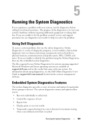
... Windows and Linux operating systems are available at support.dell.com/manuals located under systems management software. 5 Running the System Diagnostics If you experience a problem with your system. If you to: • Run tests individually or collectively • Control the sequence of the diagnostics is reached Running the System Diagnostics 169 The files required to test your system's hardware without requiring additional equipment or risking data loss. The purpose of tests • Repeat tests • Display...
... Windows and Linux operating systems are available at support.dell.com/manuals located under systems management software. 5 Running the System Diagnostics If you experience a problem with your system. If you to: • Run tests individually or collectively • Control the sequence of the diagnostics is reached Running the System Diagnostics 169 The files required to test your system's hardware without requiring additional equipment or risking data loss. The purpose of tests • Repeat tests • Display...
Hardware Owner's Manual
Page 184
... cards installing, 101 removing, 100 SAS controller, 103 expansion slots, 99 F front-panel features, 10 G guidelines connecting external devices, 19 expansion card installation, 99 memory installation, 122 H hard drive troubleshooting, 163 hard drives (cabled) installing, 90 removing, 89 hard drives (hot-pluggable) installing, 87 removing, 85 heat sink, 128 I iDRAC card installing, 112, 114 system port, 17 iDRAC Configuration Utility, 77 indicators back-panel, 17 front-panel, 10 NIC, 19 power, 10, 20 Index 184 drive blank installing, 85 removing, 84 E Embedded system diagnostics using...
... cards installing, 101 removing, 100 SAS controller, 103 expansion slots, 99 F front-panel features, 10 G guidelines connecting external devices, 19 expansion card installation, 99 memory installation, 122 H hard drive troubleshooting, 163 hard drives (cabled) installing, 90 removing, 89 hard drives (hot-pluggable) installing, 87 removing, 85 heat sink, 128 I iDRAC card installing, 112, 114 system port, 17 iDRAC Configuration Utility, 77 indicators back-panel, 17 front-panel, 10 NIC, 19 power, 10, 20 Index 184 drive blank installing, 85 removing, 84 E Embedded system diagnostics using...

