
Glossary
Page 7
...some programs essential to the system BIOS and then display an error message on motherboard. SCSI - SD card - serial port - Redundant array of providing data redundancy. Some common implementations of code in RAM is most often used to identify it when you... standard interface between the system board and storage devices. Small computer system interface. An I /O port with a 9-pin connector that you call Dell for program instructions and data. SDRAM - Synchronous dynamic random-access memory. SEL - System event log. service tag - SMART - Self-Monitoring ...
...some programs essential to the system BIOS and then display an error message on motherboard. SCSI - SD card - serial port - Redundant array of providing data redundancy. Some common implementations of code in RAM is most often used to identify it when you... standard interface between the system board and storage devices. Small computer system interface. An I /O port with a 9-pin connector that you call Dell for program instructions and data. SDRAM - Synchronous dynamic random-access memory. SEL - System event log. service tag - SMART - Self-Monitoring ...
Hardware Owner's Manual
Page 13
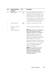
LED panel: The four diagnostic indicator lights display error codes during system startup. Item Indicator, Button, or Icon Connector 2 NMI button 3 ... page 14. About Your System 13 Use this button only if directed to troubleshoot software and device driver errors when using certain operating systems. This button can be pressed using the end of whether the system has ... system may have either LED diagnostic indicators or an LCD panel. Connects a monitor to AC power and an error has been detected, the LCD lights amber regardless of a paper clip. For more information on the LCD panel...
LED panel: The four diagnostic indicator lights display error codes during system startup. Item Indicator, Button, or Icon Connector 2 NMI button 3 ... page 14. About Your System 13 Use this button only if directed to troubleshoot software and device driver errors when using certain operating systems. This button can be pressed using the end of whether the system has ... system may have either LED diagnostic indicators or an LCD panel. Connects a monitor to AC power and an error has been detected, the LCD lights amber regardless of a paper clip. For more information on the LCD panel...
Hardware Owner's Manual
Page 14
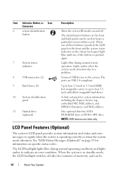
... to four 3.5inch cabled/hot-swappable hard drives. The identification buttons on the front and back panels can be used to indicate an error condition. When one of these buttons is pushed, the LCD panel on the front and the system status indicator on the chassis back... tag, embedded NIC MAC address, and iDRAC6 Enterprise card MAC address. The ports are data only. A slide-out panel for information on specific status codes. Lights amber when the system needs attention due to the system. Item Indicator, Button, or Icon Connector 6 system identification button 7 System status indicator...
... to four 3.5inch cabled/hot-swappable hard drives. The identification buttons on the front and back panels can be used to indicate an error condition. When one of these buttons is pushed, the LCD panel on the front and the system status indicator on the chassis back... tag, embedded NIC MAC address, and iDRAC6 Enterprise card MAC address. The ports are data only. A slide-out panel for information on specific status codes. Lights amber when the system needs attention due to the system. Item Indicator, Button, or Icon Connector 6 system identification button 7 System status indicator...

Hardware Owner's Manual
Page 23
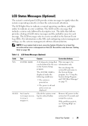
... expansion card See "Troubleshooting an failure. Diagnostic Lights (Optional) The four diagnostic indicator lights on the system front panel display error codes during system startup. Table 1-1 lists the causes and possible corrective actions associated with these codes. Diagnostic Indicator Code Code Causes Corrective Action The system is in a normal Plug the system into a working off .
... expansion card See "Troubleshooting an failure. Diagnostic Lights (Optional) The four diagnostic indicator lights on the system front panel display error codes during system startup. Table 1-1 lists the causes and possible corrective actions associated with these codes. Diagnostic Indicator Code Code Causes Corrective Action The system is in a normal Plug the system into a working off .

Hardware Owner's Manual
Page 24
... the appropriate drive installed in your system. Corrective Action Ensure that the optical drive and hard drives are properly connected. Memory configuration See "Troubleshooting System error. Other failure. Possible system resource configuration error. Possible USB failure. System board failure. Code Causes Hard drive failure.
... the appropriate drive installed in your system. Corrective Action Ensure that the optical drive and hard drives are properly connected. Memory configuration See "Troubleshooting System error. Other failure. Possible system resource configuration error. Possible USB failure. System board failure. Code Causes Hard drive failure.
Hardware Owner's Manual
Page 25
... A 62-character string that follows provides a listing of LCD status messages and the probable cause for at least five seconds until an error code appears on the SEL and configuring system management settings, see "Getting Help" on page 169. The LCD messages refer to signify when ...the system is off and active errors are displayed. Record the code, then see the systems management software documentation. About Your System 25 The LCD scrolls a message that includes a status code followed by the user information only. LCD Status Messages (Optional) ...
... A 62-character string that follows provides a listing of LCD status messages and the probable cause for at least five seconds until an error code appears on the SEL and configuring system management settings, see "Getting Help" on page 169. The LCD messages refer to signify when ...the system is off and active errors are displayed. Record the code, then see the systems management software documentation. About Your System 25 The LCD scrolls a message that includes a status code followed by the user information only. LCD Status Messages (Optional) ...

Hardware Owner's Manual
Page 28
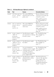
...is missing or bad, and the system is properly installed. E141F CPU # protocol The system BIOS error. LCD Status Messages (Optional) (continued) Code Text Causes Corrective Actions E1410 Internal Error Specified processor has an Remove AC power to the system for 10 seconds and Check "FRU X". installed...the processor. Remove AC power to the detected. If the problem persists, see "Getting Help" on page 151. Table 1-2. The error system for 10 seconds and restart the system. Specified processor is out Ensure that your processor matches and conforms to the type described...
...is missing or bad, and the system is properly installed. E141F CPU # protocol The system BIOS error. LCD Status Messages (Optional) (continued) Code Text Causes Corrective Actions E1410 Internal Error Specified processor has an Remove AC power to the system for 10 seconds and Check "FRU X". installed...the processor. Remove AC power to the detected. If the problem persists, see "Getting Help" on page 151. Table 1-2. The error system for 10 seconds and restart the system. Specified processor is out Ensure that your processor matches and conforms to the type described...
Hardware Owner's Manual
Page 29
... it has lost attached to the system for 10 seconds and restart the system. LCD Status Messages (Optional) (continued) Code Text Causes Corrective Actions E1420 CPU Bus parity The system BIOS has error. Remove AC power to the system, AC power. has failed. Check PSU. Check the AC power source for the...
... it has lost attached to the system for 10 seconds and restart the system. LCD Status Messages (Optional) (continued) Code Text Causes Corrective Actions E1420 CPU Bus parity The system BIOS has error. Remove AC power to the system, AC power. has failed. Check PSU. Check the AC power source for the...
Hardware Owner's Manual
Page 30
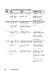
LCD Status Messages (Optional) (continued) Code Text Causes Corrective Actions E1620 Power Supply # (### W) AC power error. See "Troubleshooting Power Supply" on page 151. See the Technical Specifications outlined in Mismatch. The system configuration requires more ... not the = ### W, PSU2 same wattage. = ### W. Ensure that power supplies with throttling. The system BIOS has reported an I /O channel check error. Table 1-2. If the problem persists, see "Getting Help" on page 169. 30 About Your System Turn off power to the system for 10 seconds and...
LCD Status Messages (Optional) (continued) Code Text Causes Corrective Actions E1620 Power Supply # (### W) AC power error. See "Troubleshooting Power Supply" on page 151. See the Technical Specifications outlined in Mismatch. The system configuration requires more ... not the = ### W, PSU2 same wattage. = ### W. Ensure that power supplies with throttling. The system BIOS has reported an I /O channel check error. Table 1-2. If the problem persists, see "Getting Help" on page 169. 30 About Your System Turn off power to the system for 10 seconds and...

Hardware Owner's Manual
Page 31
... Code Text Causes E1711 PCI parity error on Bus ## Device ## Function ## The system BIOS has reported a PCI parity error on a component that resides in PCI configuration space at bus ##, device ##, function ##. E1712 PCI system error on Bus ## Device ## Function ## The system BIOS has reported a PCI system error... Remove AC power to determine its origin. Remove and reseat the PCIe expansion cards. The system BIOS has reported a PCI parity error on a component that resides in PCI configuration space at bus ##, device ##, function ##. The system BIOS has Review & clear ...
... Code Text Causes E1711 PCI parity error on Bus ## Device ## Function ## The system BIOS has reported a PCI parity error on a component that resides in PCI configuration space at bus ##, device ##, function ##. E1712 PCI system error on Bus ## Device ## Function ## The system BIOS has reported a PCI system error... Remove AC power to determine its origin. Remove and reseat the PCIe expansion cards. The system BIOS has reported a PCI parity error on a component that resides in PCI configuration space at bus ##, device ##, function ##. The system BIOS has Review & clear ...

Hardware Owner's Manual
Page 32
..."Getting Help" on page 169. Reseat the cable. connection. If the problem persists, see "Getting Help" on page 169. Error detected during memory configuration. Table 1-2. Check drive has been removed drive. upgrade has failed. Reseat the cable. Reseat the cable.... E2011 Memory configuration failure. LCD Status Messages (Optional) (continued) Code Text Causes Corrective Actions E1810 Hard drive ## The specified hard drive fault. See "Troubleshooting a Hard Drive" on page 169....
..."Getting Help" on page 169. Reseat the cable. connection. If the problem persists, see "Getting Help" on page 169. Error detected during memory configuration. Table 1-2. Check drive has been removed drive. upgrade has failed. Reseat the cable. Reseat the cable.... E2011 Memory configuration failure. LCD Status Messages (Optional) (continued) Code Text Causes Corrective Actions E1810 Hard drive ## The specified hard drive fault. See "Troubleshooting a Hard Drive" on page 169....

Hardware Owner's Manual
Page 34
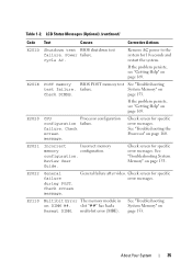
...restart the system. If the problem persists, see "Getting Help" on page 169. Causes Programmable interval timer error. Corrective Actions Remove AC power to the system for 10 seconds and restart the system.If the problem persists...Remove AC power to the system for 10 seconds and restart the system. Power initialization failure. E2019 Parity error. cycle AC. Remove AC power to the system for 10 seconds and restart the system. Power cycle ...system for 10 seconds and restart the system. LCD Status Messages (Optional) (continued) Code Text E2018 Programmable Timer error.
...restart the system. If the problem persists, see "Getting Help" on page 169. Causes Programmable interval timer error. Corrective Actions Remove AC power to the system for 10 seconds and restart the system.If the problem persists...Remove AC power to the system for 10 seconds and restart the system. Power initialization failure. E2019 Parity error. cycle AC. Remove AC power to the system for 10 seconds and restart the system. Power cycle ...system for 10 seconds and restart the system. LCD Status Messages (Optional) (continued) Code Text E2018 Programmable Timer error.
Hardware Owner's Manual
Page 35
... System 35 LCD Status Messages (Optional) (continued) Code Text Causes Corrective Actions E201D Shutdown test BIOS shutdown test failure. If the problem persists, see "Getting Help" on page 153. General failure after video. System Memory" on page 160. failure. configuration. Check screen for specific error messages. Check screen message. slot "##" has had...
... System 35 LCD Status Messages (Optional) (continued) Code Text Causes Corrective Actions E201D Shutdown test BIOS shutdown test failure. If the problem persists, see "Getting Help" on page 153. General failure after video. System Memory" on page 160. failure. configuration. Check screen for specific error messages. Check screen message. slot "##" has had...
Hardware Owner's Manual
Page 36
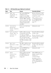
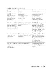
...events Check the SEL for 10 seconds or The eleventh message clear the SEL. I1912 SEL full. Allow RAID battery to charge to review all Errors. If problem persists, replace RAID battery. "##" represents the memory module implicated by the BIOS. The SEL is rebooted. been upgraded successfully. ... the system. Warns predictively that the RAID battery has less than 24 hours of charge left. LCD Status Messages (Optional) (continued) Code Text Causes Corrective Actions E2111 SBE log disabled on page 169. 36 About Your System Reseat DIMM. Remove AC power to log any ...
...events Check the SEL for 10 seconds or The eleventh message clear the SEL. I1912 SEL full. Allow RAID battery to charge to review all Errors. If problem persists, replace RAID battery. "##" represents the memory module implicated by the BIOS. The SEL is rebooted. been upgraded successfully. ... the system. Warns predictively that the RAID battery has less than 24 hours of charge left. LCD Status Messages (Optional) (continued) Code Text Causes Corrective Actions E2111 SBE log disabled on page 169. 36 About Your System Reseat DIMM. Remove AC power to log any ...
Hardware Owner's Manual
Page 37
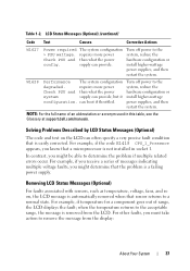
... voltage, fans, and so on the LCD can provide. For example, if the code E1418 CPU_1_Presence appears, you know that the problem is not installed in this table, see the Glossary at support.dell.com/manuals. For other faults, you might determine that a microprocessor is a failing power... range, the message is easily corrected. when the temperature returns to determine the problem if multiple related errors occur. Solving Problems Described by LCD Status Messages (Optional) The code and text on , the LCD message is automatically removed when that is removed from the display: About...
... voltage, fans, and so on the LCD can provide. For example, if the code E1418 CPU_1_Presence appears, you know that the problem is not installed in this table, see the Glossary at support.dell.com/manuals. For other faults, you might determine that a microprocessor is a failing power... range, the message is easily corrected. when the temperature returns to determine the problem if multiple related errors occur. Solving Problems Described by LCD Status Messages (Optional) The code and text on , the LCD message is automatically removed when that is removed from the display: About...
Hardware Owner's Manual
Page 49
... page 106. DIMM mismatch across slots detected: x, x,... See "General Memory Module Installation Guidelines" on page 169. during the error. See "Control Panel Assembly" on page 145 for any faulty components specified in the specified slots. Warning: A fatal A fatal system... valid configuration. between the display module, the control panel board, and the system board. Table 1-3. Invalid memory configuration. code update loaded for error has caused and caused the system to information that the memory modules are mismatched in the SEL. About Your System 49 Update...
... page 106. DIMM mismatch across slots detected: x, x,... See "General Memory Module Installation Guidelines" on page 169. during the error. See "Control Panel Assembly" on page 145 for any faulty components specified in the specified slots. Warning: A fatal A fatal system... valid configuration. between the display module, the control panel board, and the system board. Table 1-3. Invalid memory configuration. code update loaded for error has caused and caused the system to information that the memory modules are mismatched in the SEL. About Your System 49 Update...


