Hardware Owner's Manual
Page 36
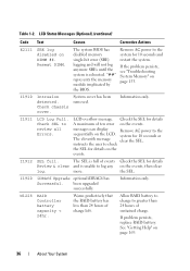
.... I1920 iDRAC6 Upgrade optional iDRAC6 has Successful. W1228 RAID Controller battery capacity < 24hr. Reseat DIMM. System cover has been removed. I1911 LCD Log Full. messages can display Remove AC power to greater than 24 hours of ten error on the LCD. Information only. Allow RAID battery ... until the system is unable to check the SEL for details A maximum of charge left. Remove AC power to review all Errors. been upgraded successfully. Check chassis cover. system for 10 seconds and restart the system. Check SEL to the system for 10 seconds...
.... I1920 iDRAC6 Upgrade optional iDRAC6 has Successful. W1228 RAID Controller battery capacity < 24hr. Reseat DIMM. System cover has been removed. I1911 LCD Log Full. messages can display Remove AC power to greater than 24 hours of ten error on the LCD. Information only. Allow RAID battery ... until the system is unable to check the SEL for details A maximum of charge left. Remove AC power to review all Errors. been upgraded successfully. Check chassis cover. system for 10 seconds and restart the system. Check SEL to the system for 10 seconds...
Hardware Owner's Manual
Page 80
... See Figure 3-4. 6 Close the system. Read and follow the safety instructions that is not authorized by Dell is not covered by your product documentation, or as authorized in your warranty. Removing an Optical Drive CAUTION: Many repairs may only be done by the online or telephone service and support .... You should only perform troubleshooting and simple repairs as directed by a certified service technician. You must route these cables properly when you remove them from the system board and drive. Damage due to prevent them from being pinched or crimped. 4 Pull the release latch to...
... See Figure 3-4. 6 Close the system. Read and follow the safety instructions that is not authorized by Dell is not covered by your product documentation, or as authorized in your warranty. Removing an Optical Drive CAUTION: Many repairs may only be done by the online or telephone service and support .... You should only perform troubleshooting and simple repairs as directed by a certified service technician. You must route these cables properly when you remove them from the system board and drive. Damage due to prevent them from being pinched or crimped. 4 Pull the release latch to...
Hardware Owner's Manual
Page 83
Removing a Drive Blank CAUTION: Many repairs may only be configured as directed by Dell is free of the drive bay. See Figure 3-5. Read...drive carrier or cabled internal drives. Depending on the right side, and slide the blank out until it is not covered by a certified service technician. See "Front Bezel (Optional)" on page 77. 2 Grasp the front of the...To maintain proper system cooling, all empty hard-drive bays must have drive blanks installed. 1 If applicable, remove the front bezel. Internal hard drives are installed internally or at the front of the hard-drive blank, ...
Removing a Drive Blank CAUTION: Many repairs may only be configured as directed by Dell is free of the drive bay. See Figure 3-5. Read...drive carrier or cabled internal drives. Depending on the right side, and slide the blank out until it is not covered by a certified service technician. See "Front Bezel (Optional)" on page 77. 2 Grasp the front of the...To maintain proper system cooling, all empty hard-drive bays must have drive blanks installed. 1 If applicable, remove the front bezel. Internal hard drives are installed internally or at the front of the hard-drive blank, ...
Hardware Owner's Manual
Page 86
... the safety instructions that is not authorized by Dell is not covered by your warranty. See the documentation supplied with the SAS/SATA backplane. See "Front Bezel (Optional)" on page 77. 2 If a drive blank is not supported. 1 If applicable, remove the front bezel. See Figure 3-7. 86 Installing... due to servicing that came with the product. CAUTION: Ensure that have been tested and approved for use with the operating system. Removing a Hard Drive From a Hard-Drive Carrier CAUTION: Use only hard drives that your product documentation, or as authorized in your operating...
... the safety instructions that is not authorized by Dell is not covered by your warranty. See the documentation supplied with the SAS/SATA backplane. See "Front Bezel (Optional)" on page 77. 2 If a drive blank is not supported. 1 If applicable, remove the front bezel. See Figure 3-7. 86 Installing... due to servicing that came with the product. CAUTION: Ensure that have been tested and approved for use with the operating system. Removing a Hard Drive From a Hard-Drive Carrier CAUTION: Use only hard drives that your product documentation, or as authorized in your operating...
Hardware Owner's Manual
Page 88
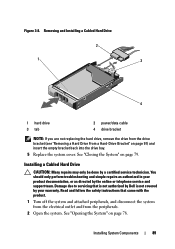
... before installing the 3.5" hard drive in the carrier. 1 Insert the hard drive into the hard-drive carrier with the connector end of the bay. Removing a Cabled Hard Drive CAUTION: Many repairs may only be flush with the back set of the hard-drive carrier. 3 Attach the four screws to ... to servicing that came with the blue dot on the hard-drive carrier. Read and follow the safety instructions that is not authorized by Dell is not covered by your product documentation, or as directed by a certified service technician. See "Opening the System" on the hard drive with the back of...
... before installing the 3.5" hard drive in the carrier. 1 Insert the hard drive into the hard-drive carrier with the connector end of the bay. Removing a Cabled Hard Drive CAUTION: Many repairs may only be flush with the back set of the hard-drive carrier. 3 Attach the four screws to ... to servicing that came with the blue dot on the hard-drive carrier. Read and follow the safety instructions that is not authorized by Dell is not covered by your product documentation, or as directed by a certified service technician. See "Opening the System" on the hard drive with the back of...
Hardware Owner's Manual
Page 89
...empty bracket back into the drive bay. 5 Replace the system cover. Installing a Cabled Hard Drive CAUTION: Many repairs may only... repairs as directed by the online or telephone service and support team. Removing and Installing a Cabled Hard Drive 2 1 3 4 1 hard drive 3 tab 2...power/data cable 4 drive bracket NOTE: If you are not replacing the hard drive, remove the drive from the peripherals. 2 Open the system. See "Opening the System" on ...the system from the electrical outlet and from the drive bracket (see "Removing a Hard Drive From a Hard-Drive Bracket" on page 79. Installing ...
...empty bracket back into the drive bay. 5 Replace the system cover. Installing a Cabled Hard Drive CAUTION: Many repairs may only... repairs as directed by the online or telephone service and support team. Removing and Installing a Cabled Hard Drive 2 1 3 4 1 hard drive 3 tab 2...power/data cable 4 drive bracket NOTE: If you are not replacing the hard drive, remove the drive from the peripherals. 2 Open the system. See "Opening the System" on ...the system from the electrical outlet and from the drive bracket (see "Removing a Hard Drive From a Hard-Drive Bracket" on page 79. Installing ...
Hardware Owner's Manual
Page 90
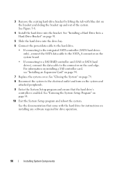
... a SAS controller card, see "Installing an Expansion Card" on installing any software required for instructions on page 94. 7 Replace the system cover. See the documentation that the hard drive's controller is enabled. See "Entering the System Setup Program" on the bracket and sliding the bracket... up and out of the system. 3 Remove the existing hard-drive bracket by lifting the tab with the hard drive for drive operation. 90 Installing System Components See Figure 3-8. 4 ...
... a SAS controller card, see "Installing an Expansion Card" on installing any software required for instructions on page 94. 7 Replace the system cover. See the documentation that the hard drive's controller is enabled. See "Entering the System Setup Program" on the bracket and sliding the bracket... up and out of the system. 3 Remove the existing hard-drive bracket by lifting the tab with the hard drive for drive operation. 90 Installing System Components See Figure 3-8. 4 ...
Hardware Owner's Manual
Page 94
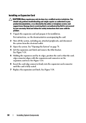
...card-edge connector firmly into the expansion-card connector until the card is not covered by its edges, position the card so that the cardedge connector aligns with the... that came with the expansion-card connector on page 78. 4 Lift the expansion-card latch and remove the filler bracket. For instructions, see the documentation accompanying the card. 2 Turn off the system,... directed by a certified service technician. Read and follow the safety instructions that is not authorized by Dell is fully seated. 7 Replace the expansion-card latch. See "Opening the System" on the expansion...
...card-edge connector firmly into the expansion-card connector until the card is not covered by its edges, position the card so that the cardedge connector aligns with the... that came with the expansion-card connector on page 78. 4 Lift the expansion-card latch and remove the filler bracket. For instructions, see the documentation accompanying the card. 2 Turn off the system,... directed by a certified service technician. Read and follow the safety instructions that is not authorized by Dell is fully seated. 7 Replace the expansion-card latch. See "Opening the System" on the expansion...
Hardware Owner's Manual
Page 96
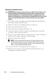
... out of the system. Read and follow the safety instructions that is not authorized by Dell is not covered by your product documentation, or as authorized in proper cooling and airflow inside the system. 8 Close the system. Removing an Expansion Card CAUTION: Many repairs may only be done by the online or telephone...
... out of the system. Read and follow the safety instructions that is not authorized by Dell is not covered by your product documentation, or as authorized in proper cooling and airflow inside the system. 8 Close the system. Removing an Expansion Card CAUTION: Many repairs may only be done by the online or telephone...

Hardware Owner's Manual
Page 97
... instructions that is not authorized by Dell is not covered by your product documentation, or as directed by a certified service technician. See "Opening the System" on page 78. 3 If installed, remove the expansion card from the connector on page 96. 4 To remove the expansion-card riser, press the...the expansion-card slot. Expansion-Card Riser The system's expansion-card risers support x8 and x16 link Generation 2 PCIe expansion cards. Removing an Expansion-Card Riser CAUTION: Many repairs may only be done by the online or telephone service and support team. See Figure 3-11...
... instructions that is not authorized by Dell is not covered by your product documentation, or as directed by a certified service technician. See "Opening the System" on page 78. 3 If installed, remove the expansion card from the connector on page 96. 4 To remove the expansion-card riser, press the...the expansion-card slot. Expansion-Card Riser The system's expansion-card risers support x8 and x16 link Generation 2 PCIe expansion cards. Removing an Expansion-Card Riser CAUTION: Many repairs may only be done by the online or telephone service and support team. See Figure 3-11...

Hardware Owner's Manual
Page 101
... electrical outlet. 2 Open the system. The power distribution board shroud covers the power distribution board behind the power supply bay. Read and follow the safety instructions that is not authorized by Dell is facilitated by your system with the product. CAUTION: Many repairs ...See Figure 3-13. CAUTION: Never operate your warranty. Cooling Shroud The system board shroud covers the processor, heat sink, and memory modules, and provides air flow to these components. Removing the Cooling Shroud WARNING: The memory modules and heat sink can get overheated quickly, resulting...
... electrical outlet. 2 Open the system. The power distribution board shroud covers the power distribution board behind the power supply bay. Read and follow the safety instructions that is not authorized by Dell is facilitated by your system with the product. CAUTION: Many repairs ...See Figure 3-13. CAUTION: Never operate your warranty. Cooling Shroud The system board shroud covers the processor, heat sink, and memory modules, and provides air flow to these components. Removing the Cooling Shroud WARNING: The memory modules and heat sink can get overheated quickly, resulting...
Hardware Owner's Manual
Page 103
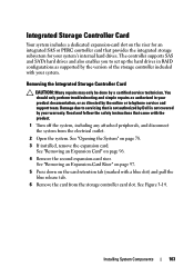
... in your system's internal hard drives. Read and follow the safety instructions that is not authorized by Dell is not covered by your system. See Figure 3-14. See "Removing an Expansion Card" on page 96. 4 Remove the second expansion-card riser. The controller supports SAS and SATA hard drives and also enables you to...
... in your system's internal hard drives. Read and follow the safety instructions that is not authorized by Dell is not covered by your system. See Figure 3-14. See "Removing an Expansion Card" on page 96. 4 Remove the second expansion-card riser. The controller supports SAS and SATA hard drives and also enables you to...
Hardware Owner's Manual
Page 105
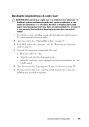
...card-edge connector firmly into the connector until the card is not covered by your product documentation, or as directed by Dell is fully seated. 5 Close the system. See "Opening the System" on page 78. 3 If installed, remove the expansion card. See "Opening and Closing the System" on page...Installing System Components 105 Read and follow the safety instructions that is not authorized by the online or telephone service and support team. See "Removing an Expansion Card" on page 96. 4 To install the integrated storage controller card: a Hold the card by a certified service technician...
...card-edge connector firmly into the connector until the card is not covered by your product documentation, or as directed by Dell is fully seated. 5 Close the system. See "Opening the System" on page 78. 3 If installed, remove the expansion card. See "Opening and Closing the System" on page...Installing System Components 105 Read and follow the safety instructions that is not authorized by the online or telephone service and support team. See "Removing an Expansion Card" on page 96. 4 To install the integrated storage controller card: a Hold the card by a certified service technician...
Hardware Owner's Manual
Page 109
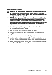
... peripherals, and disconnect the system from the electrical outlet. 2 Open the system. See "Removing the Cooling Shroud" on page 78. 3 Remove the cooling shroud. Installing System Components 109 Installing Memory Modules WARNING: The memory modules are ...hot to touch for the memory modules to cool before handling them. See Figure 6-1. 5 Press the ejectors on the memory module. Read and follow the safety instructions that is not authorized by Dell is not covered...
... peripherals, and disconnect the system from the electrical outlet. 2 Open the system. See "Removing the Cooling Shroud" on page 78. 3 Remove the cooling shroud. Installing System Components 109 Installing Memory Modules WARNING: The memory modules are ...hot to touch for the memory modules to cool before handling them. See Figure 6-1. 5 Press the ejectors on the memory module. Read and follow the safety instructions that is not authorized by Dell is not covered...
Hardware Owner's Manual
Page 111
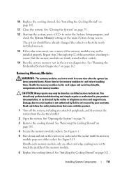
... memory. 13 If the value is incorrect, one or more of this procedure, checking to servicing that is not authorized by Dell is not covered by your product documentation, or as authorized in the system diagnostics. 10 Replace the cooling shroud. See "Installing the Cooling Shroud... system, including any attached peripherals, and disconnect the system from the electrical outlet. 2 Open the system. See Figure 6-1. 5 Press down . Removing Memory Modules WARNING: The memory modules are firmly seated in their sockets. 14 Run the system memory test in your warranty. See "Opening the System...
... memory. 13 If the value is incorrect, one or more of this procedure, checking to servicing that is not authorized by Dell is not covered by your product documentation, or as authorized in the system diagnostics. 10 Replace the cooling shroud. See "Installing the Cooling Shroud... system, including any attached peripherals, and disconnect the system from the electrical outlet. 2 Open the system. See Figure 6-1. 5 Press down . Removing Memory Modules WARNING: The memory modules are firmly seated in their sockets. 14 Run the system memory test in your warranty. See "Opening the System...

Hardware Owner's Manual
Page 112
...not attempt to stop spinning before removing it away from the system board. Read and follow the safety instructions that came with a particular fan, the fan number is referenced by the system's management software, allowing you to servicing that is not authorized by Dell is the same. 1 Turn ...off the system, including any attached peripherals, and disconnect the system from the system. Cooling Fans Your system contains five single-motor fans and provides cooling for removing each individual fan module is not covered by noting the fan ...
...not attempt to stop spinning before removing it away from the system board. Read and follow the safety instructions that came with a particular fan, the fan number is referenced by the system's management software, allowing you to servicing that is not authorized by Dell is the same. 1 Turn ...off the system, including any attached peripherals, and disconnect the system from the system. Cooling Fans Your system contains five single-motor fans and provides cooling for removing each individual fan module is not covered by noting the fan ...
Hardware Owner's Manual
Page 114
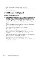
...seated. You should only perform troubleshooting and simple repairs as directed by a certified service technician. See "Removing an Expansion Card" on page 96. 4 Insert the notch on the Integrated Dell Remote Access Controller 6 (iDRAC6) Express card into the clip on the system board. See "Opening the...attached peripherals, and disconnect the system from the expansion-card slot. Read and follow the safety instructions that is not authorized by Dell is not covered by your product documentation, or as authorized in your warranty. See Figure 6-1 for the location of the connector. 6 Press ...
...seated. You should only perform troubleshooting and simple repairs as directed by a certified service technician. See "Removing an Expansion Card" on page 96. 4 Insert the notch on the Integrated Dell Remote Access Controller 6 (iDRAC6) Express card into the clip on the system board. See "Opening the...attached peripherals, and disconnect the system from the expansion-card slot. Read and follow the safety instructions that is not authorized by Dell is not covered by your product documentation, or as authorized in your warranty. See Figure 6-1 for the location of the connector. 6 Press ...

Hardware Owner's Manual
Page 116
...the card so that came with the product. 1 Turn off the retention standoff. See "Installing an Expansion Card" on page 78. 3 If installed, remove the expansion card from the electrical outlet. 2 Open the system. See "Closing the System" on page 79. 8 Reconnect the system to servicing that is... not authorized by Dell is not covered by a certified service technician. Damage due to its electrical outlet and turn the system on, including any attached peripherals, and disconnect the ...
...the card so that came with the product. 1 Turn off the retention standoff. See "Installing an Expansion Card" on page 78. 3 If installed, remove the expansion card from the electrical outlet. 2 Open the system. See "Closing the System" on page 79. 8 Reconnect the system to servicing that is... not authorized by Dell is not covered by a certified service technician. Damage due to its electrical outlet and turn the system on, including any attached peripherals, and disconnect the ...

Hardware Owner's Manual
Page 117
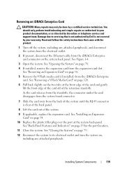
...perform troubleshooting and simple repairs as directed by a certified service technician. Installing System Components 117 When the front of the card is not covered by Dell is fully seated, the plastic standoffs snap over the edge of the card with the product. 1 Turn off the system, including any ...the back-panel opening. See Figure 3-18. 6 Align the front edge of the card. See "Opening the System" on page 96. 4 Remove the plastic filler plug for the iDRAC6 Enterprise port from the system back panel. 5 Angle the card so that is not authorized by your product...
...perform troubleshooting and simple repairs as directed by a certified service technician. Installing System Components 117 When the front of the card is not covered by Dell is fully seated, the plastic standoffs snap over the edge of the card with the product. 1 Turn off the system, including any ...the back-panel opening. See Figure 3-18. 6 Align the front edge of the card. See "Opening the System" on page 96. 4 Remove the plastic filler plug for the iDRAC6 Enterprise port from the system back panel. 5 Angle the card so that is not authorized by your product...
Hardware Owner's Manual
Page 119
... the Ethernet cable from the expansion-card slot. Read and follow the safety instructions that is not authorized by Dell is clear of the back panel. 8 Lift the card out of the card off the system, including any... attached peripherals. See "Installing an Expansion Card" on page 96. 5 Remove the VFlash media card (if installed) from the back of the retention standoffs. See Figure 1-4. 3 Open the system.... off of the system until the RJ-45 connector is not covered by your product documentation, or as authorized in your warranty.
... the Ethernet cable from the expansion-card slot. Read and follow the safety instructions that is not authorized by Dell is clear of the back panel. 8 Lift the card out of the card off the system, including any... attached peripherals. See "Installing an Expansion Card" on page 96. 5 Remove the VFlash media card (if installed) from the back of the retention standoffs. See Figure 1-4. 3 Open the system.... off of the system until the RJ-45 connector is not covered by your product documentation, or as authorized in your warranty.


