Hardware Owner's Manual (PDF)
Page 5
... 58 Optical Drive 60 Removing the Optical Drive 60 Installing the Optical Drive 61 Configuring the Boot Drive 62 Hard Drives 62 Removing a Hard Drive 63 Installing a Hard Drive 67 Installing a SAS Controller Card 68 Fan Assembly 68 Removing the Fan Assembly 69 Installing the Fan Assembly 70 Optional PCI Fan Assembly 71 Removing the PCI Fan Assembly 71 Installing the PCI Fan Assembly 72 Power...
... 58 Optical Drive 60 Removing the Optical Drive 60 Installing the Optical Drive 61 Configuring the Boot Drive 62 Hard Drives 62 Removing a Hard Drive 63 Installing a Hard Drive 67 Installing a SAS Controller Card 68 Fan Assembly 68 Removing the Fan Assembly 69 Installing the Fan Assembly 70 Optional PCI Fan Assembly 71 Removing the PCI Fan Assembly 71 Installing the PCI Fan Assembly 72 Power...

Hardware Owner's Manual (PDF)
Page 51
Installing System Components This section describes how to install the following system components: • Cooling shroud • System battery • Optical drive • Hard drives • Fan assembly • Optional PCI fan • Power supply • Expansion cards • Riser card • System memory • Processor • Control panel • System board Recommended ...
Installing System Components This section describes how to install the following system components: • Cooling shroud • System battery • Optical drive • Hard drives • Fan assembly • Optional PCI fan • Power supply • Expansion cards • Riser card • System memory • Processor • Control panel • System board Recommended ...
Hardware Owner's Manual (PDF)
Page 68
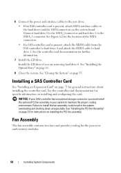
... two fans and provides cooling for further information. 7 Install the CD drive. Install the CD drive if you must install the optional PCI fan assembly in your SAS controller has an external storage connector, you are removing hard drive 0. See "Closing the System" on the system board. Failure to maintain the proper cooling environment. 6 Connect...
... two fans and provides cooling for further information. 7 Install the CD drive. Install the CD drive if you must install the optional PCI fan assembly in your SAS controller has an external storage connector, you are removing hard drive 0. See "Closing the System" on the system board. Failure to maintain the proper cooling environment. 6 Connect...

Hardware Owner's Manual (PDF)
Page 69
... out of the chassis. Installing System Components 69 Before performing any of the fan assembly's cable tray. See "Removing the Cooling Shroud" on page 56. 3 Disconnect the fan assembly's power cable from hard drive 1 if installed. See Figure 3-11. 4 Remove the data cable from the system... board. Removing the Fan Assembly CAUTION: Only trained service technicians are authorized to remove the system cover and...
... out of the chassis. Installing System Components 69 Before performing any of the fan assembly's cable tray. See "Removing the Cooling Shroud" on page 56. 3 Disconnect the fan assembly's power cable from hard drive 1 if installed. See Figure 3-11. 4 Remove the data cable from the system... board. Removing the Fan Assembly CAUTION: Only trained service technicians are authorized to remove the system cover and...

Hardware Owner's Manual (PDF)
Page 70
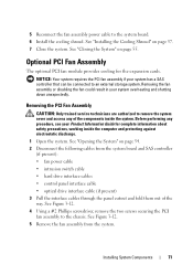
Figure 3-11. See Figure 3-11. 4 Reconnect the hard drive 1 data cable to the hard drive. See Figure 3-11. 2 Lower the fan assembly until the release levers snap onto the securing posts. 3 Route the cables in the fan assembly with the two fan assembly securing posts. See Figure 3-11. 70 Installing System Components Installing and Removing the Fan Assembly 1 2 5 3 4 1 release levers (2) 2 4 hard drive 1 data cable 5 power cable cable tray 3 securing posts (2) Installing the Fan Assembly 1 Align the holes in the fan assembly cable tray.
Figure 3-11. See Figure 3-11. 4 Reconnect the hard drive 1 data cable to the hard drive. See Figure 3-11. 2 Lower the fan assembly until the release levers snap onto the securing posts. 3 Route the cables in the fan assembly with the two fan assembly securing posts. See Figure 3-11. 70 Installing System Components Installing and Removing the Fan Assembly 1 2 5 3 4 1 release levers (2) 2 4 hard drive 1 data cable 5 power cable cable tray 3 securing posts (2) Installing the Fan Assembly 1 Align the holes in the fan assembly cable tray.
Hardware Owner's Manual (PDF)
Page 71
... board. 6 Install the cooling shroud. See Figure 3-12. 5 Remove the fan assembly from the system board and SAS controller (if present): • fan power cable • intrusion switch cable • hard drive interface cables • control panel interface cable • optical drive interface cable (if present) 3 Pull the interface cables through the panel cutout...
... board. 6 Install the cooling shroud. See Figure 3-12. 5 Remove the fan assembly from the system board and SAS controller (if present): • fan power cable • intrusion switch cable • hard drive interface cables • control panel interface cable • optical drive interface cable (if present) 3 Pull the interface cables through the panel cutout...

Hardware Owner's Manual (PDF)
Page 91
.... See Figure 6-2. 7 Disconnect the hard-drive interface cables: a If a SAS controller is installed, disconnect the interface cable from the FP_CONN1 connector on the board. See Figure 3-20. 4 Close the system. Removing the System Board Assembly CAUTION: Only trained service technicians are connected... to ensure proper installation. 5 If applicable, disconnect the optical drive interface cable from the SATA_0 and SATA_1 connectors on the system board....
.... See Figure 6-2. 7 Disconnect the hard-drive interface cables: a If a SAS controller is installed, disconnect the interface cable from the FP_CONN1 connector on the board. See Figure 3-20. 4 Close the system. Removing the System Board Assembly CAUTION: Only trained service technicians are connected... to ensure proper installation. 5 If applicable, disconnect the optical drive interface cable from the SATA_0 and SATA_1 connectors on the system board....
Hardware Owner's Manual (PDF)
Page 94
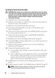
... the processor and heat sink. Before performing any procedure, see your configuration uses the integrated controller, reconnect the hard drive 0 interface cable to the SATA_0 connector and the hard drive 1 interface cable to the SATA_1 connector on page 82. b If your Product Information Guide for the location .... See "Installing the Riser Card" on the plunger that secures the system board tray to the chassis. Installing the System Board Assembly CAUTION: Only trained service technicians are authorized to remove the system cover and access any PCI expansion cards that you installed a SAS...
... the processor and heat sink. Before performing any procedure, see your configuration uses the integrated controller, reconnect the hard drive 0 interface cable to the SATA_0 connector and the hard drive 1 interface cable to the SATA_1 connector on page 82. b If your Product Information Guide for the location .... See "Installing the Riser Card" on the plunger that secures the system board tray to the chassis. Installing the System Board Assembly CAUTION: Only trained service technicians are authorized to remove the system cover and access any PCI expansion cards that you installed a SAS...
Hardware Owner's Manual (PDF)
Page 178
...Dell PowerEdge Diagnostics, 117 when to use, 118 diagnostics indicator codes, 29 drives CD, 60 optical, 60 features back-panel, 17 front-panel, 13 H hard drives configuring the boot drive, 62 installing, 67 removing, 63 troubleshooting, 111 E error messages, 35 expansion cards installing, 75 removing, 78 troubleshooting, 113 external devices connecting, 18 F fan assembly... installing bezel, 54 CD drive, 61 control panel, 90 cooling shroud, 57 expansion cards, 75 hard drives, 67 memory modules, 82 optical drive, 61 PCI fan assembly, 72 power supply, 75 processor fan assembly, 70 riser card, 80...
...Dell PowerEdge Diagnostics, 117 when to use, 118 diagnostics indicator codes, 29 drives CD, 60 optical, 60 features back-panel, 17 front-panel, 13 H hard drives configuring the boot drive, 62 installing, 67 removing, 63 troubleshooting, 111 E error messages, 35 expansion cards installing, 75 removing, 78 troubleshooting, 113 external devices connecting, 18 F fan assembly... installing bezel, 54 CD drive, 61 control panel, 90 cooling shroud, 57 expansion cards, 75 hard drives, 67 memory modules, 82 optical drive, 61 PCI fan assembly, 72 power supply, 75 processor fan assembly, 70 riser card, 80...
Hardware Owner's Manual (PDF)
Page 180
...Dell, 133 system battery replacing, 58 troubleshooting, 106 system board connectors, 122 installing, 94 jumpers, 121 removing, 91 system cooling troubleshooting, 107 system features accessing, 12 recommended tools, 51 removing bezel, 53 CD drive, 60 control panel, 89 cooling shroud, 56 expansion cards, 78 hard drives, 63 memory modules, 84 optical drive, 60 PCI fan assembly..., 71 power supply, 73 processor fan assembly, 69 riser card, 79...
...Dell, 133 system battery replacing, 58 troubleshooting, 106 system board connectors, 122 installing, 94 jumpers, 121 removing, 91 system cooling troubleshooting, 107 system features accessing, 12 recommended tools, 51 removing bezel, 53 CD drive, 60 control panel, 89 cooling shroud, 56 expansion cards, 78 hard drives, 63 memory modules, 84 optical drive, 60 PCI fan assembly..., 71 power supply, 73 processor fan assembly, 69 riser card, 79...


