Information Update
Page 2
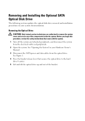
... and Installing the Optional SATA Optical Disk Drive The following section updates the optical disk drive removal and installation procedures in your system documentation. Removing the Optical Drive CAUTION: Only trained service technicians are authorized to the hard drive 0 carrier. 5 Lift and tilt the optical drive up and out of the components inside the system. See...
... and Installing the Optional SATA Optical Disk Drive The following section updates the optical disk drive removal and installation procedures in your system documentation. Removing the Optical Drive CAUTION: Only trained service technicians are authorized to the hard drive 0 carrier. 5 Lift and tilt the optical drive up and out of the components inside the system. See...
Information Update
Page 3
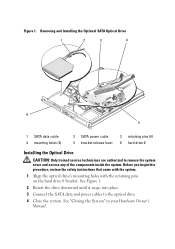
... instructions that came with the system. 1 Align the optical drive's mounting holes with the retaining pins on the hard drive 0 bracket. Removing and Installing the Optional SATA Optical Drive 1 2 3 4 6 5 1 SATA data cable 4 mounting holes (4) 2 SATA power cable 5 bracket release lever 3 retaining pins (4) 6 hard drive 0 Installing the Optical Drive CAUTION: Only trained service technicians are authorized to the...
... instructions that came with the system. 1 Align the optical drive's mounting holes with the retaining pins on the hard drive 0 bracket. Removing and Installing the Optional SATA Optical Drive 1 2 3 4 6 5 1 SATA data cable 4 mounting holes (4) 2 SATA power cable 5 bracket release lever 3 retaining pins (4) 6 hard drive 0 Installing the Optical Drive CAUTION: Only trained service technicians are authorized to the...

Getting Started Guide
Page 5
...Series. • A minimum of 512 MB of 667-MHz or 800-MHz DDR2 SDRAM memory, upgradable to two internal, 1-inch high, SATA hard drives with an optional SAS controller card. • Optional remote access controller for static rails and sliding rails. Up to a maximum of 8 GB...512-MB, 1-GB, or 2-GB unbuffered ECC memory modules in four memory module sockets on the system board. • One of the following internal hard-drive configurations: - Getting Started Guide 3 Intel® Celeron® - Dual-Core Intel Xeon® Processor 3000 Series - Up to view processor information...
...Series. • A minimum of 512 MB of 667-MHz or 800-MHz DDR2 SDRAM memory, upgradable to two internal, 1-inch high, SATA hard drives with an optional SAS controller card. • Optional remote access controller for static rails and sliding rails. Up to a maximum of 8 GB...512-MB, 1-GB, or 2-GB unbuffered ECC memory modules in four memory module sockets on the system board. • One of the following internal hard-drive configurations: - Getting Started Guide 3 Intel® Celeron® - Dual-Core Intel Xeon® Processor 3000 Series - Up to view processor information...
Getting Started Guide
Page 14
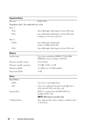
One optional drive that emulates a diskette drive or hard drive 12 Getting Started Guide Two optional riser cards Riser 1 PCIe One full-height, half-length, x8 lane PCIe slot PCIe One full-height, half-length, ... SDRAM memory modules with ECC Four 240-pin 512 MB, 1 GB, or 2 GB 512 MB (one 512-MB module) 8 GB Drives Hard Drives SATA SAS Optical drive USB flash drive Up to two 1-inch high drives Up to two optional internal 1-inch high drives with optional SAS controller card DVD, or combination CD-RW/DVD in a peripheral...
One optional drive that emulates a diskette drive or hard drive 12 Getting Started Guide Two optional riser cards Riser 1 PCIe One full-height, half-length, x8 lane PCIe slot PCIe One full-height, half-length, ... SDRAM memory modules with ECC Four 240-pin 512 MB, 1 GB, or 2 GB 512 MB (one 512-MB module) 8 GB Drives Hard Drives SATA SAS Optical drive USB flash drive Up to two 1-inch high drives Up to two optional internal 1-inch high drives with optional SAS controller card DVD, or combination CD-RW/DVD in a peripheral...
Hardware Owner's Manual (PDF)
Page 5
... Cooling Shroud 56 Installing the Cooling Shroud 57 System Battery 58 Replacing the System Battery 58 Optical Drive 60 Removing the Optical Drive 60 Installing the Optical Drive 61 Configuring the Boot Drive 62 Hard Drives 62 Removing a Hard Drive 63 Installing a Hard Drive 67 Installing a SAS Controller Card 68 Fan Assembly 68 Removing the Fan Assembly 69 Installing the...
... Cooling Shroud 56 Installing the Cooling Shroud 57 System Battery 58 Replacing the System Battery 58 Optical Drive 60 Removing the Optical Drive 60 Installing the Optical Drive 61 Configuring the Boot Drive 62 Hard Drives 62 Removing a Hard Drive 63 Installing a Hard Drive 67 Installing a SAS Controller Card 68 Fan Assembly 68 Removing the Fan Assembly 69 Installing the...
Hardware Owner's Manual (PDF)
Page 7
... 106 Troubleshooting System Cooling Problems 107 Troubleshooting a Fan 108 Troubleshooting System Memory 108 Troubleshooting an Optical Drive 110 Troubleshooting a Hard Drive 111 Troubleshooting Expansion Cards 113 Troubleshooting the Microprocessor 114 5 Running the System Diagnostics . . . . . 117 Using Dell PowerEdge Diagnostics 117 System Diagnostics Features 117 When to Use the System Diagnostics 118 Running the System Diagnostics...
... 106 Troubleshooting System Cooling Problems 107 Troubleshooting a Fan 108 Troubleshooting System Memory 108 Troubleshooting an Optical Drive 110 Troubleshooting a Hard Drive 111 Troubleshooting Expansion Cards 113 Troubleshooting the Microprocessor 114 5 Running the System Diagnostics . . . . . 117 Using Dell PowerEdge Diagnostics 117 System Diagnostics Features 117 When to Use the System Diagnostics 118 Running the System Diagnostics...
Hardware Owner's Manual (PDF)
Page 16
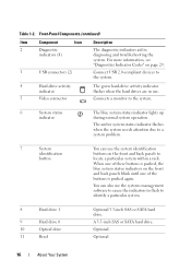
...the system identification buttons on the front and back panels to identify a particular system. 8 Hard drive 1 9 Hard drive 0 10 Optical drive 11 Bezel Optional 3.5-inch SAS or SATA hard drive. The amber system status indicator flashes when the system needs attention due to a system ... locate a particular system within a rack. Connects a monitor to the system. 4 Hard-drive activity indicator 5 Video connector The green hard-drive activity indicator flashes when the hard drives are in diagnosing and troubleshooting the system. Optional 16 About Your System Table 1-2.
...the system identification buttons on the front and back panels to identify a particular system. 8 Hard drive 1 9 Hard drive 0 10 Optical drive 11 Bezel Optional 3.5-inch SAS or SATA hard drive. The amber system status indicator flashes when the system needs attention due to a system ... locate a particular system within a rack. Connects a monitor to the system. 4 Hard-drive activity indicator 5 Video connector The green hard-drive activity indicator flashes when the hard drives are in diagnosing and troubleshooting the system. Optional 16 About Your System Table 1-2.
Hardware Owner's Manual (PDF)
Page 20
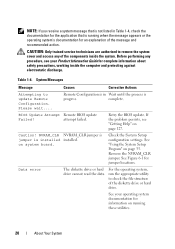
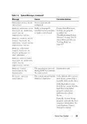
... recommended action. System Messages Message Causes Corrective Actions Attempting to check the file structure of the diskette drive or hard drive. BIOS Update Attempt Remote BIOS update Failed! Retry the BIOS update. Data error The diskette drive or hard drive cannot read the data. Before performing any of the components inside the computer and protecting against...
... recommended action. System Messages Message Causes Corrective Actions Attempting to check the file structure of the diskette drive or hard drive. BIOS Update Attempt Remote BIOS update Failed! Retry the BIOS update. Data error The diskette drive or hard drive cannot read the data. Before performing any of the components inside the computer and protecting against...
Hardware Owner's Manual (PDF)
Page 23
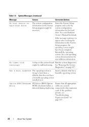
If the hard drive is your boot device, ensure that a bootable disk is installed, properly seated, and partitioned as a boot device. Enter the System Setup program and verify the ... write/read value or faulty system board. installed. boot device, ensure that the hard drive is in the drive. Table 1-4. No boot device available The system cannot find the If the diskette drive is incorrectly detected configured. See your diskette or hard drive. Memory address line Faulty or improperly Ensure that all memory failure at address...
If the hard drive is your boot device, ensure that a bootable disk is installed, properly seated, and partitioned as a boot device. Enter the System Setup program and verify the ... write/read value or faulty system board. installed. boot device, ensure that the hard drive is in the drive. Table 1-4. No boot device available The system cannot find the If the diskette drive is incorrectly detected configured. See your diskette or hard drive. Memory address line Faulty or improperly Ensure that all memory failure at address...
Hardware Owner's Manual (PDF)
Page 24
..., see "Troubleshooting Expansion Cards" on it. See your operating system documentation for reinstallation information. See your Hardware Owner's Manual for the hard drive. No timer tick interrupt A chip on hard-disk drive The system configuration information in the System Setup program, the operating system might be incorrect. Not a boot diskette The operating system is...
..., see "Troubleshooting Expansion Cards" on it. See your operating system documentation for reinstallation information. See your Hardware Owner's Manual for the hard drive. No timer tick interrupt A chip on hard-disk drive The system configuration information in the System Setup program, the operating system might be incorrect. Not a boot diskette The operating system is...
Hardware Owner's Manual (PDF)
Page 26
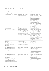
.... See "Troubleshooting a Hard Drive" on page 102 or is defective. Parameters hard disk drive failure. Ensure that the hard drive cables are properly connected. SATA port 0/1/2 hard disk drive failure SATA port 0/1/2 hard disk drive auto-sensing error Faulty drive. INT13 call failure from the Ensure that the diskette diskette or hard drive, the and hard-drive cables are properly connected. See "Troubleshooting a Hard Drive" on page...
.... See "Troubleshooting a Hard Drive" on page 102 or is defective. Parameters hard disk drive failure. Ensure that the hard drive cables are properly connected. SATA port 0/1/2 hard disk drive failure SATA port 0/1/2 hard disk drive auto-sensing error Faulty drive. INT13 call failure from the Ensure that the diskette diskette or hard drive, the and hard-drive cables are properly connected. See "Troubleshooting a Hard Drive" on page...
Hardware Owner's Manual (PDF)
Page 27
.... Table 1-4. System Messages (continued) Message Causes Corrective Actions SATA Port 0/1/2 SATA Port 0/1/2 set as Auto, Run the System Setup hard disk not found Seek error Seek operation failed Faulty diskette or hard drive. The amount of -day clock Faulty battery; If the problem persists, see "Getting Help" on page 106. faulty stopped system...
.... Table 1-4. System Messages (continued) Message Causes Corrective Actions SATA Port 0/1/2 SATA Port 0/1/2 set as Auto, Run the System Setup hard disk not found Seek error Seek operation failed Faulty diskette or hard drive. The amount of -day clock Faulty battery; If the problem persists, see "Getting Help" on page 106. faulty stopped system...
Hardware Owner's Manual (PDF)
Page 28
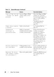
Check the Time and Date settings. Utility partition not available Utility partition is not available on the hard disk Create a utility partition on page 127. 28 About Your System See "Getting Help" on the boot hard drive. No micro code update loaded for processor 0 Micro code update failed. System Messages (continued) Message Causes Corrective...
Check the Time and Date settings. Utility partition not available Utility partition is not available on the hard disk Create a utility partition on page 127. 28 About Your System See "Getting Help" on the boot hard drive. No micro code update loaded for processor 0 Micro code update failed. System Messages (continued) Message Causes Corrective...
Hardware Owner's Manual (PDF)
Page 29
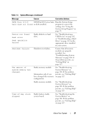
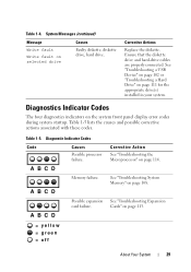
... failure. Corrective Action See "Troubleshooting the Microprocessor" on page 111 for the appropriate drive(s) installed in your system. Corrective Actions Replace the diskette. See "Troubleshooting a USB Device" on page 102 or "Troubleshooting a Hard Drive" on page 114. A B C D Memory failure. A B C D ...on the system front panel display error codes during system startup. See "Troubleshooting Expansion Cards" on selected drive Causes Faulty diskette, diskette drive, hard drive. System Messages (continued) Message Write fault Write fault on page 113. = yellow = green = off...
... failure. Corrective Action See "Troubleshooting the Microprocessor" on page 111 for the appropriate drive(s) installed in your system. Corrective Actions Replace the diskette. See "Troubleshooting a USB Device" on page 102 or "Troubleshooting a Hard Drive" on page 114. A B C D Memory failure. A B C D ...on the system front panel display error codes during system startup. See "Troubleshooting Expansion Cards" on selected drive Causes Faulty diskette, diskette drive, hard drive. System Messages (continued) Message Write fault Write fault on page 113. = yellow = green = off...
Hardware Owner's Manual (PDF)
Page 30
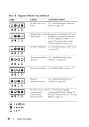
...page 102. system board If the problem persists, see "Getting hardware failure. A B C D A B C D Diskette drive or hard Ensure that the diskette drive and drive failure. hard-drive are properly connected. Possible system board See "Troubleshooting IRQ resource and/or Assignment Conflicts" on page 113. A B C ...See "Troubleshooting System configuration error. Corrective Action See "Troubleshooting Expansion Cards" on page 98. See "Installing a Hard Drive" on page 67 for information on page 108. A B C D No memory modules See "Troubleshooting System detected. Possible USB failure....
...page 102. system board If the problem persists, see "Getting hardware failure. A B C D A B C D Diskette drive or hard Ensure that the diskette drive and drive failure. hard-drive are properly connected. Possible system board See "Troubleshooting IRQ resource and/or Assignment Conflicts" on page 113. A B C ...See "Troubleshooting System configuration error. Corrective Action See "Troubleshooting Expansion Cards" on page 98. See "Installing a Hard Drive" on page 67 for information on page 108. A B C D No memory modules See "Troubleshooting System detected. Possible USB failure....
Hardware Owner's Manual (PDF)
Page 31
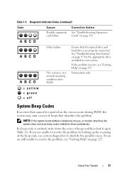
... system is emitted, write down the series of beeps and then look it up the meaning of beeps that the optical drive and hard drives are still unable to resolve the problem by looking up in a normal operating condition after POST. NOTE: If the system... possible cause. See "Troubleshooting Your System" on page 113. About Your System 31 Corrective Action See "Troubleshooting Expansion Cards" on page 97 for the appropriate drive installed in your system. A B C D A B C D A B C D Other failure. If you are unable to resolve the problem, see "Getting Help" on page 127. ...
... system is emitted, write down the series of beeps and then look it up the meaning of beeps that the optical drive and hard drives are still unable to resolve the problem by looking up in a normal operating condition after POST. NOTE: If the system... possible cause. See "Troubleshooting Your System" on page 113. About Your System 31 Corrective Action See "Troubleshooting Expansion Cards" on page 97 for the appropriate drive installed in your system. A B C D A B C D A B C D Other failure. If you are unable to resolve the problem, see "Getting Help" on page 127. ...
Hardware Owner's Manual (PDF)
Page 37
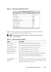
...applicable. System Setup Program Options Option System Time System Date Memory Information CPU Information SATA Configuration Boot Sequence Hard-Disk Drive Sequence Description Resets the time on the hard drives installed in which the system searches the hard drives during system startup. Using the System Setup Program 37 Resets the date on page 39. See "... system. Main System Setup Program Screen Table 2-2 lists the options and descriptions for boot devices during system startup. Available options can include the diskette drive, CD drive, hard drives, and network.
...applicable. System Setup Program Options Option System Time System Date Memory Information CPU Information SATA Configuration Boot Sequence Hard-Disk Drive Sequence Description Resets the time on the hard drives installed in which the system searches the hard drives during system startup. Using the System Setup Program 37 Resets the date on page 39. See "... system. Main System Setup Program Screen Table 2-2 lists the options and descriptions for boot devices during system startup. Available options can include the diskette drive, CD drive, hard drives, and network.
Hardware Owner's Manual (PDF)
Page 38
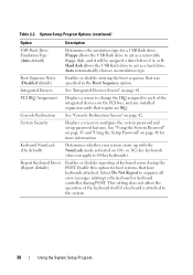
Floppy allows the USB flash drive to act as a hard drive. Auto automatically chooses an emulation type. Integrated Devices See "Integrated Devices Screen" on page 42. Console Redirection See "Console Redirection Screen" on page 41. ... of the integrated devices on 101- System Setup Program Options (continued) Option Description USB Flash Drive Emulation Type (Auto default) Determines the emulation type for more information. Hard disk allows the USB flash drive to the keyboard or keyboard controller during the POST. This setting does not affect the operation of keyboard ...
Floppy allows the USB flash drive to act as a hard drive. Auto automatically chooses an emulation type. Integrated Devices See "Integrated Devices Screen" on page 42. Console Redirection See "Console Redirection Screen" on page 41. ... of the integrated devices on 101- System Setup Program Options (continued) Option Description USB Flash Drive Emulation Type (Auto default) Determines the emulation type for more information. Hard disk allows the USB flash drive to the keyboard or keyboard controller during the POST. This setting does not affect the operation of keyboard ...
Hardware Owner's Manual (PDF)
Page 40
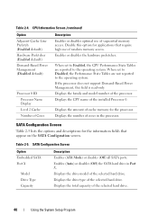
... for applications that appear on the SATA Configuration screen. Enables (Auto) or disables (Off) the SATA hard drive in the processor. Displays the drive model of the selected hard drive. 40 Using the System Setup Program Table 2-4. Table 2-5. CPU Information Screen (continued) Option Adjacent Cache Line...optimal use of cores in Port X. Displays the number of random memory access. Displays the total capacity of the selected hard drive. When set to Enabled, the CPU Performance State Tables are not reported to the operating system. Displays the CPU name ...
... for applications that appear on the SATA Configuration screen. Enables (Auto) or disables (Off) the SATA hard drive in the processor. Displays the drive model of the selected hard drive. 40 Using the System Setup Program Table 2-4. Table 2-5. CPU Information Screen (continued) Option Adjacent Cache Line...optimal use of cores in Port X. Displays the number of random memory access. Displays the total capacity of the selected hard drive. When set to Enabled, the CPU Performance State Tables are not reported to the operating system. Displays the CPU name ...

Hardware Owner's Manual (PDF)
Page 51
Installing System Components This section describes how to install the following system components: • Cooling shroud • System battery • Optical drive • Hard drives • Fan assembly • Optional PCI fan • Power supply • Expansion cards • Riser card • System memory • Processor • Control panel • ...
Installing System Components This section describes how to install the following system components: • Cooling shroud • System battery • Optical drive • Hard drives • Fan assembly • Optional PCI fan • Power supply • Expansion cards • Riser card • System memory • Processor • Control panel • ...


