Information Update - Intel Xeon 5600 Series Processors
Page 2
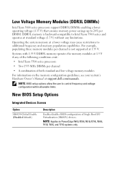
... Voltage Memory Modules (DDR3L DIMMs) Intel Xeon 5600 series processors support DDR3L DIMMs enabling a lower operating voltage (1.35 V) that ensures memory power savings up to 20% per channel • A combination of both standard and low voltage memory modules For information on the memory configuration guidelines, see your system's Hardware Owner's Manual at support.dell.com/manuals...
... Voltage Memory Modules (DDR3L DIMMs) Intel Xeon 5600 series processors support DDR3L DIMMs enabling a lower operating voltage (1.35 V) that ensures memory power savings up to 20% per channel • A combination of both standard and low voltage memory modules For information on the memory configuration guidelines, see your system's Hardware Owner's Manual at support.dell.com/manuals...
Information Update - Intel Xeon 5600 Series Processors
Page 3
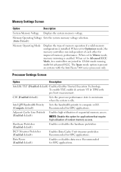
... Bandwidth Priority (Compute default) Sets the bandwidth priority to Optimizer mode, the memory controllers run independent of memory operation if a valid memory configuration is enabled. When set to Mirror mode, memory mirroring is installed. Memory Operating Voltage Sets the system memory voltage selection. (Auto Default) Memory Operating Mode Displays the type of each other for HPC applications. When...
... Bandwidth Priority (Compute default) Sets the bandwidth priority to Optimizer mode, the memory controllers run independent of memory operation if a valid memory configuration is enabled. When set to Mirror mode, memory mirroring is installed. Memory Operating Voltage Sets the system memory voltage selection. (Auto Default) Memory Operating Mode Displays the type of each other for HPC applications. When...
Information Update
Page 4
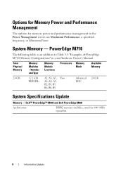
..., B9 Advanced 24 GB ECC System Specifications Update Memory - System Memory - Dell™ PowerEdge™ M905 and Dell PowerEdge M805 Architecture DDR2 memory modules, rated for memory power and performance management in your Hardware Owner's Manual. Total Physical Memory Memory Modules - PowerEdge M710 The following table is an addition to Table 3-5 "Examples of PowerEdge M710 Memory Configurations" in the Power Management screen are Maximum...
..., B9 Advanced 24 GB ECC System Specifications Update Memory - System Memory - Dell™ PowerEdge™ M905 and Dell PowerEdge M805 Architecture DDR2 memory modules, rated for memory power and performance management in your Hardware Owner's Manual. Total Physical Memory Memory Modules - PowerEdge M710 The following table is an addition to Table 3-5 "Examples of PowerEdge M710 Memory Configurations" in the Power Management screen are Maximum...
Hardware Owner's Manual
Page 100
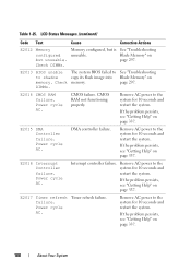
...cycle AC. Interrupt controller failure. Timer refresh failure. CMOS RAM not functioning properly. E2015 DMA Controller failure. Check DIMMs. Memory configured, but unusable. Check DIMMs. The system BIOS failed to the system for 10 seconds and restart the system. If the ... AC power to the system for 10 seconds and restart the system. LCD Status Messages (continued) Code Text Cause Corrective Actions E2012 Memory configured but is unusable. If the problem persists, see "Getting Help" on page 337. Power cycle AC. If the problem persists, ...
...cycle AC. Interrupt controller failure. Timer refresh failure. CMOS RAM not functioning properly. E2015 DMA Controller failure. Check DIMMs. Memory configured, but unusable. Check DIMMs. The system BIOS failed to the system for 10 seconds and restart the system. If the ... AC power to the system for 10 seconds and restart the system. LCD Status Messages (continued) Code Text Cause Corrective Actions E2012 Memory configured but is unusable. If the problem persists, see "Getting Help" on page 337. Power cycle AC. If the problem persists, ...
Hardware Owner's Manual
Page 102
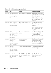
...power to the system for specific error messages. failure. Incorrect memory configuration. LCD Status Messages (continued) Code Text Cause Corrective Actions E201D Shutdown test failure. E2020 CPU Processor configuration configuration failure. Check screen message. Review User Guide. Check screen message...(see "Getting Help" on page 337. See "Troubleshooting Blade Memory" on page 337. If the problem persists, see "Troubleshooting Blade Memory" on page 300. failure. E2021 Incorrect memory configuration. If the problem persists, see "Getting Help" on page 297...
...power to the system for specific error messages. failure. Incorrect memory configuration. LCD Status Messages (continued) Code Text Cause Corrective Actions E201D Shutdown test failure. E2020 CPU Processor configuration configuration failure. Check screen message. Review User Guide. Check screen message...(see "Getting Help" on page 337. See "Troubleshooting Blade Memory" on page 337. If the problem persists, see "Troubleshooting Blade Memory" on page 300. failure. E2021 Incorrect memory configuration. If the problem persists, see "Getting Help" on page 297...
Hardware Owner's Manual
Page 108
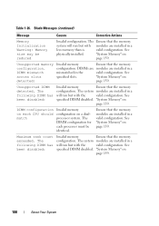
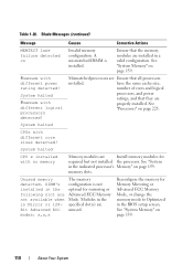
... system modules are installed in the valid configuration. The following DIMM has been disabled: Invalid memory Ensure that the memory system will run but with the valid configuration. Unsupported DIMM detected. "System Memory" on page 159. DIMM configuration on each processor must be reduced Invalid configuration. Ensure that the memory configuration. Table 1-26. See specified DIMM disabled. The system...
... system modules are installed in the valid configuration. The following DIMM has been disabled: Invalid memory Ensure that the memory system will run but with the valid configuration. Unsupported DIMM detected. "System Memory" on page 159. DIMM configuration on each processor must be reduced Invalid configuration. Ensure that the memory configuration. Table 1-26. See specified DIMM disabled. The system...
Hardware Owner's Manual
Page 109
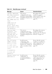
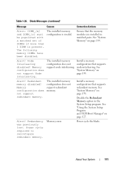
... and geometry: Thermal sensor not detected on disabled. The memory Reconfigure the memory configuration does not modules for Memory match the setting in BIOS. in geometry: in pairs. The memory Reconfigure the memory configuration does not modules to support match the setting in BIOS....DIMM's should match in size: in rank count: in a valid configuration. About Your System 109 Ensure that the memory modules are installed in size and rank count: Invalid memory configuration. See "System Memory" on page 159. Table 1-26. Blade Messages (continued) Message...
... and geometry: Thermal sensor not detected on disabled. The memory Reconfigure the memory configuration does not modules for Memory match the setting in BIOS. in geometry: in pairs. The memory Reconfigure the memory configuration does not modules to support match the setting in BIOS....DIMM's should match in size: in rank count: in a valid configuration. About Your System 109 Ensure that the memory modules are installed in size and rank count: Invalid memory configuration. See "System Memory" on page 159. Table 1-26. Blade Messages (continued) Message...
Hardware Owner's Manual
Page 110
... in the BIOS setup screen. See "System Memory" on Invalid memory configuration. System halted CPU x installed with different core sizes detected! Reconfigure the memory for Memory Mirroring or Advanced ECC Memory Mode, or change the memory mode to Optimized in the indicated processor's Memory" on page 159. Ensure that the memory modules are installed in the specified slot(s) are...
... in the BIOS setup screen. See "System Memory" on Invalid memory configuration. System halted CPU x installed with different core sizes detected! Reconfigure the memory for Memory Mirroring or Advanced ECC Memory Mode, or change the memory mode to Optimized in the indicated processor's Memory" on page 159. Ensure that the memory modules are installed in the specified slot(s) are...
Hardware Owner's Manual
Page 111
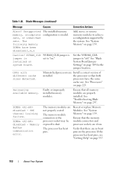
... more than 1 DIMM is invalid. Node Interleaving disabled! See "System Memory" on page 159. Redundancy was previously lost. node interleaving. Memory error. The installed memory configuration is present. Alert! About Your System 111 Memory configuration does not support Node Interleaving. Memory configuration does not support redundant memory. Ensure that the memory modules are installed in the System Setup program. Redundant...
... more than 1 DIMM is invalid. Node Interleaving disabled! See "System Memory" on page 159. Redundancy was previously lost. node interleaving. Memory error. The installed memory configuration is present. Alert! About Your System 111 Memory configuration does not support Node Interleaving. Memory configuration does not support redundant memory. Ensure that the memory modules are installed in the System Setup program. Redundant...
Hardware Owner's Manual
Page 112
... Jumper Settings" on page 337. 112 About Your System the processor so that all memory modules are properly installed. Faulty or improperly installed memory modules. Ensure that both processors have been disabled:l,m,n The installed memory configuration is installed on the processor. Memory Buffer communication error. If the processor has bent pins, see "Getting Help" on...
... Jumper Settings" on page 337. 112 About Your System the processor so that all memory modules are properly installed. Faulty or improperly installed memory modules. Ensure that both processors have been disabled:l,m,n The installed memory configuration is installed on the processor. Memory Buffer communication error. If the processor has bent pins, see "Getting Help" on...
Hardware Owner's Manual
Page 115
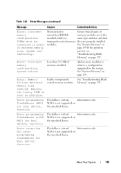
... Messages (continued) Message Causes Corrective Actions Error: Incorrect memory configuration. Mismatched or Ensure that improperly seated memory they are of unmatched DIMMs memory modules are properly installed. Error: Memory failure detected. Error resetting NIC after programming flexAddress for bus...(virtual Information only. DIMMs must be installed in pairs of memory installed. Error: Incorrect memory configuration. MAC) is not supported on page 297. See "Troubleshooting Blade Memory" on the specified device. FlexAddress (virtual Information only. MAC)...
... Messages (continued) Message Causes Corrective Actions Error: Incorrect memory configuration. Mismatched or Ensure that improperly seated memory they are of unmatched DIMMs memory modules are properly installed. Error: Memory failure detected. Error resetting NIC after programming flexAddress for bus...(virtual Information only. DIMMs must be installed in pairs of memory installed. Error: Incorrect memory configuration. MAC) is not supported on page 297. See "Troubleshooting Blade Memory" on the specified device. FlexAddress (virtual Information only. MAC)...

Hardware Owner's Manual
Page 123
... not an intentional setting, check any key to The memory frequency minimum frequency. "System Memory" on page 297. Warning! See "Troubleshooting Blade Memory" on page 159. Warning: The current memory configuration is not recommended by Dell. the memory configuration is not validated. Blade Messages (continued) Message Causes Corrective Actions Memory set lower for power conservation. See frequency. Following faulty...
... not an intentional setting, check any key to The memory frequency minimum frequency. "System Memory" on page 297. Warning! See "Troubleshooting Blade Memory" on page 159. Warning: The current memory configuration is not recommended by Dell. the memory configuration is not validated. Blade Messages (continued) Message Causes Corrective Actions Memory set lower for power conservation. See frequency. Following faulty...

Hardware Owner's Manual
Page 124
Faulty diskette, diskette drive, or optical drive. Ensure that you to respond by Dell. the memory configuration is properly connected. "Troubleshooting Blade Memory" on selected drive. A warning message alerts you to a possible problem and prompts you to respond before... you may lose all data on valid memory configurations, please see the Glossary at support.dell.com/manuals. For more information on the diskette. Table 1-26. Blade Messages (continued) Message Causes Corrective Actions Warning: The current memory configuration is no ). 124 About Your System...
Faulty diskette, diskette drive, or optical drive. Ensure that you to respond by Dell. the memory configuration is properly connected. "Troubleshooting Blade Memory" on selected drive. A warning message alerts you to a possible problem and prompts you to respond before... you may lose all data on valid memory configurations, please see the Glossary at support.dell.com/manuals. For more information on the diskette. Table 1-26. Blade Messages (continued) Message Causes Corrective Actions Warning: The current memory configuration is no ). 124 About Your System...
Hardware Owner's Manual
Page 130
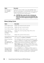
... Memory Voltage (PowerEdge M710HD) Displays the current operating voltage of system memory. System Memory Testing Specifies whether system memory tests are run in 64-bit mode, and memory performance is installed. If set to Enabled, the memory controllers operate independently in parallel 64-bit mode for improved memory performance. System Memory Type Displays the type of memory operation if a valid memory configuration...
... Memory Voltage (PowerEdge M710HD) Displays the current operating voltage of system memory. System Memory Testing Specifies whether system memory tests are run in 64-bit mode, and memory performance is installed. If set to Enabled, the memory controllers operate independently in parallel 64-bit mode for improved memory performance. System Memory Type Displays the type of memory operation if a valid memory configuration...

Hardware Owner's Manual
Page 131
Redundant Memory (PowerEdge M910, M905, M805, and M605) If a valid memory configuration is employed. Options are Mirror Mode, Spare Mode, and Disabled. Displays the bus speed of the processors. Displays when the ...with Intel® Xeon® 5600 series processors support memory sparing. This feature can enable memory mirroring or spare memory. If Enabled, memory interleaving is enabled. Options are Spare Mode and Disabled. Option Description Redundant Memory (PowerEdge M910, M710HD, and M600) If a valid memory configuration is installed, you can also set to Disabled, ...
Redundant Memory (PowerEdge M910, M905, M805, and M605) If a valid memory configuration is employed. Options are Mirror Mode, Spare Mode, and Disabled. Displays the bus speed of the processors. Displays when the ...with Intel® Xeon® 5600 series processors support memory sparing. This feature can enable memory mirroring or spare memory. If Enabled, memory interleaving is enabled. Options are Spare Mode and Disabled. Option Description Redundant Memory (PowerEdge M910, M710HD, and M600) If a valid memory configuration is installed, you can also set to Disabled, ...
Hardware Owner's Manual
Page 159
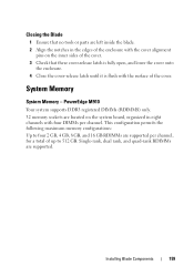
PowerEdge M910 Your system supports DDR3 registered DIMMs (RDIMMS) only. 32 memory sockets are located on the inner sides of the cover. 3 Check that no tools or parts are left inside the blade. 2 Align the notches in ... the system board, organized in eight channels with the surface of up to 512 GB. This configuration permits the following maximum memory configurations: Up to four 2 GB, 4 GB, 8 GB, and 16 GB RDIMMs are supported. System Memory System Memory - Closing the Blade 1 Ensure that these cover-release latch is fully open, and lower the cover...
PowerEdge M910 Your system supports DDR3 registered DIMMs (RDIMMS) only. 32 memory sockets are located on the inner sides of the cover. 3 Check that no tools or parts are left inside the blade. 2 Align the notches in ... the system board, organized in eight channels with the surface of up to 512 GB. This configuration permits the following maximum memory configurations: Up to four 2 GB, 4 GB, 8 GB, and 16 GB RDIMMs are supported. System Memory System Memory - Closing the Blade 1 Ensure that these cover-release latch is fully open, and lower the cover...
Hardware Owner's Manual
Page 161
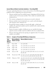
These sockets are marked by white retention levers. • The memory configuration for each set of PowerEdge M910 Memory Configurations Total Physical Memory 4 GB 8 GB 16 GB 32 GB 64 GB 96 GB 128 GB 128 GB Memory Modules - Memory Module Locations Number and Type Four 1 GB A1, A2, B1, B2 Eight 1 GB A1, A2, B1, B2, C1, C2...
These sockets are marked by white retention levers. • The memory configuration for each set of PowerEdge M910 Memory Configurations Total Physical Memory 4 GB 8 GB 16 GB 32 GB 64 GB 96 GB 128 GB 128 GB Memory Modules - Memory Module Locations Number and Type Four 1 GB A1, A2, B1, B2 Eight 1 GB A1, A2, B1, B2, C1, C2...
Hardware Owner's Manual
Page 162
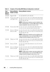
..., D1, D2, D3, D4, D5, D6, D7, D8 NOTE: 8-GB memory modules must be installed in the lower numbered slots x1, x2 and 4-GB memory modules must be installed in slots x5, x6, x7, x8. Table 3-1. Examples of PowerEdge M910 Memory Configurations (continued) Total Physical Memory 128 GB 160 GB 192 GB 192 GB 256 GB... 256 GB 384 GB 512 GB Memory Modules - Twenty-four 8 GB A1, A2, A3, A4, A5, A6, B1, B2, B3, B4, B5, B6, C1, ...
..., D1, D2, D3, D4, D5, D6, D7, D8 NOTE: 8-GB memory modules must be installed in the lower numbered slots x1, x2 and 4-GB memory modules must be installed in slots x5, x6, x7, x8. Table 3-1. Examples of PowerEdge M910 Memory Configurations (continued) Total Physical Memory 128 GB 160 GB 192 GB 192 GB 256 GB... 256 GB 384 GB 512 GB Memory Modules - Twenty-four 8 GB A1, A2, A3, A4, A5, A6, B1, B2, B3, B4, B5, B6, C1, ...
Hardware Owner's Manual
Page 163
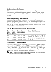
...) is supported in systems that your memory configuration is nonoptimal. Table 3-2. Memory Sparing Configurations - The memory sparing feature must disable node interleaving. Your system may issue an error message during start-up to twenty-four 667 MHz registered DDR2 memory modules in sets of two channels. PowerEdge M910 Total System Memory 128 GB 256 GB 512 GB Usable...
...) is supported in systems that your memory configuration is nonoptimal. Table 3-2. Memory Sparing Configurations - The memory sparing feature must disable node interleaving. Your system may issue an error message during start-up to twenty-four 667 MHz registered DDR2 memory modules in sets of two channels. PowerEdge M910 Total System Memory 128 GB 256 GB 512 GB Usable...
Hardware Owner's Manual
Page 165
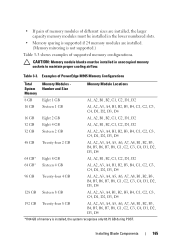
...installed, the system recognizes only 63.75 GB during POST. Installing Blade Components 165 Table 3-3. Examples of PowerEdge M905 Memory Configurations Total System Memory Memory Modules Number and Size Memory Module Locations 8 GB Eight 1 GB A1, A2, B1, B2, C1, C2, D1, D2 ...If 64 GB of supported memory configurations. CAUTION: Memory module blanks must be installed in the lower numbered slots. • Memory sparing is supported if 24 memory modules are installed, the larger capacity memory modules must be installed in unoccupied memory sockets to maintain proper cooling ...
...installed, the system recognizes only 63.75 GB during POST. Installing Blade Components 165 Table 3-3. Examples of PowerEdge M905 Memory Configurations Total System Memory Memory Modules Number and Size Memory Module Locations 8 GB Eight 1 GB A1, A2, B1, B2, C1, C2, D1, D2 ...If 64 GB of supported memory configurations. CAUTION: Memory module blanks must be installed in the lower numbered slots. • Memory sparing is supported if 24 memory modules are installed, the larger capacity memory modules must be installed in unoccupied memory sockets to maintain proper cooling ...


