Getting Started Guide
Page 5
One Intel Pentium® 4, 600 Sequence • A minimum of 512 MB of 533-MHz or 667-MHz DDR2 SDRAM memory, upgradable to view processor information. One full-height, half-length, 133MHz/64 bit PCI-X expansion slot and one full-height, half-length PCIe expansion slot ...-drive configurations: - NOTE: Use the System Setup program to a maximum of 8 GB by installing combinations of 512-MB, 1-GB, or 2-GB unbuffered ECC memory modules in four memory module sockets on the system board. • One of the following riser card options: - Up to two internal, 1-inch high, SATA hard drives with...
One Intel Pentium® 4, 600 Sequence • A minimum of 512 MB of 533-MHz or 667-MHz DDR2 SDRAM memory, upgradable to view processor information. One full-height, half-length, 133MHz/64 bit PCI-X expansion slot and one full-height, half-length PCIe expansion slot ...-drive configurations: - NOTE: Use the System Setup program to a maximum of 8 GB by installing combinations of 512-MB, 1-GB, or 2-GB unbuffered ECC memory modules in four memory module sockets on the system board. • One of the following riser card options: - Up to two internal, 1-inch high, SATA hard drives with...
Getting Started Guide
Page 6
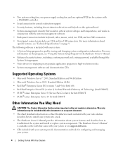
...• Red Hat® Enterprise Linux ES (versions 3 and 4) for Intel x86 • Red Hat Enterprise Linux ES (version 4) for Intel Extended Memory 64 Technology (Intel EM64T) • SUSE® Linux Enterprise Server 9 (Service Pack 2 or later) for Intel EM64T • SUSE® Linux ... System • Two system cooling fans, one power-supply cooling fan, and one VGA and two USB connectors. For more information on support.dell.com. • CDs included with a SAS/RAID controller. • Serial connector for displaying many popular application programs in high-resolution modes....
...• Red Hat® Enterprise Linux ES (versions 3 and 4) for Intel x86 • Red Hat Enterprise Linux ES (version 4) for Intel Extended Memory 64 Technology (Intel EM64T) • SUSE® Linux Enterprise Server 9 (Service Pack 2 or later) for Intel EM64T • SUSE® Linux ... System • Two system cooling fans, one power-supply cooling fan, and one VGA and two USB connectors. For more information on support.dell.com. • CDs included with a SAS/RAID controller. • Serial connector for displaying many popular application programs in high-resolution modes....
Getting Started Guide
Page 12
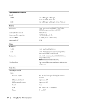
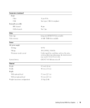
...network adapters) 6-pin mini-DIN 6-pin mini-DIN 9 pin Two 4-pin, USB 2.0 compliant 15-pin VGA Expansion Buses (continued) Riser 2 PCI-X PCIe Memory Architecture Memory module sockets Memory module capacities Minimum RAM Maximum RAM Drives Hard Drives SATA SAS Optical drive USB flash drive Connectors Externally accessible Back Network adapter PS/2-style..., half-length, 64-bit, 133MHz PCI-X slot One full-height, half-length, x8 lane PCIe slot Up to four unbuffered DDR2 533/667 MHz SDRAM memory modules with ECC Four 240-pin 512 MB, 1 GB, or 2 GB 512 MB (one 512-MB module) 8 GB Up to two 1-inch high...
...network adapters) 6-pin mini-DIN 6-pin mini-DIN 9 pin Two 4-pin, USB 2.0 compliant 15-pin VGA Expansion Buses (continued) Riser 2 PCI-X PCIe Memory Architecture Memory module sockets Memory module capacities Minimum RAM Maximum RAM Drives Hard Drives SATA SAS Optical drive USB flash drive Connectors Externally accessible Back Network adapter PS/2-style..., half-length, 64-bit, 133MHz PCI-X slot One full-height, half-length, x8 lane PCIe slot Up to four unbuffered DDR2 533/667 MHz SDRAM memory modules with ECC Four 240-pin 512 MB, 1 GB, or 2 GB 512 MB (one 512-MB module) 8 GB Up to two 1-inch high...
Getting Started Guide
Page 13
Connectors (continued) Front Video USB Internally accessible IDE channel SATA channels Video Video type Video memory Power AC power supply Wattage Voltage Maximum inrush current System battery Physical Height Width Depth With optional bezel Without optional bezel Weight (maximum configuration) 15-...
Connectors (continued) Front Video USB Internally accessible IDE channel SATA channels Video Video type Video memory Power AC power supply Wattage Voltage Maximum inrush current System battery Physical Height Width Depth With optional bezel Without optional bezel Weight (maximum configuration) 15-...
Hardware Owner's Manual (PDF)
Page 5
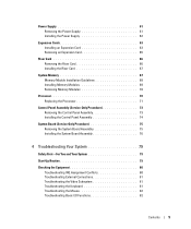
... Card 63 Removing an Expansion Card 65 Riser Card 66 Removing the Riser Card 66 Installing the Riser Card 67 System Memory 67 Memory Module Installation Guidelines 68 Installing Memory Modules 69 Removing Memory Modules 70 Processor 70 Replacing the Processor 71 Control Panel Assembly (Service-Only Procedure 73 Removing the Control Panel Assembly...
... Card 63 Removing an Expansion Card 65 Riser Card 66 Removing the Riser Card 66 Installing the Riser Card 67 System Memory 67 Memory Module Installation Guidelines 68 Installing Memory Modules 69 Removing Memory Modules 70 Processor 70 Replacing the Processor 71 Control Panel Assembly (Service-Only Procedure 73 Removing the Control Panel Assembly...
Hardware Owner's Manual (PDF)
Page 6
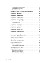
... Power Supply 86 Troubleshooting System Cooling Problems 87 Troubleshooting a Fan 87 Troubleshooting System Memory 88 Troubleshooting an Optical Drive 89 Troubleshooting a Hard Drive 90 Troubleshooting Expansion Cards 91 Troubleshooting the Microprocessor 92 5 Running the System Diagnostics 93 Using Dell PowerEdge Diagnostics 93 System Diagnostics Features 93 When to Use the System Diagnostics 94...
... Power Supply 86 Troubleshooting System Cooling Problems 87 Troubleshooting a Fan 87 Troubleshooting System Memory 88 Troubleshooting an Optical Drive 89 Troubleshooting a Hard Drive 90 Troubleshooting Expansion Cards 91 Troubleshooting the Microprocessor 92 5 Running the System Diagnostics 93 Using Dell PowerEdge Diagnostics 93 System Diagnostics Features 93 When to Use the System Diagnostics 94...
Hardware Owner's Manual (PDF)
Page 16
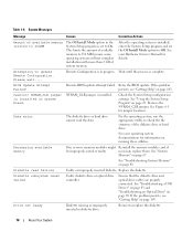
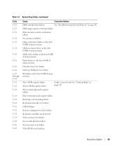
...NVRAM_CLR jumper is complete. See Figure 6-1 for information on page 67. See your Hardware Owner's Manual for details. See "Troubleshooting System Memory" on page 103. Diskette subsystem reset failed Faulty diskette drive or optical drive controller. Reinsert or replace the diskette. 16 About Your... are properly connected. Data error The diskette drive or hard drive cannot read failure Faulty or improperly inserted diskette. Decreasing available memory One or more than 2 GB of the diskette drive or hard drive. See your operating system documentation for jumper locations....
...NVRAM_CLR jumper is complete. See Figure 6-1 for information on page 67. See your Hardware Owner's Manual for details. See "Troubleshooting System Memory" on page 103. Diskette subsystem reset failed Faulty diskette drive or optical drive controller. Reinsert or replace the diskette. 16 About Your... are properly connected. Data error The diskette drive or hard drive cannot read failure Faulty or improperly inserted diskette. Decreasing available memory One or more than 2 GB of the diskette drive or hard drive. See your operating system documentation for jumper locations....
Hardware Owner's Manual (PDF)
Page 17
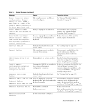
...failed. faulty mouse or persists, replace the keyboard. Faulty system board. Manufacturing mode detected System is properly installed. Invalid memory configuration detected. Verify that the keyboard is unable to correct the settings. Replace the keyboard. See "Getting Help" on ...page 103. System Messages (continued) Message Causes Corrective Actions Error: Incorrect memory configuration. Ensure that the RAC is incorrectly configured. See "Troubleshooting Expansion Cards" on page 67 for data corruption exists...
...failed. faulty mouse or persists, replace the keyboard. Faulty system board. Manufacturing mode detected System is properly installed. Invalid memory configuration detected. Verify that the keyboard is unable to correct the settings. Replace the keyboard. See "Getting Help" on ...page 103. System Messages (continued) Message Causes Corrective Actions Error: Incorrect memory configuration. Ensure that the RAC is incorrectly configured. See "Troubleshooting Expansion Cards" on page 67 for data corruption exists...

Hardware Owner's Manual (PDF)
Page 18
... in the drive. ensure that a bootable disk is your operating system documentation for details. See your boot device, ensure that all memory modules are modules, or faulty system board. information for details. If the problem persists, see "Getting Help" on page 88.... properly installed. See "Troubleshooting System Memory" on page 103. No timer tick interrupt A chip on page 93. 18 About Your System See malfunctioning. See your boot device,...
... in the drive. ensure that a bootable disk is your operating system documentation for details. See your boot device, ensure that all memory modules are modules, or faulty system board. information for details. If the problem persists, see "Getting Help" on page 88.... properly installed. See "Troubleshooting System Memory" on page 103. No timer tick interrupt A chip on page 93. 18 About Your System See malfunctioning. See your boot device,...
Hardware Owner's Manual (PDF)
Page 20
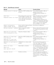
... properly installed. Ensure that the hard drive cables are properly connected. Run the System Setup program to correct the settings. See "Troubleshooting System Memory" on page 90. SATA port 0/1 hard disk drive failure SATA port 0/1 hard disk drive auto-sensing error Faulty drive. See "Using...defective. Shutdown failure Shutdown test failure. Read fault The operating system cannot read Requested sector not found from the drive. Ensure that all memory modules are properly connected. SATA Port 0/1 hard disk not SATA Port0/1 set as Auto, no disk found Seek error Seek operation ...
... properly installed. Ensure that the hard drive cables are properly connected. Run the System Setup program to correct the settings. See "Troubleshooting System Memory" on page 90. SATA port 0/1 hard disk drive failure SATA port 0/1 hard disk drive auto-sensing error Faulty drive. See "Using...defective. Shutdown failure Shutdown test failure. Read fault The operating system cannot read Requested sector not found from the drive. Ensure that all memory modules are properly connected. SATA Port 0/1 hard disk not SATA Port0/1 set as Auto, no disk found Seek error Seek operation ...
Hardware Owner's Manual (PDF)
Page 21
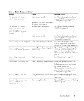
... 2 failed Unexpected interrupt in protected mode Utility partition not available Warning! Information only, if you have changed . See "Troubleshooting System Memory" on page 103. faulty system board. faulty Check the Time and Date settings. If the problem persists, see "Getting Help" ... persists, see "Troubleshooting the System Battery" on page 103. See "Getting Help" on page 68. Invalid memory configuration. See "Memory Module Installation Guidelines" on page 103. properly installed. Utility partition is below the minimum system configuration. See "Troubleshooting System...
... 2 failed Unexpected interrupt in protected mode Utility partition not available Warning! Information only, if you have changed . See "Troubleshooting System Memory" on page 103. faulty system board. faulty Check the Time and Date settings. If the problem persists, see "Getting Help" ... persists, see "Troubleshooting the System Battery" on page 103. See "Getting Help" on page 68. Invalid memory configuration. See "Memory Module Installation Guidelines" on page 103. properly installed. Utility partition is below the minimum system configuration. See "Troubleshooting System...
Hardware Owner's Manual (PDF)
Page 22
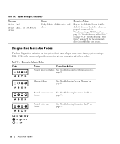
... drive Causes Faulty diskette, diskette drive, hard drive. Table 1-5 lists the causes and possible corrective actions associated with these codes. A B C D Memory failure. See "Troubleshooting the Microprocessor" on page 88. See "Troubleshooting System Memory" on page 92. A B C D A B C D A B C D Possible expansion card See "Troubleshooting Expansion Cards" on page 91. = yellow = green = off 22 About Your...
... drive Causes Faulty diskette, diskette drive, hard drive. Table 1-5 lists the causes and possible corrective actions associated with these codes. A B C D Memory failure. See "Troubleshooting the Microprocessor" on page 88. See "Troubleshooting System Memory" on page 92. A B C D A B C D A B C D Possible expansion card See "Troubleshooting Expansion Cards" on page 91. = yellow = green = off 22 About Your...

Hardware Owner's Manual (PDF)
Page 23
...Help" on page 103. See "Installing a Hard Drive" on the drives installed in your system. A B C D No memory modules detected. Possible expansion card See "Troubleshooting Expansion Cards" on page 103. Ensure that the diskette drive and hard-drive are ... hard drives are properly connected. A B C D A B C D A B C D A B C D A B C D = yellow = green = off Memory configuration See "Troubleshooting System Memory" on page 83. Diagnostic Indicator Codes (continued) Code A B C D Causes Diskette drive or hard drive failure. See "Troubleshooting IRQ Assignment Conflicts" on page 88...
...Help" on page 103. See "Installing a Hard Drive" on the drives installed in your system. A B C D No memory modules detected. Possible expansion card See "Troubleshooting Expansion Cards" on page 103. Ensure that the diskette drive and hard-drive are ... hard drives are properly connected. A B C D A B C D A B C D A B C D A B C D = yellow = green = off Memory configuration See "Troubleshooting System Memory" on page 83. Diagnostic Indicator Codes (continued) Code A B C D Causes Diskette drive or hard drive failure. See "Troubleshooting IRQ Assignment Conflicts" on page 88...
Hardware Owner's Manual (PDF)
Page 25
... failure Slave interrupt-mask register failure Interrupt vector loading failure Keyboard-controller test failure CMOS failure System configuration check failure Keyboard controller not detected Video memory test failure Screen initialization failure Screen-retrace test failure Video ROM search failure About Your System 25 System Beep Codes (continued) Code 1-2-2 1-2-3 1-3-1 1-3-2 1-3-3 1-3-4 1-4-1 1-4-2 1-4-3 1-4-4 2-1-1 through 2-4-4 3-1-1 3-1-2 3-1-3 3-1-4 3-2-2 3-2-4 3-3-1 3-3-2 3-3-3 3-3-4 3-4-1 3-4-2 3-4-3 Cause Corrective...
... failure Slave interrupt-mask register failure Interrupt vector loading failure Keyboard-controller test failure CMOS failure System configuration check failure Keyboard controller not detected Video memory test failure Screen initialization failure Screen-retrace test failure Video ROM search failure About Your System 25 System Beep Codes (continued) Code 1-2-2 1-2-3 1-3-1 1-3-2 1-3-3 1-3-4 1-4-1 1-4-2 1-4-3 1-4-4 2-1-1 through 2-4-4 3-1-1 3-1-2 3-1-3 3-1-4 3-2-2 3-2-4 3-3-1 3-3-2 3-3-3 3-3-4 3-4-1 3-4-2 3-4-3 Cause Corrective...

Hardware Owner's Manual (PDF)
Page 26
Improperly installed or faulty memory modules See "Troubleshooting System Memory" on page 103. No memory modules installed in the Install a memory module in this section. If the problem persists, see the documentation that accompanied the operating system or application. Cache ..., before the system continues a task. NOTE: Warning messages are not covered in the first memory first memory module connector module connector. Record the message on a copy of -day clock stopped See "Troubleshooting System Memory" on mode page 91. See "Getting Help" on page 92. Super I/O chip failure...
Improperly installed or faulty memory modules See "Troubleshooting System Memory" on page 103. No memory modules installed in the Install a memory module in this section. If the problem persists, see the documentation that accompanied the operating system or application. Cache ..., before the system continues a task. NOTE: Warning messages are not covered in the first memory first memory module connector module connector. Record the message on a copy of -day clock stopped See "Troubleshooting System Memory" on mode page 91. See "Getting Help" on page 92. Super I/O chip failure...
Hardware Owner's Manual (PDF)
Page 29
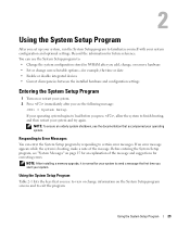
... yourself with your operating system. Responding to Error Messages You can use to view or change user-selectable options-for future reference. NOTE: After installing a memory upgrade, it is booting, make a note of the message and suggestions for your system to certain error messages. Before entering the System Setup program, see...
... yourself with your operating system. Responding to Error Messages You can use to view or change user-selectable options-for future reference. NOTE: After installing a memory upgrade, it is booting, make a note of the message and suggestions for your system to certain error messages. Before entering the System Setup program, see...
Hardware Owner's Manual (PDF)
Page 31
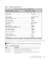
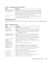
Using the System Setup Program 31 Resets the date on the system's internal clock. Table 2-2. System Setup Program Options Option System Time System Date System Memory Description Resets the time on the system's internal calendar. This option does not have userselectable settings. NOTE: The System Setup program defaults are listed under ... Screen Table 2-2 lists the options and descriptions for the information fields that appear on the main System Setup program screen. Displays the amount of system memory.
Using the System Setup Program 31 Resets the date on the system's internal clock. Table 2-2. System Setup Program Options Option System Time System Date System Memory Description Resets the time on the system's internal calendar. This option does not have userselectable settings. NOTE: The System Setup program defaults are listed under ... Screen Table 2-2 lists the options and descriptions for the information fields that appear on the main System Setup program screen. Displays the amount of system memory.
Hardware Owner's Manual (PDF)
Page 32
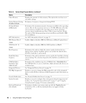
... operating system. Auto automatically chooses an emulation type. Determines whether your system. Determines the maximum amount of the system memory available to 256 MB. Determines the order in which the system searches the hard drives during system startup. Determines the...and network. Displays a screen to 84-key keyboards). 32 Using the System Setup Program Table 2-2. System Setup Program Options (continued) Option Video Memory System Memory Testing (Enabled default) OS Install Mode (Off default) CPU Information IDE Primary Drive 0 (Auto) SATA Port (0 - 1) (Auto) Boot...
... operating system. Auto automatically chooses an emulation type. Determines whether your system. Determines the maximum amount of the system memory available to 256 MB. Determines the order in which the system searches the hard drives during system startup. Determines the...and network. Displays a screen to 84-key keyboards). 32 Using the System Setup Program Table 2-2. System Setup Program Options (continued) Option Video Memory System Memory Testing (Enabled default) OS Install Mode (Off default) CPU Information IDE Primary Drive 0 (Auto) SATA Port (0 - 1) (Auto) Boot...
Hardware Owner's Manual (PDF)
Page 33
... Management (Disabled default) When set to Disabled, the Performance State Tables are reported to be used by software that require high use of random memory access. When set to Enabled, the CPU Performance State Tables are not reported to the keyboard or keyboard controller during the POST. Level 2... the processor. System Setup Program Options (continued) Option Report Keyboard Errors (Report default) Asset Tag Description Enables or disables reporting of cache memory for the system if an asset tag number has been assigned. This setting does not affect the operation of sequential...
... Management (Disabled default) When set to Disabled, the Performance State Tables are reported to be used by software that require high use of random memory access. When set to Enabled, the CPU Performance State Tables are not reported to the keyboard or keyboard controller during the POST. Level 2... the processor. System Setup Program Options (continued) Option Report Keyboard Errors (Report default) Asset Tag Description Enables or disables reporting of cache memory for the system if an asset tag number has been assigned. This setting does not affect the operation of sequential...
Hardware Owner's Manual (PDF)
Page 43
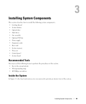
... battery • Optical drive • Hard drives • Fan assembly • Optional PCI fan • Power supply • Expansion cards • Riser card • System memory • Processor • Control panel • System board Recommended Tools You may need the following items to perform the procedures in this section: • Key...
... battery • Optical drive • Hard drives • Fan assembly • Optional PCI fan • Power supply • Expansion cards • Riser card • System memory • Processor • Control panel • System board Recommended Tools You may need the following items to perform the procedures in this section: • Key...


