Microprocessor Upgrade Installation Guide
Page 3
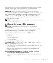
Each microprocessor and its associated cache memory are included in the System Information document. 3 Remove the cooling shroud, if applicable (see your Installation and Troubleshooting Guide). CAUTION: See "Protecting Against Electrostatic Discharge... socket. NOTE: In a single microprocessor system, the microprocessor must be present to install or replace the microprocessor in a ZIF socket on the Dell Support website at support.dell.com, and upgrade the BIOS if necessary. The following items are contained in a pin-grid array (PGA) package that is installed in either...
Each microprocessor and its associated cache memory are included in the System Information document. 3 Remove the cooling shroud, if applicable (see your Installation and Troubleshooting Guide). CAUTION: See "Protecting Against Electrostatic Discharge... socket. NOTE: In a single microprocessor system, the microprocessor must be present to install or replace the microprocessor in a ZIF socket on the Dell Support website at support.dell.com, and upgrade the BIOS if necessary. The following items are contained in a pin-grid array (PGA) package that is installed in either...
Microprocessor Upgrade Installation Guide
Page 7
... system startup. NOTE: After you access the inside of the new processor and automatically changes the system configuration information in the system's nonvolatile random-access memory (NVRAM). Microprocessor Upgrade Installation Guide 1-5 For instructions about running the diagnostics and troubleshooting any problems that may occur. As the system boots, it detects the...
... system startup. NOTE: After you access the inside of the new processor and automatically changes the system configuration information in the system's nonvolatile random-access memory (NVRAM). Microprocessor Upgrade Installation Guide 1-5 For instructions about running the diagnostics and troubleshooting any problems that may occur. As the system boots, it detects the...
Information Update — 1-GB 512-Mb Memory Modules
Page 1
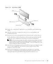
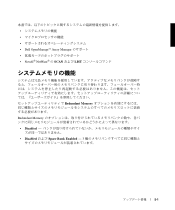
...See Figure 1 to ensure that have a no POST/no video error condition. These two technologies are not interchangeable within a memory module bank, your Installation and Troubleshooting Guide for complete information about safety precautions, working inside the computer, and protecting against ...same memory module technology. July 2004 However, the mixing of 256 Mb and 512 Mb technologies will have redundant memory features (spare bank, memory mirroring, and enhanced memory mapping) to 512-Mb technology for property damage, personal injury, or death. www.dell.com | support.dell.com ...
...See Figure 1 to ensure that have a no POST/no video error condition. These two technologies are not interchangeable within a memory module bank, your Installation and Troubleshooting Guide for complete information about safety precautions, working inside the computer, and protecting against ...same memory module technology. July 2004 However, the mixing of 256 Mb and 512 Mb technologies will have redundant memory features (spare bank, memory mirroring, and enhanced memory mapping) to 512-Mb technology for property damage, personal injury, or death. www.dell.com | support.dell.com ...
Information Update — 1-GB 512-Mb Memory Modules
Page 2
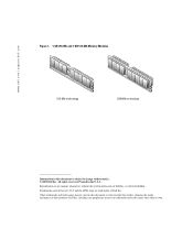
... products. disclaims any manner whatsoever without notice. © 2004 Dell Inc. Other trademarks and trade names may be used in this text: Dell and the DELL logo are trademarks of Dell Inc. www.dell.com | support.dell.com Figure 1. 1-GB 256-Mb and 1-GB 512-Mb Memory Modules 512-Mb technology 256-Mb technology Information in this...
... products. disclaims any manner whatsoever without notice. © 2004 Dell Inc. Other trademarks and trade names may be used in this text: Dell and the DELL logo are trademarks of Dell Inc. www.dell.com | support.dell.com Figure 1. 1-GB 256-Mb and 1-GB 512-Mb Memory Modules 512-Mb technology 256-Mb technology Information in this...
Information Update
Page 9
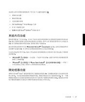
• • • • Dell OpenManage™ Array Manager • • SCAN LIST Novell® NetWare® Redundant Memory • Disabled - • Disabled Spare Bank Enabled - Intel® Xeon™ 2-1
• • • • Dell OpenManage™ Array Manager • • SCAN LIST Novell® NetWare® Redundant Memory • Disabled - • Disabled Spare Bank Enabled - Intel® Xeon™ 2-1
Information Update
Page 27
• • • • Dell OpenManage™ Array Manager • • Novell® NetWare® SCAN LIST Redundant Memory Redundant Memory • Disabled - • Disabled Spare Bank Enabled - 3 5-1
• • • • Dell OpenManage™ Array Manager • • Novell® NetWare® SCAN LIST Redundant Memory Redundant Memory • Disabled - • Disabled Spare Bank Enabled - 3 5-1
Removing the Back Fan Assembly
Page 1
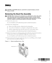
...and Troubleshooting Guide for detailed information. 2 Remove the cooling shroud. See your System Information Guide for detailed information. 3 Remove the memory riser cards by grasping each card by squeezing the fan release levers and lifting each fan straight up to the system. c Lift... and the chassis. See your Installation and Troubleshooting Guide for complete information about safety precautions, working inside the system. www.dell.com | support.dell.com CAUTION: A CAUTION indicates a potential for detailed information. 4 Remove the four fans by the extractor tabs, located ...
...and Troubleshooting Guide for detailed information. 2 Remove the cooling shroud. See your System Information Guide for detailed information. 3 Remove the memory riser cards by grasping each card by squeezing the fan release levers and lifting each fan straight up to the system. c Lift... and the chassis. See your Installation and Troubleshooting Guide for complete information about safety precautions, working inside the system. www.dell.com | support.dell.com CAUTION: A CAUTION indicates a potential for detailed information. 4 Remove the four fans by the extractor tabs, located ...
Removing the Back Fan Assembly
Page 3
... system board. 3 Lower each fan into the fan assembly until the fan assembly is firmly seated and the latch is engaged (see Figure 1). 4 Install the memory riser cards. 5 Install the cooling shroud. Other trademarks and trade names may be used in this document to refer to the system. www....dell.com | support.dell.com Replacing the Back Fan Assembly 1 Align the new fan assembly with the fan assembly guide on the back panel, and push down until the ...
... system board. 3 Lower each fan into the fan assembly until the fan assembly is firmly seated and the latch is engaged (see Figure 1). 4 Install the memory riser cards. 5 Install the cooling shroud. Other trademarks and trade names may be used in this document to refer to the system. www....dell.com | support.dell.com Replacing the Back Fan Assembly 1 Align the new fan assembly with the fan assembly guide on the back panel, and push down until the ...


