

Installing a SATA Optical Drive
Page 3
... only: Perform the following steps. WARNING: Only trained service technicians are authorized to which a SATA optical drive is being replaced by a SATA optical drive. Removing an Existing Optical Drive - Installing a SATA Optical Drive These instructions apply to Dell™ PowerEdge™ systems to remove the system cover and access any of the components inside the system. See...
... only: Perform the following steps. WARNING: Only trained service technicians are authorized to which a SATA optical drive is being replaced by a SATA optical drive. Removing an Existing Optical Drive - Installing a SATA Optical Drive These instructions apply to Dell™ PowerEdge™ systems to remove the system cover and access any of the components inside the system. See...
Installing a SATA Optical Drive
Page 4
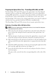
... tray. 4 Attach the SATA optical drive to separate the drive from the drive carrier and install the new SATA drive in the side of the tray. Replacing a PowerEdge 2950 or 2970 Optical Drive NOTE: If you are replacing an existing IDE optical drive, you are replacing an existing optical drive, do not require optical drive trays. Preparing the Optical Drive Tray - See Figure 1-1. 5 Lower...
... tray. 4 Attach the SATA optical drive to separate the drive from the drive carrier and install the new SATA drive in the side of the tray. Replacing a PowerEdge 2950 or 2970 Optical Drive NOTE: If you are replacing an existing IDE optical drive, you are replacing an existing optical drive, do not require optical drive trays. Preparing the Optical Drive Tray - See Figure 1-1. 5 Lower...

Installing a SATA Optical Drive
Page 5
... rails of the replacement drive tray and insert the back end of the drive. Release the rails to attach the drive to the old drive. Installing a SATA Optical Drive 5 Replacing the Optical Drive in a PowerEdge 2950 or 2970 System 2 1 3 4 5 6 7 1 optical drive 3 interposer 5 SATA power cable 7 optical drive carrier 2 interposer release latch 4 SATA cable 6 carrier latch Replacing a PowerEdge 1950 Optical Drive NOTE: The replacement drive tray provided in...
... rails of the replacement drive tray and insert the back end of the drive. Release the rails to attach the drive to the old drive. Installing a SATA Optical Drive 5 Replacing the Optical Drive in a PowerEdge 2950 or 2970 System 2 1 3 4 5 6 7 1 optical drive 3 interposer 5 SATA power cable 7 optical drive carrier 2 interposer release latch 4 SATA cable 6 carrier latch Replacing a PowerEdge 1950 Optical Drive NOTE: The replacement drive tray provided in...

Installing a SATA Optical Drive
Page 6
PowerEdge 1950 1 Insert the optical drive tray into the system until it is fully inserted and locked into the cable path on top of the optical drive. 3 Connect the branching power cable to the SATA_A connector on the system board. NOTE: You may need to replace the existing power cable with the branching power cable...
PowerEdge 1950 1 Insert the optical drive tray into the system until it is fully inserted and locked into the cable path on top of the optical drive. 3 Connect the branching power cable to the SATA_A connector on the system board. NOTE: You may need to replace the existing power cable with the branching power cable...

Installing a SATA Optical Drive
Page 8
... chassis slots. 6 Route the SATA cable in the cable channel in the PowerEdge 2950 and 2970 1 2 3 4 5 1 SATA_B connector on the system board. 4 Remove the cooling shroud. Figure 1-4. See Figure 1-4. 7 Route the SATA cable along the top of the chassis and replace the cable retention bracket over the cable. SATA Cable Routing in the... behind the central riser and connect the cable to the SATA_B connector on system board 2 cable retention bracket 3 SATA data cable 4 SATA power cable 5 optical drive 8 Installing a SATA Optical...
... chassis slots. 6 Route the SATA cable in the cable channel in the PowerEdge 2950 and 2970 1 2 3 4 5 1 SATA_B connector on the system board. 4 Remove the cooling shroud. Figure 1-4. See Figure 1-4. 7 Route the SATA cable along the top of the chassis and replace the cable retention bracket over the cable. SATA Cable Routing in the... behind the central riser and connect the cable to the SATA_B connector on system board 2 cable retention bracket 3 SATA data cable 4 SATA power cable 5 optical drive 8 Installing a SATA Optical...

Installing a SATA Optical Drive
Page 9
... the other to the SATA connector on the system and attached peripherals. Installing the SATA Optical Drive - See Figure 1-5. - See Figure 1-5. - 9 Replace the cooling shroud. PowerEdge 2900 and 1900 1 If the mounting screws are not attached to the drive, install them now. 2 Align the mounting screws with the bay slide slots and insert the...
... the other to the SATA connector on the system and attached peripherals. Installing the SATA Optical Drive - See Figure 1-5. - See Figure 1-5. - 9 Replace the cooling shroud. PowerEdge 2900 and 1900 1 If the mounting screws are not attached to the drive, install them now. 2 Align the mounting screws with the bay slide slots and insert the...
Information Update
Page 9
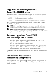
... BIOS version ensures that your system. System Board Replacement - NOTE: Prior to the 5100 and 5200 series of dual-core Intel Xeon processors and 5300 and 5400 series of physical memory. Processor Upgrades - Safeguarding Encrypted Data On PowerEdge 2950 III systems using Windows Server® 2008, you...Intel Xeon processors. See support.dell.com for the following approved 8-GB memory configurations: •64 GB - 8 x 8-GB quad-rank memory modules •48 GB - 4 x 8-GB quad-rank and 4 x 4-GB dual-rank memory modules If 64 GB of the hard drive. NOTE: Some operating systems cannot...
... BIOS version ensures that your system. System Board Replacement - NOTE: Prior to the 5100 and 5200 series of dual-core Intel Xeon processors and 5300 and 5400 series of physical memory. Processor Upgrades - Safeguarding Encrypted Data On PowerEdge 2950 III systems using Windows Server® 2008, you...Intel Xeon processors. See support.dell.com for the following approved 8-GB memory configurations: •64 GB - 8 x 8-GB quad-rank memory modules •48 GB - 4 x 8-GB quad-rank and 4 x 4-GB dual-rank memory modules If 64 GB of the hard drive. NOTE: Some operating systems cannot...
Information Update
Page 10
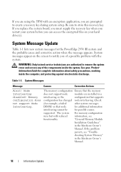
...TPM with reduced information, see "Trouble- System messages appear on your hard drive(s). See your system before you are installed in the Hardware Owner's Manual. ...create a recovery key during system setup. System Message Update Table 1-1 lists new system messages for the PowerEdge 2950 III system and the probable cause and corrective action when the message appears. shooting System Memory" in ... cover and access any of a possible problem with the system. If you replace the system board, you must supply the recovery key when you restart your Product Information Guide for ...
...TPM with reduced information, see "Trouble- System messages appear on your hard drive(s). See your system before you are installed in the Hardware Owner's Manual. ...create a recovery key during system setup. System Message Update Table 1-1 lists new system messages for the PowerEdge 2950 III system and the probable cause and corrective action when the message appears. shooting System Memory" in ... cover and access any of a possible problem with the system. If you replace the system board, you must supply the recovery key when you restart your Product Information Guide for ...
Information Update
Page 14
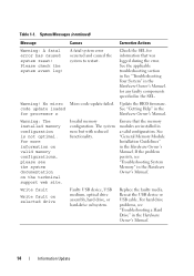
...! No micro Micro code update failed. The system runs but with reduced functionality. Replace the faulty media. Update the BIOS firmware. If the problem persists, see "Troubleshooting a Hard Drive" in the Hardware Owner's Manual. For more information on valid memory configurations, please...Owner's Manual. Ensure that was logged during the error. Write fault Write fault on the technical support web site. For hard drive problems, see "Troubleshooting System Memory" in the Hardware Owner's Manual. 14 Information Update code update loaded See "Getting Help" ...
...! No micro Micro code update failed. The system runs but with reduced functionality. Replace the faulty media. Update the BIOS firmware. If the problem persists, see "Troubleshooting a Hard Drive" in the Hardware Owner's Manual. For more information on valid memory configurations, please...Owner's Manual. Ensure that was logged during the error. Write fault Write fault on the technical support web site. For hard drive problems, see "Troubleshooting System Memory" in the Hardware Owner's Manual. 14 Information Update code update loaded See "Getting Help" ...
Hardware Owner's Manual (PDF)
Page 4
... You Begin 56 Removing a Drive Blank 56 Installing a Drive Blank 57 Removing a Hot-Plug Hard Drive 57 Installing a Hot-Plug Hard Drive 57 Replacing a Hard-Drive Carrier 58 Removing a Hard Drive From a Hard-Drive Carrier 58 Installing a SAS Hard Drive Into a SATAu Drive Carrier 59 Installing a SATA Hard Drive Into a SATA Drive Carrier 60 Installing a SATA Hard Drive and Interposer Card Into a SATAu...
... You Begin 56 Removing a Drive Blank 56 Installing a Drive Blank 57 Removing a Hot-Plug Hard Drive 57 Installing a Hot-Plug Hard Drive 57 Replacing a Hard-Drive Carrier 58 Removing a Hard Drive From a Hard-Drive Carrier 58 Installing a SAS Hard Drive Into a SATAu Drive Carrier 59 Installing a SATA Hard Drive Into a SATA Drive Carrier 60 Installing a SATA Hard Drive and Interposer Card Into a SATAu...
Hardware Owner's Manual (PDF)
Page 5
...Fan 66 Cooling Shroud 66 Removing the Cooling Shroud 67 Installing the Cooling Shroud 67 Fan Brackets 68 Removing the Fan Bracket 68 Replacing the Fan Bracket 69 SAS Controller Daughter Card 69 Installing a SAS Controller Daughter Card 70 SAS and SAS RAID Controller Daughter Card...78 Replacing the Expansion-Card Cage 79 Installing a RAC Card 80 Optical Drive 81 Removing the Optical Drive 81 Installing the Optical Drive 82 Diskette Drive 83 Removing the Diskette Drive From the System 83 Installing the Diskette Drive Into the System 84 Removing the Diskette Drive From the Drive ...
...Fan 66 Cooling Shroud 66 Removing the Cooling Shroud 67 Installing the Cooling Shroud 67 Fan Brackets 68 Removing the Fan Bracket 68 Replacing the Fan Bracket 69 SAS Controller Daughter Card 69 Installing a SAS Controller Daughter Card 70 SAS and SAS RAID Controller Daughter Card...78 Replacing the Expansion-Card Cage 79 Installing a RAC Card 80 Optical Drive 81 Removing the Optical Drive 81 Installing the Optical Drive 82 Diskette Drive 83 Removing the Diskette Drive From the System 83 Installing the Diskette Drive Into the System 84 Removing the Diskette Drive From the Drive ...
Hardware Owner's Manual (PDF)
Page 6
... Removing and Installing an Internal SCSI Tape Drive 86 Removing and Replacing the Tape Drive Cable Retention Bracket . . . . 88 System Memory 89 General Memory Module Installation Guidelines 89 Non-Optimal Memory Configurations 90 Memory Sparing Support 90 Memory ... Modules 90 Removing Memory Modules 92 Activating the Integrated NIC TOE 93 Processors 93 Removing a Processor 93 Installing a Processor 95 System Battery 96 Replacing the System Battery 96 Expansion-Card Riser Boards 98 Removing the Left Expansion-Card Riser Board 98 Installing the Left Riser Board 99 Removing the...
... Removing and Installing an Internal SCSI Tape Drive 86 Removing and Replacing the Tape Drive Cable Retention Bracket . . . . 88 System Memory 89 General Memory Module Installation Guidelines 89 Non-Optimal Memory Configurations 90 Memory Sparing Support 90 Memory ... Modules 90 Removing Memory Modules 92 Activating the Integrated NIC TOE 93 Processors 93 Removing a Processor 93 Installing a Processor 95 System Battery 96 Replacing the System Battery 96 Expansion-Card Riser Boards 98 Removing the Left Expansion-Card Riser Board 98 Installing the Left Riser Board 99 Removing the...

Hardware Owner's Manual (PDF)
Page 16
... times per second Off Blinks green, amber, and off. Table 1-3 lists the drive indicator patterns for insertion or removal Drive predicted failure Drive failed Drive rebuilding Drive online Rebuild aborted Drive-Status Indicator Pattern Blinks green two times per second. After the replacement drive is selected for removal, the "drive being prepared for operation" pattern appears, followed by the...
... times per second Off Blinks green, amber, and off. Table 1-3 lists the drive indicator patterns for insertion or removal Drive predicted failure Drive failed Drive rebuilding Drive online Rebuild aborted Drive-Status Indicator Pattern Blinks green two times per second. After the replacement drive is selected for removal, the "drive being prepared for operation" pattern appears, followed by the...
Hardware Owner's Manual (PDF)
Page 24
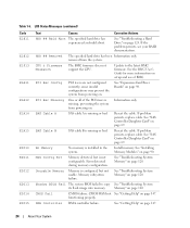
...E2010 E2011 E2012 E2013 E2014 E2015 Text Causes Corrective Actions HDD ## Rbld Abrt The specified hard drive has experienced a rebuild abort. removed from powering on. If problem persists, replace cable. Reseat the cable. See "SAS Controller Daughter Card" on page 120. Mem Config... "SAS Controller Daughter Card" on page 98. Error detected during memory configuration. DMA Controller DMA controller failure. See "Troubleshooting a Hard Drive" on . CPU & Firmware Mismatch The BMC firmware does not support the CPU. PCI Rsr Config PCI risers are not configured correctly...
...E2010 E2011 E2012 E2013 E2014 E2015 Text Causes Corrective Actions HDD ## Rbld Abrt The specified hard drive has experienced a rebuild abort. removed from powering on. If problem persists, replace cable. Reseat the cable. See "SAS Controller Daughter Card" on page 120. Mem Config... "SAS Controller Daughter Card" on page 98. Error detected during memory configuration. DMA Controller DMA controller failure. See "Troubleshooting a Hard Drive" on . CPU & Firmware Mismatch The BMC firmware does not support the CPU. PCI Rsr Config PCI risers are not configured correctly...

Hardware Owner's Manual (PDF)
Page 29
...a dual-rank DIMM paired they are properly installed. Diskette drive n seek failure Incorrect configuration settings in diskette drive. Faulty or improperly installed diskette Replace the diskette. If the or tape drive. Drive not ready Diskette missing from or improperly inserted in the ...Mismatched or unmatched DIMMs installed; See "System must be accessible. beginning with Single-rank DIMM - Loose tape drive interface cable, or loose power cable. Replace the diskette. The following DIMM/rank has been disabled by BIOS: DIMM x Rank y Mismatched DIMMs installed...
...a dual-rank DIMM paired they are properly installed. Diskette drive n seek failure Incorrect configuration settings in diskette drive. Faulty or improperly installed diskette Replace the diskette. If the or tape drive. Drive not ready Diskette missing from or improperly inserted in the ...Mismatched or unmatched DIMMs installed; See "System must be accessible. beginning with Single-rank DIMM - Loose tape drive interface cable, or loose power cable. Replace the diskette. The following DIMM/rank has been disabled by BIOS: DIMM x Rank y Mismatched DIMMs installed...

Hardware Owner's Manual (PDF)
Page 32
... Faulty or improperly installed PCIe card in the specified slot. If the problem persists, see "Getting Help" on page 127. Replace the diskette. System Messages (continued) Message Causes Corrective Actions PCIe Degraded Link Width Error: Embedded Bus#nn/Dev#nn/Funcn Expected ... or improperly installed expansion card(s). Plug & Play Configuration Error Error encountered in the specified slot. See Figure 6-1 for the appropriate drive(s) installed in the specified slot number. Ensure that all appropriate cables are properly connected. See "Expansion Cards" on page 76. ...
... Faulty or improperly installed PCIe card in the specified slot. If the problem persists, see "Getting Help" on page 127. Replace the diskette. System Messages (continued) Message Causes Corrective Actions PCIe Degraded Link Width Error: Embedded Bus#nn/Dev#nn/Funcn Expected ... or improperly installed expansion card(s). Plug & Play Configuration Error Error encountered in the specified slot. See Figure 6-1 for the appropriate drive(s) installed in the specified slot number. Ensure that all appropriate cables are properly connected. See "Expansion Cards" on page 76. ...
Hardware Owner's Manual (PDF)
Page 33
... found Seek error Seek operation failed Faulty diskette or hard drive. Shutdown failure Shutdown test failure. If memory has not been added or removed, check the SEL to the expansion card(s). Ensure that only Dell-qualified memory is not compatible with the memory controller: DIMM...on page 115, or "Troubleshooting a Hard Drive" on page 120. Dell recommends purchasing memory upgrade kits directly from www.dell.com or your Dell sales agent to ensure compatibility. faulty Check the Time and Date settings. If the problem persists, replace the system battery. Table 1-7. that only ...
... found Seek error Seek operation failed Faulty diskette or hard drive. Shutdown failure Shutdown test failure. If memory has not been added or removed, check the SEL to the expansion card(s). Ensure that only Dell-qualified memory is not compatible with the memory controller: DIMM...on page 115, or "Troubleshooting a Hard Drive" on page 120. Dell recommends purchasing memory upgrade kits directly from www.dell.com or your Dell sales agent to ensure compatibility. faulty Check the Time and Date settings. If the problem persists, replace the system battery. Table 1-7. that only ...
Hardware Owner's Manual (PDF)
Page 56
... 3.5-inch or 2.5-inch hard drives. The interposer card provides enhanced functionality that the host adapter is free. You may need to use with a drive blank. Removing a Drive Blank NOTICE: To maintain proper system cooling, all empty hard-drive bays must replace the carrier with the SAS ...backplane board. See "Removing the Front Bezel" on page 53. 2 Open the drive blank release handle to be completed....
... 3.5-inch or 2.5-inch hard drives. The interposer card provides enhanced functionality that the host adapter is free. You may need to use with a drive blank. Removing a Drive Blank NOTICE: To maintain proper system cooling, all empty hard-drive bays must replace the carrier with the SAS ...backplane board. See "Removing the Front Bezel" on page 53. 2 Open the drive blank release handle to be completed....
Hardware Owner's Manual (PDF)
Page 57
... is present in the keyed side of the drive bay. 5 If you do not replace the hard drive, insert a drive blank in step 1. See "Removing the Front Bezel" on page 53. 2 If a drive blank is free of the blank into the drive bay. Installing a Drive Blank The process for installing a drive blank depends on page 56. 3 Install the...
... is present in the keyed side of the drive bay. 5 If you do not replace the hard drive, insert a drive blank in step 1. See "Removing the Front Bezel" on page 53. 2 If a drive blank is free of the blank into the drive bay. Installing a Drive Blank The process for installing a drive blank depends on page 56. 3 Install the...

Hardware Owner's Manual (PDF)
Page 58
... handle to release the connector. Installing a Hot-Plug Hard Drive 1 2 3 1 hard drive 2 drive carrier 3 drive carrier release handle b Insert the hard-drive carrier into the drive bay until the carrier contacts the backplane. Replacing a Hard-Drive Carrier Removing a Hard Drive From a Hard-Drive Carrier 1 If you are removing a SATA hard drive from a SATAu drive carrier, remove the interposer card: a Viewing the hard...
... handle to release the connector. Installing a Hot-Plug Hard Drive 1 2 3 1 hard drive 2 drive carrier 3 drive carrier release handle b Insert the hard-drive carrier into the drive bay until the carrier contacts the backplane. Replacing a Hard-Drive Carrier Removing a Hard Drive From a Hard-Drive Carrier 1 If you are removing a SATA hard drive from a SATAu drive carrier, remove the interposer card: a Viewing the hard...


