

Installing a SATA Optical Drive
Page 3
... disconnect the system from the center fan bracket. a Disconnect the SAS cable from the SAS controller and pull the cable away from the electrical outlet. 2 Remove the bezel. Installing a SATA Optical Drive These instructions apply to Dell™ PowerEdge™ systems to remove the system... cover and access any of the system. WARNING: Only trained service technicians are authorized to which a SATA optical drive is being added, or in your Hardware Owner's Manual. 4 PowerEdge 1950 systems only: ...
... disconnect the system from the center fan bracket. a Disconnect the SAS cable from the SAS controller and pull the cable away from the electrical outlet. 2 Remove the bezel. Installing a SATA Optical Drive These instructions apply to Dell™ PowerEdge™ systems to remove the system... cover and access any of the system. WARNING: Only trained service technicians are authorized to which a SATA optical drive is being added, or in your Hardware Owner's Manual. 4 PowerEdge 1950 systems only: ...

Installing a SATA Optical Drive
Page 6
... chipset shroud. b Bend the cable toward the chipset shroud and insert the cable into position. 2 Connect the SATA cable (the end with a cable provided in a PowerEdge 1950 Drive Tray 2 3 1 4 5 1 optical drive 3 SATA power cable 5 optical drive carrier 2 SATA cable 4 carrier latch Installing the SATA Optical Drive - Figure 1-2. Installing a ...board. 6 Installing a SATA Optical Drive c Connect the cable to the power supply bays. a Route the cable through the power cable cutout in the fan bracket and follow the power cable routing to the SATA_A connector on the system board.
... chipset shroud. b Bend the cable toward the chipset shroud and insert the cable into position. 2 Connect the SATA cable (the end with a cable provided in a PowerEdge 1950 Drive Tray 2 3 1 4 5 1 optical drive 3 SATA power cable 5 optical drive carrier 2 SATA cable 4 carrier latch Installing the SATA Optical Drive - Figure 1-2. Installing a ...board. 6 Installing a SATA Optical Drive c Connect the cable to the power supply bays. a Route the cable through the power cable cutout in the fan bracket and follow the power cable routing to the SATA_A connector on the system board.

Installing a SATA Optical Drive
Page 7
...PowerEdge 2970 or 2950 1 Insert the optical drive tray into the system until it is fully inserted and locked into position. 2 Connect the SATA cable (the end with the branching power cable) to the back of the optical drive. 3 Connect the branching power cable to power and turn on system board 4 system fans... 6 optical drive 5 Reinstall the SAS controller daughter card and reconnect the SAS cable. Installing the SATA Optical Drive - Installing a SATA Optical Drive 7 SATA Cable Routing in the PowerEdge 1950 2 1 3 4 6 5 1 SATA data...
...PowerEdge 2970 or 2950 1 Insert the optical drive tray into the system until it is fully inserted and locked into position. 2 Connect the SATA cable (the end with the branching power cable) to the back of the optical drive. 3 Connect the branching power cable to power and turn on system board 4 system fans... 6 optical drive 5 Reinstall the SAS controller daughter card and reconnect the SAS cable. Installing the SATA Optical Drive - Installing a SATA Optical Drive 7 SATA Cable Routing in the PowerEdge 1950 2 1 3 4 6 5 1 SATA data...

Installing a SATA Optical Drive
Page 9
... back of the fan bracket and connect the cable to the power supply as follows: - See "Installing the Cooling Shroud" in the optical drive kit and connect one end to the optical drive and the other to the SATA connector on the system board. For a PowerEdge 2900 system, connect... to an available power supply cable. 5 Replace the center fan bracket. For a PowerEdge 2900, use the SATA_D connector. 9 Replace the cooling shroud. See "Replacing the Center...
... back of the fan bracket and connect the cable to the power supply as follows: - See "Installing the Cooling Shroud" in the optical drive kit and connect one end to the optical drive and the other to the SATA connector on the system board. For a PowerEdge 2900 system, connect... to an available power supply cable. 5 Replace the center fan bracket. For a PowerEdge 2900, use the SATA_D connector. 9 Replace the cooling shroud. See "Replacing the Center...
Information Update
Page 15
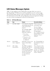
... SYSTEM NAME displays under the following conditions: • The system is powered on the PowerEdge 2950 III system and the probable cause for each message. The BMC is for critical failure events. Consequently, the BMC increases the CPU fan speed to events recorded in the Hardware Owner's Manual. Information Update 15 You can...
... SYSTEM NAME displays under the following conditions: • The system is powered on the PowerEdge 2950 III system and the probable cause for each message. The BMC is for critical failure events. Consequently, the BMC increases the CPU fan speed to events recorded in the Hardware Owner's Manual. Information Update 15 You can...

Getting Started Guide
Page 5
... 1 redundant configuration. • Four hot-pluggable system cooling fans. To take advantage of this feature, you must order the processor upgrade kits from Dell contains the correct version of the processor, heat sink, and fan as well as additional processors. System Features The major hardware ...configurations) provides support for symmetric multiprocessing (SMP), which provides memory sparing or memory mirroring. The upgrade kit from Dell. Getting Started With Your System 3 NOTE: If you decide to a maximum of 32 GB by dividing processor operations between independent processors...
... 1 redundant configuration. • Four hot-pluggable system cooling fans. To take advantage of this feature, you must order the processor upgrade kits from Dell contains the correct version of the processor, heat sink, and fan as well as additional processors. System Features The major hardware ...configurations) provides support for symmetric multiprocessing (SMP), which provides memory sparing or memory mirroring. The upgrade kit from Dell. Getting Started With Your System 3 NOTE: If you decide to a maximum of 32 GB by dividing processor operations between independent processors...
Getting Started Guide
Page 6
... With Your System For more information about booting from an external device attached to eight 2.5-inch SAS or six 3.5-inch SATA hard drives. See support.dell.com for the latest support information about specific features, see "Technical Specifications" on separate PCI-X buses (capable of throttling back to support legacy PCI add... has one full-length PCIe x8 lane slot and one full-length PCIe x4 lane slot. This video subsystem contains 16 MB of the system fans as well as critical system voltages and temperatures.
... With Your System For more information about booting from an external device attached to eight 2.5-inch SAS or six 3.5-inch SATA hard drives. See support.dell.com for the latest support information about specific features, see "Technical Specifications" on separate PCI-X buses (capable of throttling back to support legacy PCI add... has one full-length PCIe x8 lane slot and one full-length PCIe x4 lane slot. This video subsystem contains 16 MB of the system fans as well as critical system voltages and temperatures.
Hardware Owner's Manual (PDF)
Page 5
... Cooling Shroud 66 Removing the Cooling Shroud 67 Installing the Cooling Shroud 67 Fan Brackets 68 Removing the Fan Bracket 68 Replacing the Fan Bracket 69 SAS Controller Daughter Card 69 Installing a SAS Controller Daughter Card 70 SAS and SAS RAID Controller Daughter Card Cabling Guidelines . . . . . 72 Removing a SAS ...
... Cooling Shroud 66 Removing the Cooling Shroud 67 Installing the Cooling Shroud 67 Fan Brackets 68 Removing the Fan Bracket 68 Replacing the Fan Bracket 69 SAS Controller Daughter Card 69 Installing a SAS Controller Daughter Card 70 SAS and SAS RAID Controller Daughter Card Cabling Guidelines . . . . . 72 Removing a SAS ...
Hardware Owner's Manual (PDF)
Page 7
... a NIC 116 Troubleshooting a Wet System 116 Troubleshooting a Damaged System 117 Troubleshooting the System Battery 118 Troubleshooting Power Supplies 118 Troubleshooting System Cooling Problems 119 Troubleshooting a Fan 119 Troubleshooting System Memory 120 Troubleshooting a Diskette Drive 121 Troubleshooting an Optical Drive 123 Troubleshooting an External SCSI Tape Drive 123 Troubleshooting a Hard Drive 124...
... a NIC 116 Troubleshooting a Wet System 116 Troubleshooting a Damaged System 117 Troubleshooting the System Battery 118 Troubleshooting Power Supplies 118 Troubleshooting System Cooling Problems 119 Troubleshooting a Fan 119 Troubleshooting System Memory 120 Troubleshooting a Diskette Drive 121 Troubleshooting an Optical Drive 123 Troubleshooting an External SCSI Tape Drive 123 Troubleshooting a Hard Drive 124...
Hardware Owner's Manual (PDF)
Page 20
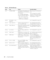
... Support Temp Ambient E1116 Temp Memory E12nn xx PwrGd E1210 CMOS Batt E1211 ROMB Batt E1229 CPU # VCORE E1310 RPM Fan ## E1313 Fan Redundancy Causes Corrective Actions A 62-character string that can change the system ID The SYSTEM NAME displays and name in ...CMOS battery is missing, or the See "Troubleshooting the System voltage is for redundant. See "RAID Battery" on page 119. Another fan failure additional scrolling messages. page 74, and "Troubleshooting System Cooling Problems" on thermal issues. "Troubleshooting System Cooling heating. Memory has ...
... Support Temp Ambient E1116 Temp Memory E12nn xx PwrGd E1210 CMOS Batt E1211 ROMB Batt E1229 CPU # VCORE E1310 RPM Fan ## E1313 Fan Redundancy Causes Corrective Actions A 62-character string that can change the system ID The SYSTEM NAME displays and name in ...CMOS battery is missing, or the See "Troubleshooting the System voltage is for redundant. See "RAID Battery" on page 119. Another fan failure additional scrolling messages. page 74, and "Troubleshooting System Cooling Problems" on thermal issues. "Troubleshooting System Cooling heating. Memory has ...
Hardware Owner's Manual (PDF)
Page 27
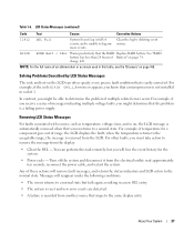
... occur. For example, if you receive a series of Battery" on page 169. Removing LCD Status Messages For faults associated with sensors, such as temperature, voltage, fans, and so on the LCD can perform this task remotely, but fails again, resulting in this table, see the "Glossary" on page 74. You can...
... occur. For example, if you receive a series of Battery" on page 169. Removing LCD Status Messages For faults associated with sensors, such as temperature, voltage, fans, and so on the LCD can perform this task remotely, but fails again, resulting in this table, see the "Glossary" on page 74. You can...
Hardware Owner's Manual (PDF)
Page 35
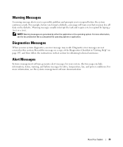
... system. For more information, see the systems management software documentation. About Your System 35 Alert Messages Systems management software generates alert messages for drive, temperature, fan, and power conditions. For example, before the system continues a task. Diagnostic error messages are generated by typing y (yes) or n (no). Warning messages usually interrupt the...
... system. For more information, see the systems management software documentation. About Your System 35 Alert Messages Systems management software generates alert messages for drive, temperature, fan, and power conditions. For example, before the system continues a task. Diagnostic error messages are generated by typing y (yes) or n (no). Warning messages usually interrupt the...

Hardware Owner's Manual (PDF)
Page 51
Installing System Components This section describes how to install the following system components: • Hard drives • Power supplies • System fans • Cooling shroud • Fan brackets • SAS controller daughter card • RAID battery • Expansion cards • Expansion card cage • RAC card • Optical, diskette, and tape drives &#...
Installing System Components This section describes how to install the following system components: • Hard drives • Power supplies • System fans • Cooling shroud • Fan brackets • SAS controller daughter card • RAID battery • Expansion cards • Expansion card cage • RAC card • Optical, diskette, and tape drives &#...
Hardware Owner's Manual (PDF)
Page 52
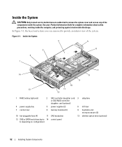
... 3 sideplane or SAS RAID controller daughter card (optional) 4 power supply bay 5 power supplies (2) 6 left riser 7 central riser 8 memory modules (8) 9 heatsinks and microprocessors (2) 10 hot-pluggable fans (4) 11 SAS backplane 12 slimline optical drive (optional) 13 SAS or SATA hard drives (up to remove the system cover and access any of the...
... 3 sideplane or SAS RAID controller daughter card (optional) 4 power supply bay 5 power supplies (2) 6 left riser 7 central riser 8 memory modules (8) 9 heatsinks and microprocessors (2) 10 hot-pluggable fans (4) 11 SAS backplane 12 slimline optical drive (optional) 13 SAS or SATA hard drives (up to remove the system cover and access any of the...
Hardware Owner's Manual (PDF)
Page 54
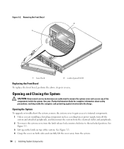
... the computer, and protecting against electrostatic discharge. Opening and Closing the System CAUTION: Only trained service technicians are installing a hot-plug component such as a cooling fan or power supply, turn the latch release lock counter-clockwise to remove the system cover and access any of the system. See your Product Information...
... the computer, and protecting against electrostatic discharge. Opening and Closing the System CAUTION: Only trained service technicians are installing a hot-plug component such as a cooling fan or power supply, turn the latch release lock counter-clockwise to remove the system cover and access any of the system. See your Product Information...
Hardware Owner's Manual (PDF)
Page 65
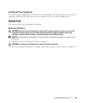
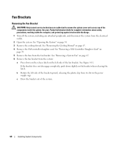
... about safety precautions, working inside the system. CAUTION: Use caution when handling the fan until the fan blades stop spinning. 2 Raise the fan handle and pull the fan straight up from the fan cage to remove the system cover and access any of the blank into the power... supply bay and secure with the Phillips screw. See Figure 3-9. Installing System Components 65 System Fans The system includes four hot-pluggable cooling fans. Removing a System Fan CAUTION: Only trained service technicians are hot-pluggable. Rotate the blank into the slot in the power supply...
... about safety precautions, working inside the system. CAUTION: Use caution when handling the fan until the fan blades stop spinning. 2 Raise the fan handle and pull the fan straight up from the fan cage to remove the system cover and access any of the blank into the power... supply bay and secure with the Phillips screw. See Figure 3-9. Installing System Components 65 System Fans The system includes four hot-pluggable cooling fans. Removing a System Fan CAUTION: Only trained service technicians are hot-pluggable. Rotate the blank into the slot in the power supply...
Hardware Owner's Manual (PDF)
Page 66
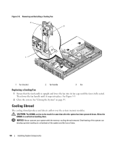
.... CAUTION: The DIMMs are hot to cool before handling them. See "Closing the System" on page 55. Then lower the fan handle until it snaps into its fan cage until the fan is fully seated. Figure 3-9. Allow the DIMMs to the touch for some time after the system has been powered down. Removing...
.... CAUTION: The DIMMs are hot to cool before handling them. See "Closing the System" on page 55. Then lower the fan handle until it snaps into its fan cage until the fan is fully seated. Figure 3-9. Allow the DIMMs to the touch for some time after the system has been powered down. Removing...
Hardware Owner's Manual (PDF)
Page 67
Figure 3-10. See Figure 3-10. 2 Slowly lower the shroud straight down into the system until the fan connector engages and the latches snap into place. Installing System Components 67 See Figure 3-10. 2 Rotate the shroud upward and toward the front ... the latch by pulling it towards the outside wall of the shroud. Removing and Installing the Cooling Shroud 2 3 1 4 5 1 shroud pivots (2) 4 shroud hinges (2) 2 cooling shroud 5 fan bracket 3 release latch Installing the Cooling Shroud 1 Align the hinges on the shroud pivots located on its hinges, and then lift the shroud out of...
Figure 3-10. See Figure 3-10. 2 Slowly lower the shroud straight down into the system until the fan connector engages and the latches snap into place. Installing System Components 67 See Figure 3-10. 2 Rotate the shroud upward and toward the front ... the latch by pulling it towards the outside wall of the shroud. Removing and Installing the Cooling Shroud 2 3 1 4 5 1 shroud pivots (2) 4 shroud hinges (2) 2 cooling shroud 5 fan bracket 3 release latch Installing the Cooling Shroud 1 Align the hinges on the shroud pivots located on its hinges, and then lift the shroud out of...
Hardware Owner's Manual (PDF)
Page 68
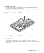
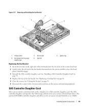
...the SAS controller daughter card. If the bracket does not disengage completely, push down on the release latch on page 74 5 Remove the fans from the fan bracket. c Draw the bracket out of the system. 68 Installing System Components See Figure 3-11. See "Removing a SAS Controller Daughter Card... upward, releasing the plastic clip from its slot in the power supply cage. b Rotate the left side of the fan bracket. Fan Brackets Removing the Fan Bracket CAUTION: Only trained service technicians are authorized to remove the system cover and access any of the components inside the...
...the SAS controller daughter card. If the bracket does not disengage completely, push down on the release latch on page 74 5 Remove the fans from the fan bracket. c Draw the bracket out of the system. 68 Installing System Components See Figure 3-11. See "Removing a SAS Controller Daughter Card... upward, releasing the plastic clip from its slot in the power supply cage. b Rotate the left side of the fan bracket. Fan Brackets Removing the Fan Bracket CAUTION: Only trained service technicians are authorized to remove the system cover and access any of the components inside the...
Hardware Owner's Manual (PDF)
Page 69
...the System" on page 55. 6 Reconnect the system to set up any internal hard drives in the fan bracket. See "Installing a SAS Controller Daughter Card" on page 70. 4 Replace the fans in a RAID Installing System Components 69 SAS Controller Daughter Card Your system includes a dedicated slot on ... the system until the release latch and plastic clip fully engage. 3 Reinstall the SAS controller daughter card. See "Replacing a Cooling Fan" on the system and attached peripherals. The optional SAS RAID controller daughter card allows you to the electrical outlet and turn on page...
...the System" on page 55. 6 Reconnect the system to set up any internal hard drives in the fan bracket. See "Installing a SAS Controller Daughter Card" on page 70. 4 Replace the fans in a RAID Installing System Components 69 SAS Controller Daughter Card Your system includes a dedicated slot on ... the system until the release latch and plastic clip fully engage. 3 Reinstall the SAS controller daughter card. See "Replacing a Cooling Fan" on the system and attached peripherals. The optional SAS RAID controller daughter card allows you to the electrical outlet and turn on page...


