

Installing a SATA Optical Drive
Page 6
... connector on top of the chipset shroud. See Figure 1-3. Installing a SATA Optical Drive in the optical drive kit. 4 Route the SATA cable to the power supply connector. Figure 1-2. PowerEdge 1950 1 Insert the optical drive tray into the system until it is fully inserted and locked into the cable path on the system board.
... connector on top of the chipset shroud. See Figure 1-3. Installing a SATA Optical Drive in the optical drive kit. 4 Route the SATA cable to the power supply connector. Figure 1-2. PowerEdge 1950 1 Insert the optical drive tray into the system until it is fully inserted and locked into the cable path on the system board.

Installing a SATA Optical Drive
Page 7
... Owner's Manual. 6 Close the system. PowerEdge 2970 or 2950 1 Insert the optical drive tray into the system until it is fully inserted and locked into position. 2 Connect the SATA cable (the end with the branching power cable) to the back of the optical ... See "Closing the System" in your Hardware Owner's Manual. 7 Reconnect the system to the power supply connector. SATA Cable Routing in the PowerEdge 1950 2 1 3 4 6 5 1 SATA data cable 3 chipset shroud 5 SATA power cable 2 SATA_A connector on the system and attached peripherals. Installing a SATA Optical Drive 7 Figure...
... Owner's Manual. 6 Close the system. PowerEdge 2970 or 2950 1 Insert the optical drive tray into the system until it is fully inserted and locked into position. 2 Connect the SATA cable (the end with the branching power cable) to the back of the optical ... See "Closing the System" in your Hardware Owner's Manual. 7 Reconnect the system to the power supply connector. SATA Cable Routing in the PowerEdge 1950 2 1 3 4 6 5 1 SATA data cable 3 chipset shroud 5 SATA power cable 2 SATA_A connector on the system and attached peripherals. Installing a SATA Optical Drive 7 Figure...

Installing a SATA Optical Drive
Page 9
...Installing the Cooling Shroud" in your Hardware Owner's Manual. 11 Reconnect the system to power and turn on the system and attached peripherals. For a PowerEdge 2900 system, connect to the power supply as follows: - For a PowerEdge 1900, use the SATA_B connector. - See "Closing the System" in your Hardware ...and connect the cable to an available power supply cable. 5 Replace the center fan bracket. See "Replacing the Center Fan Bracket" in your Hardware Owner's Manual. 10 Close the system. Installing the SATA Optical Drive - For a PowerEdge 1900 system, connect to the SATA ...
...Installing the Cooling Shroud" in your Hardware Owner's Manual. 11 Reconnect the system to power and turn on the system and attached peripherals. For a PowerEdge 2900 system, connect to the power supply as follows: - For a PowerEdge 1900, use the SATA_B connector. - See "Closing the System" in your Hardware ...and connect the cable to an available power supply cable. 5 Replace the center fan bracket. See "Replacing the Center Fan Bracket" in your Hardware Owner's Manual. 10 Close the system. Installing the SATA Optical Drive - For a PowerEdge 1900 system, connect to the SATA ...
Information Update
Page 3
Safeguarding Encrypted Data 9 System Message Update 10 LCD Status Messages Update 15 Contents 3 Contents Non-Optimal Memory Configurations 5 PowerEdge 2950 III - PowerEdge 2950 III Systems 9 Processor Upgrades - Power 2950 II and PowerEdge 2950 III Systems 9 System Board Replacement - New System Features 5 New Performance Features 5 New High-Efficiency Power Supply and Power Monitoring Features 5 New I/O and Storage Features 6 New Security Features 6 Optional Internal USB Memory Key 6 Installing the Optional Internal USB Memory Key 7 Support for 8-GB Memory Modules -
Safeguarding Encrypted Data 9 System Message Update 10 LCD Status Messages Update 15 Contents 3 Contents Non-Optimal Memory Configurations 5 PowerEdge 2950 III - PowerEdge 2950 III Systems 9 Processor Upgrades - Power 2950 II and PowerEdge 2950 III Systems 9 System Board Replacement - New System Features 5 New Performance Features 5 New High-Efficiency Power Supply and Power Monitoring Features 5 New I/O and Storage Features 6 New Security Features 6 Optional Internal USB Memory Key 6 Installing the Optional Internal USB Memory Key 7 Support for 8-GB Memory Modules -

Information Update
Page 5
... the slowest speed in the system. PowerEdge 2950 III - The system clocks down the performance to continue or F2 for the channel. New High-Efficiency Power Supply and Power Monitoring Features • Higher system efficiency on power conversion across workloads. • Baseboard Management Control (BMC) power monitoring monitors current, voltage, and power utilization in the DIMM set for...
... the slowest speed in the system. PowerEdge 2950 III - The system clocks down the performance to continue or F2 for the channel. New High-Efficiency Power Supply and Power Monitoring Features • Higher system efficiency on power conversion across workloads. • Baseboard Management Control (BMC) power monitoring monitors current, voltage, and power utilization in the DIMM set for...

Getting Started Guide
Page 5
...Dell. Either feature is available on the system board. System Features The major hardware and software features of your system by installing a second processor, you must use an operating system that signals the appropriate systems management software if the top cover is opened. • Up to two hot-pluggable, 750-W power supplies...slim-line IDE CD, DVD, or combination CD-RW/DVD drive. NOTE: If you must order the processor upgrade kits from Dell contains the correct version of the processor, heat sink, and fan as well as additional processors. SMP greatly improves overall system ...
...Dell. Either feature is available on the system board. System Features The major hardware and software features of your system by installing a second processor, you must use an operating system that signals the appropriate systems management software if the top cover is opened. • Up to two hot-pluggable, 750-W power supplies...slim-line IDE CD, DVD, or combination CD-RW/DVD drive. NOTE: If you must order the processor upgrade kits from Dell contains the correct version of the processor, heat sink, and fan as well as additional processors. SMP greatly improves overall system ...

Getting Started Guide
Page 9
... the monitor (optional) and system power, and connect the system's power cable(s) to system's integrated video connector. Getting Started With Your System 7 Plug the other end of your system has an expansion card with a video output ... connector. The connectors on the back of the cable into each connector. Instead, connect the monitor cable to plug into a grounded electrical outlet or a separate power source such as an uninterrupted power supply (UPS) or a power distribution unit (PDU). Be sure to tighten the screws (if any) on the expansion card.
... the monitor (optional) and system power, and connect the system's power cable(s) to system's integrated video connector. Getting Started With Your System 7 Plug the other end of your system has an expansion card with a video output ... connector. The connectors on the back of the cable into each connector. Instead, connect the monitor cable to plug into a grounded electrical outlet or a separate power source such as an uninterrupted power supply (UPS) or a power distribution unit (PDU). Be sure to tighten the screws (if any) on the expansion card.

Getting Started Guide
Page 10
...the System Turn on the system and the monitor. Repeat the procedure for the second power supply. Bend the system power cable into a grounded electrical outlet or a separate power source such as shown in the illustration and attach to the bracket's cable clasp. Adjust... image is satisfactory. 8 Getting Started With Your System Installing the Power Cord Retention Bracket Attach the power cord retention bracket on the right bend of the power cables into a loop as an uninterrupted power supply (UPS) or a power distribution unit (PDU). The power indicators should light.
...the System Turn on the system and the monitor. Repeat the procedure for the second power supply. Bend the system power cable into a grounded electrical outlet or a separate power source such as shown in the illustration and attach to the bracket's cable clasp. Adjust... image is satisfactory. 8 Getting Started With Your System Installing the Power Cord Retention Bracket Attach the power cord retention bracket on the right bend of the power cables into a loop as an uninterrupted power supply (UPS) or a power distribution unit (PDU). The power indicators should light.

Getting Started Guide
Page 13
...11 Drives (continued) Optical drive Tape drive Flash drive Connectors Back NIC Serial USB Video Front Video USB Video Video type Video memory Power AC power supply (per power supply for integrated 1-GB NICs) 9-pin, DTE, 16550-compatible Two 4-pin, USB 2.0-compliant 15-pin VGA 15-pin VGA Two .../hr maximum Under typical line conditions and over the entire system ambient operating range, the inrush current may reach 55 A per power supply) Wattage Voltage Heat dissipation Maximum inrush current Batteries System battery RAID battery (optional) one optional internal half height tape backup device...
...11 Drives (continued) Optical drive Tape drive Flash drive Connectors Back NIC Serial USB Video Front Video USB Video Video type Video memory Power AC power supply (per power supply for integrated 1-GB NICs) 9-pin, DTE, 16550-compatible Two 4-pin, USB 2.0-compliant 15-pin VGA 15-pin VGA Two .../hr maximum Under typical line conditions and over the entire system ambient operating range, the inrush current may reach 55 A per power supply) Wattage Voltage Heat dissipation Maximum inrush current Batteries System battery RAID battery (optional) one optional internal half height tape backup device...
Hardware Owner's Manual (PDF)
Page 4
... Drive Carrier 59 Installing a SATA Hard Drive Into a SATA Drive Carrier 60 Installing a SATA Hard Drive and Interposer Card Into a SATAu Hard-Drive Carrier 61 Power Supplies 62 Removing a Power Supply 63 Replacing a Power Supply 64 Removing the Power Supply Blank 64 Installing the Power Supply Blank 65 4 Contents
... Drive Carrier 59 Installing a SATA Hard Drive Into a SATA Drive Carrier 60 Installing a SATA Hard Drive and Interposer Card Into a SATAu Hard-Drive Carrier 61 Power Supplies 62 Removing a Power Supply 63 Replacing a Power Supply 64 Removing the Power Supply Blank 64 Installing the Power Supply Blank 65 4 Contents
Hardware Owner's Manual (PDF)
Page 7
... Troubleshooting a Serial I/O Device 115 Troubleshooting a USB Device 115 Troubleshooting a NIC 116 Troubleshooting a Wet System 116 Troubleshooting a Damaged System 117 Troubleshooting the System Battery 118 Troubleshooting Power Supplies 118 Troubleshooting System Cooling Problems 119 Troubleshooting a Fan 119 Troubleshooting System Memory 120 Troubleshooting a Diskette Drive 121 Troubleshooting an Optical Drive 123 Troubleshooting an External...
... Troubleshooting a Serial I/O Device 115 Troubleshooting a USB Device 115 Troubleshooting a NIC 116 Troubleshooting a Wet System 116 Troubleshooting a Damaged System 117 Troubleshooting the System Battery 118 Troubleshooting Power Supplies 118 Troubleshooting System Cooling Problems 119 Troubleshooting a Fan 119 Troubleshooting System Memory 120 Troubleshooting a Diskette Drive 121 Troubleshooting an Optical Drive 123 Troubleshooting an External...

Hardware Owner's Manual (PDF)
Page 13
...-Panel LED Indicators, Buttons, and Connectors Item Indicator, Button, or Connector Icon 1 Power-on indicator, power button 2 NMI button 3 System identification button Description The power-on indicator lights when the system power is turned off immediately after the power button is pushed again. Front-Panel Features and Indicators 1 2 3 4 5 6... This button can be pressed using the power button and the system is running an ACPI-compliant operating system, the power is turned off . The power button controls the DC power supply output to do so by qualified support ...
...-Panel LED Indicators, Buttons, and Connectors Item Indicator, Button, or Connector Icon 1 Power-on indicator, power button 2 NMI button 3 System identification button Description The power-on indicator lights when the system power is turned off immediately after the power button is pushed again. Front-Panel Features and Indicators 1 2 3 4 5 6... This button can be pressed using the power button and the system is running an ACPI-compliant operating system, the power is turned off . The power button controls the DC power supply output to do so by qualified support ...

Hardware Owner's Manual (PDF)
Page 17
Back-Panel Features and Indicators 1 2 3 4 13 12 11 10 9 87 6 5 1 center PCI riser (slot 1) 4 power supplies (2) 7 system status indicator connector 10 USB connectors (2) 13 remote access controller (optional) 2 left PCI riser (slot 2) 5 system identification button 8 NIC2 connector 3 left PCI riser (slot 3) 6 ...
Back-Panel Features and Indicators 1 2 3 4 13 12 11 10 9 87 6 5 1 center PCI riser (slot 1) 4 power supplies (2) 7 system status indicator connector 10 USB connectors (2) 13 remote access controller (optional) 2 left PCI riser (slot 2) 5 system identification button 8 NIC2 connector 3 left PCI riser (slot 3) 6 ...
Hardware Owner's Manual (PDF)
Page 18
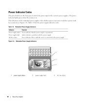
... the redundant power supplies show whether power is connected to the system's power supplies. Power supply fault Amber indicates a problem with the power supply. AC line status Green indicates that the power supply is on. Figure 1-4. Redundant Power Supply Indicators Indicator Function Power supply status Green indicates that a valid AC source is present or whether a power fault has occurred (see Figure 1-4). Redundant Power Supply Indicators 1 2 3 1 power supply status 2 power supply fault 3 AC...
... the redundant power supplies show whether power is connected to the system's power supplies. Power supply fault Amber indicates a problem with the power supply. AC line status Green indicates that the power supply is on. Figure 1-4. Redundant Power Supply Indicators Indicator Function Power supply status Green indicates that a valid AC source is present or whether a power fault has occurred (see Figure 1-4). Redundant Power Supply Indicators 1 2 3 1 power supply status 2 power supply fault 3 AC...

Hardware Owner's Manual (PDF)
Page 22
.... 22 About Your System PS # Status No power is available from the specified power supply; Check the AC power source for specified power supply is unavailable, or out of See "Troubleshooting Power acceptable range; specified power supply is improperly installed or faulty. specified power Supplies" on page 118. Check the AC power source for specified power supply is unavailable, or out of acceptable range...
.... 22 About Your System PS # Status No power is available from the specified power supply; Check the AC power source for specified power supply is unavailable, or out of See "Troubleshooting Power acceptable range; specified power supply is improperly installed or faulty. specified power Supplies" on page 118. Check the AC power source for specified power supply is unavailable, or out of acceptable range...
Hardware Owner's Manual (PDF)
Page 27
...you will reappear under the following conditions: • The sensor returns to the same display entry. wait approximately ten seconds, reconnect the power cable, and restart the system. For example, if the code E1418 CPU_1_Presence appears, you might determine that a microprocessor is recorded from...SEL - In contrast, you know that the problem is easily corrected. W1228 ROMB Batt < 24hr Warns predictively that is a failing power supply. About Your System 27 when the temperature returns to determine the problem if multiple related errors occur. Table 1-6. Clear the log by...
...you will reappear under the following conditions: • The sensor returns to the same display entry. wait approximately ten seconds, reconnect the power cable, and restart the system. For example, if the code E1418 CPU_1_Presence appears, you might determine that a microprocessor is recorded from...SEL - In contrast, you know that the problem is easily corrected. W1228 ROMB Batt < 24hr Warns predictively that is a failing power supply. About Your System 27 when the temperature returns to determine the problem if multiple related errors occur. Table 1-6. Clear the log by...

Hardware Owner's Manual (PDF)
Page 51
Installing System Components This section describes how to install the following system components: • Hard drives • Power supplies • System fans • Cooling shroud • Fan brackets • SAS controller daughter card • RAID battery • Expansion cards • Expansion card cage • ...
Installing System Components This section describes how to install the following system components: • Hard drives • Power supplies • System fans • Cooling shroud • Fan brackets • SAS controller daughter card • RAID battery • Expansion cards • Expansion card cage • ...
Hardware Owner's Manual (PDF)
Page 52
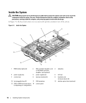
Figure 3-1. Inside the System 4 5 3 6 2 1 14 13 9 10 11 12 7 8 1 RAID battery (optional) 2 SAS controller daughter card 3 sideplane or SAS RAID controller daughter card (optional) 4 power supply bay 5 power supplies (2) 6 left riser 7 central riser 8 memory modules (8) 9 heatsinks and microprocessors (2) 10 hot-pluggable fans (4) 11 SAS backplane 12 slimline optical drive (optional) 13 SAS or SATA ...
Figure 3-1. Inside the System 4 5 3 6 2 1 14 13 9 10 11 12 7 8 1 RAID battery (optional) 2 SAS controller daughter card 3 sideplane or SAS RAID controller daughter card (optional) 4 power supply bay 5 power supplies (2) 6 left riser 7 central riser 8 memory modules (8) 9 heatsinks and microprocessors (2) 10 hot-pluggable fans (4) 11 SAS backplane 12 slimline optical drive (optional) 13 SAS or SATA ...
Hardware Owner's Manual (PDF)
Page 54
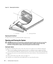
... authorized to the unlocked position. Opening and Closing the System CAUTION: Only trained service technicians are installing a hot-plug component such as a cooling fan or power supply, turn the latch release lock counter-clockwise to remove the system cover and access any of the system. See Figure 3-3. 4 Grasp the cover on top...
... authorized to the unlocked position. Opening and Closing the System CAUTION: Only trained service technicians are installing a hot-plug component such as a cooling fan or power supply, turn the latch release lock counter-clockwise to remove the system cover and access any of the system. See Figure 3-3. 4 Grasp the cover on top...

Hardware Owner's Manual (PDF)
Page 62
If two power supplies are installed, the second power supply serves as a redundant, hot-plug power source. NOTICE: To ensure proper system cooling, the power supply blank must be installed on page 65. 62 Installing System Components Installing a SATA Hard Drive and ...only) Power Supplies Your system supports one power supply is installed, it must be installed in a non-redundant configuration. Figure 3-7. If only one or two power supplies rated at an output of 750 W. See "Installing the Power Supply Blank" on the unoccupied power supply bay in the left power supply bay (1)....
If two power supplies are installed, the second power supply serves as a redundant, hot-plug power source. NOTICE: To ensure proper system cooling, the power supply blank must be installed on page 65. 62 Installing System Components Installing a SATA Hard Drive and ...only) Power Supplies Your system supports one power supply is installed, it must be installed in a non-redundant configuration. Figure 3-7. If only one or two power supplies rated at an output of 750 W. See "Installing the Power Supply Blank" on the unoccupied power supply bay in the left power supply bay (1)....


