
Installing a SATA Optical Drive
Page 1
Dell™ PowerEdge™ 19x0 and 29x0 Systems Installing a SATA Optical Drive
Dell™ PowerEdge™ 19x0 and 29x0 Systems Installing a SATA Optical Drive

Installing a SATA Optical Drive
Page 3
... bay. 7 For systems with the system. See "Opening the System" in which an existing PATA or IDE optical drive is being replaced by a SATA optical drive. Installing a SATA Optical Drive These instructions apply to Dell™ PowerEdge™ systems to remove the system cover and access any of the system. Before you begin this procedure...
... bay. 7 For systems with the system. See "Opening the System" in which an existing PATA or IDE optical drive is being replaced by a SATA optical drive. Installing a SATA Optical Drive These instructions apply to Dell™ PowerEdge™ systems to remove the system cover and access any of the system. Before you begin this procedure...
Installing a SATA Optical Drive
Page 4
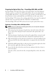
... used for the SATA optical drive. PowerEdge 2970, 2950, and 1950 For PowerEdge 2970 and 2950 systems, the optical drive tray that shipped with the SATA drive installation kit. Replacing a PowerEdge 2950 or 2970 Optical Drive NOTE: If you are replacing an existing IDE optical drive, you are replacing an existing optical drive, do not require optical drive trays. The pins on the...
... used for the SATA optical drive. PowerEdge 2970, 2950, and 1950 For PowerEdge 2970 and 2950 systems, the optical drive tray that shipped with the SATA drive installation kit. Replacing a PowerEdge 2950 or 2970 Optical Drive NOTE: If you are replacing an existing IDE optical drive, you are replacing an existing optical drive, do not require optical drive trays. The pins on the...

Installing a SATA Optical Drive
Page 5
...Drive in a PowerEdge 2950 or 2970 System 2 1 3 4 5 6 7 1 optical drive 3 interposer 5 SATA power cable 7 optical drive carrier 2 interposer release latch 4 SATA cable 6 carrier latch Replacing a PowerEdge 1950 Optical Drive NOTE: The replacement drive tray provided in the installation kit must be used with the holes in the side of the SATA optical drive... into the tray until the pins on the carrier align with PowerEdge 1950 systems. If you are replacing an existing optical drive, do not reuse the interposer board attached to the ...
...Drive in a PowerEdge 2950 or 2970 System 2 1 3 4 5 6 7 1 optical drive 3 interposer 5 SATA power cable 7 optical drive carrier 2 interposer release latch 4 SATA cable 6 carrier latch Replacing a PowerEdge 1950 Optical Drive NOTE: The replacement drive tray provided in the installation kit must be used with the holes in the side of the SATA optical drive... into the tray until the pins on the carrier align with PowerEdge 1950 systems. If you are replacing an existing optical drive, do not reuse the interposer board attached to the ...

Installing a SATA Optical Drive
Page 6
... supply connector. a Route the cable through the power cable cutout in a PowerEdge 1950 Drive Tray 2 3 1 4 5 1 optical drive 3 SATA power cable 5 optical drive carrier 2 SATA cable 4 carrier latch Installing the SATA Optical Drive - NOTE: You may need to replace the existing power cable with the branching... power cable) to the SATA_A connector on the system board. 6 Installing a SATA Optical Drive PowerEdge 1950 1 Insert the optical drive tray into the system until it is fully inserted and locked into the cable path on the system board. See Figure...
... supply connector. a Route the cable through the power cable cutout in a PowerEdge 1950 Drive Tray 2 3 1 4 5 1 optical drive 3 SATA power cable 5 optical drive carrier 2 SATA cable 4 carrier latch Installing the SATA Optical Drive - NOTE: You may need to replace the existing power cable with the branching... power cable) to the SATA_A connector on the system board. 6 Installing a SATA Optical Drive PowerEdge 1950 1 Insert the optical drive tray into the system until it is fully inserted and locked into the cable path on the system board. See Figure...

Installing a SATA Optical Drive
Page 7
Installing the SATA Optical Drive - See "Closing the System" in your Hardware Owner's Manual. 6 Close the system. PowerEdge 2970 or 2950 1 Insert the optical drive tray into the system until it is fully inserted and locked into position. 2 Connect the SATA cable (the end with the ...branching power cable) to the back of the optical drive. 3 Connect the branching power cable to...
Installing the SATA Optical Drive - See "Closing the System" in your Hardware Owner's Manual. 6 Close the system. PowerEdge 2970 or 2950 1 Insert the optical drive tray into the system until it is fully inserted and locked into position. 2 Connect the SATA cable (the end with the ...branching power cable) to the back of the optical drive. 3 Connect the branching power cable to...

Installing a SATA Optical Drive
Page 8
... bracket toward the front of the system until the bracket detaches from the chassis slots. 6 Route the SATA cable in the cable channel in the PowerEdge 2950 and 2970 1 2 3 4 5 1 SATA_B connector on the system board. See Figure 1-4. 7 Route the SATA cable along the top of the chassis and replace the cable retention... behind the central riser and connect the cable to the SATA_B connector on system board 2 cable retention bracket 3 SATA data cable 4 SATA power cable 5 optical drive 8 Installing a SATA Optical...
... bracket toward the front of the system until the bracket detaches from the chassis slots. 6 Route the SATA cable in the cable channel in the PowerEdge 2950 and 2970 1 2 3 4 5 1 SATA_B connector on the system board. See Figure 1-4. 7 Route the SATA cable along the top of the chassis and replace the cable retention... behind the central riser and connect the cable to the SATA_B connector on system board 2 cable retention bracket 3 SATA data cable 4 SATA power cable 5 optical drive 8 Installing a SATA Optical...

Installing a SATA Optical Drive
Page 9
..."Replacing the Center Fan Bracket" in the optical drive kit and connect one end to the optical drive and the other to the SATA connector on the system and attached peripherals. Installing a SATA Optical Drive 9 For a PowerEdge 2900 system, connect to an available power supply cable.... 5 Replace the center fan bracket. See Figure 1-5. - For a PowerEdge 2900, use the SATA_D connector. 9 Replace the cooling shroud. See ...
..."Replacing the Center Fan Bracket" in the optical drive kit and connect one end to the optical drive and the other to the SATA connector on the system and attached peripherals. Installing a SATA Optical Drive 9 For a PowerEdge 2900 system, connect to an available power supply cable.... 5 Replace the center fan bracket. See Figure 1-5. - For a PowerEdge 2900, use the SATA_D connector. 9 Replace the cooling shroud. See ...

Installing a SATA Optical Drive
Page 10
See "Closing the System" in a PowerEdge 2900 or 1900 3 2 4 5 1 1 optical drive 3 SATA data cable 5 SATA power connector on SAS backplane (PowerEdge 2900 only) 2 SATA power cable 4 SATA connector on the system and attached peripherals. 10 Installing a SATA Optical Drive Figure 1-5. SATA Cable Routing in your Hardware Owner's Manual. 10 Reconnect the system to power and turn on system board 8 Reconnect the cables to the SAS controller daughter card. 9 Close the system.
See "Closing the System" in a PowerEdge 2900 or 1900 3 2 4 5 1 1 optical drive 3 SATA data cable 5 SATA power connector on SAS backplane (PowerEdge 2900 only) 2 SATA power cable 4 SATA connector on the system and attached peripherals. 10 Installing a SATA Optical Drive Figure 1-5. SATA Cable Routing in your Hardware Owner's Manual. 10 Reconnect the system to power and turn on system board 8 Reconnect the cables to the SAS controller daughter card. 9 Close the system.

Information Update
Page 6
... data rates, and iSCSI remote boot. • Support for 10-Gb Ethernet cards. • One internal USB 2.0-compliant connector supporting an optional bootable USB flash drive or USB memory key. • Support for iSCSI boot. To use with components inside the system, the USB key must be used as a boot device...
... data rates, and iSCSI remote boot. • Support for 10-Gb Ethernet cards. • One internal USB 2.0-compliant connector supporting an optional bootable USB flash drive or USB memory key. • Support for iSCSI boot. To use with components inside the system, the USB key must be used as a boot device...
Information Update
Page 9
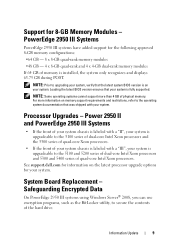
For more than 4 GB of the hard drive. See support.dell.com for information on the latest processor upgrade options for the following approved 8-GB memory configurations: •64 GB - 8 x 8-GB quad-rank memory modules •.... • If the front of quad-core Intel Xeon processors. System Board Replacement - Loading the latest BIOS version ensures that your system. Processor Upgrades - PowerEdge 2950 III Systems PowerEdge 2950 III systems have added support for your system is upgradeable to the 5100 and 5200 series of dual-core Intel Xeon processors and 5300...
For more than 4 GB of the hard drive. See support.dell.com for information on the latest processor upgrade options for the following approved 8-GB memory configurations: •64 GB - 8 x 8-GB quad-rank memory modules •.... • If the front of quad-core Intel Xeon processors. System Board Replacement - Loading the latest BIOS version ensures that your system. Processor Upgrades - PowerEdge 2950 III Systems PowerEdge 2950 III systems have added support for your system is upgradeable to the 5100 and 5200 series of dual-core Intel Xeon processors and 5300...
Information Update
Page 10
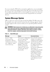
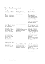
... and access any of a possible problem with reduced information, see "Trouble- The memory configuration Ensure that node for additional information interleaving cannot be for the PowerEdge 2950 III system and the probable cause and corrective action when the message appears. System Message Update Table 1-1 lists new system messages for possible causes. The... of the components inside the computer, and protecting against electrostatic discharge. shooting System Memory" in the Hardware Owner's Manual. 10 Information Update See your hard drive(s).
... and access any of a possible problem with reduced information, see "Trouble- The memory configuration Ensure that node for additional information interleaving cannot be for the PowerEdge 2950 III system and the probable cause and corrective action when the message appears. System Message Update Table 1-1 lists new system messages for possible causes. The... of the components inside the computer, and protecting against electrostatic discharge. shooting System Memory" in the Hardware Owner's Manual. 10 Information Update See your hard drive(s).
Information Update
Page 11
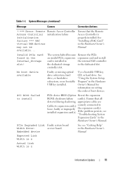
... Embedded device See see "Troubleshooting System Expansion Cards" in the Hardware Owner's Manual. Use a bootable USB key, CD, or hard drive. System Messages (continued) Message Causes Corrective Actions !!*** Error: Remote Access Controller initialization failure *** RAC virtual USB devices may not be ... Owner's Manual for information on setting the order of boot devices. No boot device available Faulty or missing optical drive subsystem, hard drive, or hard-drive subsystem, or no bootable USB key installed. If the problem persists, see "Getting Help" in the Hardware Owner...
... Embedded device See see "Troubleshooting System Expansion Cards" in the Hardware Owner's Manual. Use a bootable USB key, CD, or hard drive. System Messages (continued) Message Causes Corrective Actions !!*** Error: Remote Access Controller initialization failure *** RAC virtual USB devices may not be ... Owner's Manual for information on setting the order of boot devices. No boot device available Faulty or missing optical drive subsystem, hard drive, or hard-drive subsystem, or no bootable USB key installed. If the problem persists, see "Getting Help" in the Hardware Owner...
Information Update
Page 14
... and caused the system to restart. Update the BIOS firmware. If the problem persists, see the system documentation on selected drive Faulty USB device, USB medium, optical drive assembly, hard drive, or hard-drive subsystem. Warning! See "General Memory Module Installation Guidelines" in the Hardware Owner's Manual. Check the SEL for processor n Hardware Owner...
... and caused the system to restart. Update the BIOS firmware. If the problem persists, see the system documentation on selected drive Faulty USB device, USB medium, optical drive assembly, hard drive, or hard-drive subsystem. Warning! See "General Memory Module Installation Guidelines" in the Hardware Owner's Manual. Check the SEL for processor n Hardware Owner...
Information Update
Page 24
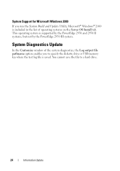
You cannot save the file to specify the diskette drive or USB memory key where the test log file is saved. System Diagnostics Update In the Customize window of operating systems on the Server OS ... diagnostics, the Log output file pathname option enables you run the System Build and Update Utility, Microsoft® Windows® 2000 is supported by the PowerEdge 2950 and 2950 II systems, but not by the PowerEdge 2950 III system. System Support for Microsoft Windows 2000 If you to a hard drive. 24 Information Update
You cannot save the file to specify the diskette drive or USB memory key where the test log file is saved. System Diagnostics Update In the Customize window of operating systems on the Server OS ... diagnostics, the Log output file pathname option enables you run the System Build and Update Utility, Microsoft® Windows® 2000 is supported by the PowerEdge 2950 and 2950 II systems, but not by the PowerEdge 2950 III system. System Support for Microsoft Windows 2000 If you to a hard drive. 24 Information Update

Information Update
Page 36
... information on valid memory configurations, please see the system documentation on the technical support web site. 降低。 Write fault Write fault on selected drive USB 设备、 USB USB 设备或 USB 36 信息更新 表 1-1 信息 原因 纠正措施 Warning...
... information on valid memory configurations, please see the system documentation on the technical support web site. 降低。 Write fault Write fault on selected drive USB 设备、 USB USB 设备或 USB 36 信息更新 表 1-1 信息 原因 纠正措施 Warning...

Information Update
Page 120
表 1-1 原因 対応処置 Warning! For more information on valid memory configurations, please see the system documentation on selected drive USB USB USB USB 120 Write fault Write fault on the technical support web site. No micro code update loaded for processor n BIOS ださい。 Warning: The installed memory configuration is not optimal.
表 1-1 原因 対応処置 Warning! For more information on valid memory configurations, please see the system documentation on selected drive USB USB USB USB 120 Write fault Write fault on the technical support web site. No micro code update loaded for processor n BIOS ださい。 Warning: The installed memory configuration is not optimal.
Information Update
Page 146
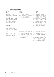
표 1-1 메시지 Warning: The installed memory configuration is not optimal. USB 장치 , USB USB USB 146 Write fault Write fault on the technical support web site. For more information on valid memory configurations, please see the system documentation on selected drive 원인 시오 .
표 1-1 메시지 Warning: The installed memory configuration is not optimal. USB 장치 , USB USB USB 146 Write fault Write fault on the technical support web site. For more information on valid memory configurations, please see the system documentation on selected drive 원인 시오 .

Getting Started Guide
Page 5
... the 3.5-inch x4 and 2.5-inch x8 backplane configurations) provides support for up to six 3.5-inch, internal hot-pluggable Serial Attached SCSI (SAS) or SATA hard drives without optional media bay, or up to a maximum of 32 GB by installing combinations of 256-MB, 512-MB, 1-GB, 2-GB, or 4-GB memory...processors. System Features The major hardware and software features of your system by installing a second processor, you must order the processor upgrade kits from Dell contains the correct version of the processor, heat sink, and fan as well as additional processors. The upgrade kit from...
... the 3.5-inch x4 and 2.5-inch x8 backplane configurations) provides support for up to six 3.5-inch, internal hot-pluggable Serial Attached SCSI (SAS) or SATA hard drives without optional media bay, or up to a maximum of 32 GB by installing combinations of 256-MB, 512-MB, 1-GB, 2-GB, or 4-GB memory...processors. System Features The major hardware and software features of your system by installing a second processor, you must order the processor upgrade kits from Dell contains the correct version of the processor, heat sink, and fan as well as additional processors. The upgrade kit from...
Getting Started Guide
Page 6
... of DDR SDRAM video memory (nonupgradable). See support.dell.com for the latest support information about specific features, see "Technical Specifications" on the back) capable of supporting a diskette drive, a CD-ROM drive, a keyboard, a mouse, or a USB flash drive. • Optional remote access controller (RAC) for.... • System ID button on separate PCI-X buses (capable of throttling back to eight 2.5-inch SAS or six 3.5-inch SATA hard drives. A left riser card options: - This video subsystem contains 16 MB of cache memory and a RAID battery. The systems management circuitry...
... of DDR SDRAM video memory (nonupgradable). See support.dell.com for the latest support information about specific features, see "Technical Specifications" on the back) capable of supporting a diskette drive, a CD-ROM drive, a keyboard, a mouse, or a USB flash drive. • Optional remote access controller (RAC) for.... • System ID button on separate PCI-X buses (capable of throttling back to eight 2.5-inch SAS or six 3.5-inch SATA hard drives. A left riser card options: - This video subsystem contains 16 MB of cache memory and a RAID battery. The systems management circuitry...


