
User Manual
Page 5
Contents Safety Instructions 5 SAFETY: Rack Mounting of Systems 5 Rack Installation Instructions 5 Rack Specifications 6 Before You Begin 6 Installation Tasks 7 Recommended Tools and Supplies 7 Removing and Replacing the Rack Doors 8 Removing and Replacing the Side Panels . . . . . 12 Reversing the Front Door (Optional 16 Securing the Rack Leveling Feet 23 Installing the Rack Stabilizer Feet 24 Adjusting the Rack Posts (Optional 27 Routing Cables 28 Coupling Two Racks 32 Contents 3
Contents Safety Instructions 5 SAFETY: Rack Mounting of Systems 5 Rack Installation Instructions 5 Rack Specifications 6 Before You Begin 6 Installation Tasks 7 Recommended Tools and Supplies 7 Removing and Replacing the Rack Doors 8 Removing and Replacing the Side Panels . . . . . 12 Reversing the Front Door (Optional 16 Securing the Rack Leveling Feet 23 Installing the Rack Stabilizer Feet 24 Adjusting the Rack Posts (Optional 27 Routing Cables 28 Coupling Two Racks 32 Contents 3
User Manual
Page 7
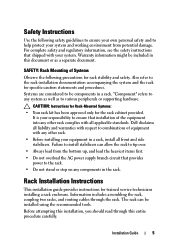
... the rack for rack stability and safety. CAUTION: Instructions for Rack-Mounted Systems: • Your rack kit has been approved only for trained service technicians installing a rack enclosure. Failure to install stabilizers can be included in a rack. Also refer to be components in this entire procedure carefully. Rack Installation Instructions This installation guide provides instructions for the rack cabinet provided. Information includes assembling the rack, coupling two racks, and routing cables through this document...
... the rack for rack stability and safety. CAUTION: Instructions for Rack-Mounted Systems: • Your rack kit has been approved only for trained service technicians installing a rack enclosure. Failure to install stabilizers can be included in a rack. Also refer to be components in this entire procedure carefully. Rack Installation Instructions This installation guide provides instructions for the rack cabinet provided. Information includes assembling the rack, coupling two racks, and routing cables through this document...

User Manual
Page 9
...; 12-mm wrench Installation Guide 7 The weight of the rack on racks joined to tip over and cause injury. Installation Tasks Installing a rack cabinet involves the following tasks: 1 Removing and replacing the rack doors 2 Removing and replacing the side panels 3 Reversing the front door and badge (optional) 4 Securing the leveling feet 5 Installing the stabilizer feet 6 Adjusting the rack posts (optional) 7 Routing cables through the rack 8 Coupling two racks (optional) Recommended...
...; 12-mm wrench Installation Guide 7 The weight of the rack on racks joined to tip over and cause injury. Installation Tasks Installing a rack cabinet involves the following tasks: 1 Removing and replacing the rack doors 2 Removing and replacing the side panels 3 Reversing the front door and badge (optional) 4 Securing the leveling feet 5 Installing the stabilizer feet 6 Adjusting the rack posts (optional) 7 Routing cables through the rack 8 Coupling two racks (optional) Recommended...

User Manual
Page 14
... lock into place. 12 Installation Guide Removing and Replacing the Side Panels CAUTION: For stand-alone racks, reinstalling the side panels is not mandatory for installing systems in a rack, having the sides open makes it easier to install slide assemblies and support rails and to ensure proper cooling within the rack. NOTE: You must remove the lower side panels in the rack to reverse the direction that...
... lock into place. 12 Installation Guide Removing and Replacing the Side Panels CAUTION: For stand-alone racks, reinstalling the side panels is not mandatory for installing systems in a rack, having the sides open makes it easier to install slide assemblies and support rails and to ensure proper cooling within the rack. NOTE: You must remove the lower side panels in the rack to reverse the direction that...

User Manual
Page 33
... bars used to stabilize the back doors can be removed, making it easier to route cables through the top and bottom of the rack. 1 Open the back doors. 2 Pull and hold the plungers on each side of the bar, and pull the bar up and away from the rack (see Figure 1-18). 3 After routing your cables, replace the...
... bars used to stabilize the back doors can be removed, making it easier to route cables through the top and bottom of the rack. 1 Open the back doors. 2 Pull and hold the plungers on each side of the bar, and pull the bar up and away from the rack (see Figure 1-18). 3 After routing your cables, replace the...

User Manual
Page 34
... matter on one of the rack cabinets, never attempt to be in Figure 1-19. Rack Coupling Kit 2 1 1 gasket strip 2 coupling bracket (4) 3 Remove the doors and side panels from both racks from being scratched. 32 Installation Guide See "Removing the Front Door" on page 9, "Opening and Removing the Back Doors" on page 10, and "Removing and Replacing the Side Panels" on page 12. 4 Cut and...
... matter on one of the rack cabinets, never attempt to be in Figure 1-19. Rack Coupling Kit 2 1 1 gasket strip 2 coupling bracket (4) 3 Remove the doors and side panels from both racks from being scratched. 32 Installation Guide See "Removing the Front Door" on page 9, "Opening and Removing the Back Doors" on page 10, and "Removing and Replacing the Side Panels" on page 12. 4 Cut and...
Dell PowerEdge 2420 Rack Installation Guide
Page 7
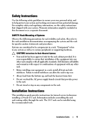
.... Safety Instructions Use the following precautions for specific caution statements and procedures. Systems are considered to be installed using the recommended tools. Dell disclaims all liability and warranties with all front and side stabilizers. Information includes assembling the rack and routing cables through the rack. CAUTION: Instructions for Rack-Mounted Systems: • Your rack kit has been approved only for trained service technicians installing a 24-unit (U) rack. Installation Guide 5
.... Safety Instructions Use the following precautions for specific caution statements and procedures. Systems are considered to be installed using the recommended tools. Dell disclaims all liability and warranties with all front and side stabilizers. Information includes assembling the rack and routing cables through the rack. CAUTION: Instructions for Rack-Mounted Systems: • Your rack kit has been approved only for trained service technicians installing a 24-unit (U) rack. Installation Guide 5

Dell PowerEdge 2420 Rack Installation Guide
Page 28
... bars used to stabilize the back doors can be removed, making it easier to route cables through the top and bottom of the rack. 1 Open the back doors. 2 Pull and hold the plungers on each side of the bar, and pull the bar up and away from the rack (see Figure 1-16). 3 After routing your cables, replace the...
... bars used to stabilize the back doors can be removed, making it easier to route cables through the top and bottom of the rack. 1 Open the back doors. 2 Pull and hold the plungers on each side of the bar, and pull the bar up and away from the rack (see Figure 1-16). 3 After routing your cables, replace the...
User Manual
Page 7
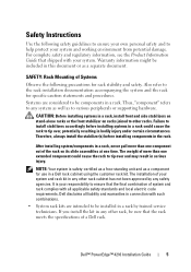
... time. Therefore, always install the stabilizer(s) before installing systems in a rack could cause the rack to other rack, be installed in serious injury. After installing system/components in a rack, never pull more than one extended component could cause the rack to various peripherals or supporting hardware. Dell disclaims all applicable safety standards and local electric code requirements. Dell™ PowerEdge™ 4210 Installation Guide 5 SAFETY: Rack Mounting of Systems Observe...
... time. Therefore, always install the stabilizer(s) before installing systems in a rack could cause the rack to other rack, be installed in serious injury. After installing system/components in a rack, never pull more than one extended component could cause the rack to various peripherals or supporting hardware. Dell disclaims all applicable safety standards and local electric code requirements. Dell™ PowerEdge™ 4210 Installation Guide 5 SAFETY: Rack Mounting of Systems Observe...
User Manual
Page 9
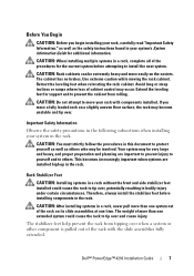
... of the rack with components installed. CAUTION: After installing systems in this document to tip over , potentially resulting in your rack, carefully read "Important Safety Information," as well as others . Dell™ PowerEdge™ 4210 Installation Guide 7 Before You Begin CAUTION: Before you move a fully loaded rack on the casters. Use extreme caution while moving the rack cabinet. CAUTION: When installing multiple systems...
... of the rack with components installed. CAUTION: After installing systems in this document to tip over , potentially resulting in your rack, carefully read "Important Safety Information," as well as others . Dell™ PowerEdge™ 4210 Installation Guide 7 Before You Begin CAUTION: Before you move a fully loaded rack on the casters. Use extreme caution while moving the rack cabinet. CAUTION: When installing multiple systems...
Cabling PowerEdge R815
Page 4
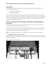
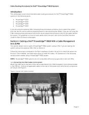
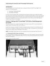
... Dell™ PowerEdge™ R815 systems in the rail kit to install the server into the rack. For guidelines on how to route cables within the rack, refer to install the cables. Section 1: Cabling a Dell™ PowerEdge™ R815 With a Cable Management Arm (CMA) This section details how to the rear of the cables behind the system. Connect all connections are not compatible with Cables Installed Page 2 Follow the instructions contained in the Rack Installation Guide...
... Dell™ PowerEdge™ R815 systems in the rail kit to install the server into the rack. For guidelines on how to route cables within the rack, refer to install the cables. Section 1: Cabling a Dell™ PowerEdge™ R815 With a Cable Management Arm (CMA) This section details how to the rear of the cables behind the system. Connect all connections are not compatible with Cables Installed Page 2 Follow the instructions contained in the Rack Installation Guide...
Cabling PowerEdge R810
Page 4
... the Rack Installation Guide in the rail kit to the rear of the system and verify that all applicable cables to install the server into the rack. Connect all connections are secure. If you are cabling the system without powering down or disconnecting the cables. NOTE: PowerEdge™ R810 systems are not compatible with Cables Installed Page 2 See Figure 1. Once installed, use these instructions to extend the system from the rack for service...
... the Rack Installation Guide in the rail kit to the rear of the system and verify that all applicable cables to install the server into the rack. Connect all connections are secure. If you are cabling the system without powering down or disconnecting the cables. NOTE: PowerEdge™ R810 systems are not compatible with Cables Installed Page 2 See Figure 1. Once installed, use these instructions to extend the system from the rack for service...
Cabling PowerEdge R715
Page 4
... server into the rack. If you are not using the CMA, following these procedures will allow you to extend the system from the rack for service without the optional CMA, refer to cable a PowerEdge™ R715 system using a PowerEdge™ R715 system. Follow the instructions contained in the Rack Installation Guide in the rail kit to install the cables. NOTE: PowerEdge™ R715 systems are cabling the system without powering...
... server into the rack. If you are not using the CMA, following these procedures will allow you to extend the system from the rack for service without the optional CMA, refer to cable a PowerEdge™ R715 system using a PowerEdge™ R715 system. Follow the instructions contained in the Rack Installation Guide in the rail kit to install the cables. NOTE: PowerEdge™ R715 systems are cabling the system without powering...

Cabling PowerEdge R710
Page 3
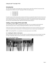
...Figure 2: Routing Power Cables Through the Strain Reliefs 3 2.3 Routing the Cables Through the CMA...3 Figure 3: Routing the Cables Through the CMA 4 Figure 4: Completed Left Side Mounted CMA Installation 5 Figure 5: Completed Right Side Mounted CMA Installation 5 Cabling a PowerEdge R710 Without a CMA ...5 3.1 Routing the Cables ...5 Figure 6: Cable Routing Without a CMA...6 Replacing a Power Supply on a PowerEdge R710 with CMA 6 Figure 7: Replacing Outer Power Supply ...7 Cabling a PowerEdge R710 Installed in Static Rails 7 Figure 8: Cabling a System Installed in Static Rails 7 Page 1
...Figure 2: Routing Power Cables Through the Strain Reliefs 3 2.3 Routing the Cables Through the CMA...3 Figure 3: Routing the Cables Through the CMA 4 Figure 4: Completed Left Side Mounted CMA Installation 5 Figure 5: Completed Right Side Mounted CMA Installation 5 Cabling a PowerEdge R710 Without a CMA ...5 3.1 Routing the Cables ...5 Figure 6: Cable Routing Without a CMA...6 Replacing a Power Supply on a PowerEdge R710 with CMA 6 Figure 7: Replacing Outer Power Supply ...7 Cabling a PowerEdge R710 Installed in Static Rails 7 Figure 8: Cabling a System Installed in Static Rails 7 Page 1
Cabling PowerEdge R710
Page 4
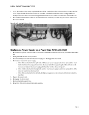
... how to route cables within the rack, refer to cable a PowerEdge R710 using a PowerEdge R710. Follow the instructions contained in the Rack Installation Guide found in the CMA kit. Plug in the following these procedures will ensure secure attachment and strain relief of the rails as described in the CMA Installation Instructions provided in the rail kit to install the server into the rack and to the rear of the...
... how to route cables within the rack, refer to cable a PowerEdge R710 using a PowerEdge R710. Follow the instructions contained in the Rack Installation Guide found in the CMA kit. Plug in the following these procedures will ensure secure attachment and strain relief of the rails as described in the CMA Installation Instructions provided in the rail kit to install the server into the rack and to the rear of the...
Cabling PowerEdge R710
Page 8
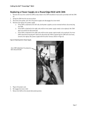
... the power supply and disengage the strain relief. 4. Remove and replace the power supply a. Plug in Figure 7. Replace the CMA support tray. 8. Disconnect the power cord from under the CMA as described in the Rack Installation Guide. Swing the CMA into the service position. 3. If the CMA is attached to either the left CMA bracket. 3. Figure 6: Cable Routing Without a CMA Replacing a Power Supply on a PowerEdge R710 with the rail kit...
... the power supply and disengage the strain relief. 4. Remove and replace the power supply a. Plug in Figure 7. Replace the CMA support tray. 8. Disconnect the power cord from under the CMA as described in the Rack Installation Guide. Swing the CMA into the service position. 3. If the CMA is attached to either the left CMA bracket. 3. Figure 6: Cable Routing Without a CMA Replacing a Power Supply on a PowerEdge R710 with the rail kit...

Cabling PowerEdge R610
Page 3
... Dongle to the CMA Basket 4 Figure 5: Completed Left Side Mounted CMA Installation 5 Figure 6: Completed Right Side Mounted CMA Installation 5 Cabling a PowerEdge R610 without a CMA ...6 3.1 Routing the Cables ...6 Figure 7: Cable Routing Without a CMA 6 3.1 Removing the CMA Brackets for Shallow Racks 6 Figure 8: Removing the CMA Brackets for Shallow Racks 6 Replacing a Power Supply on a PowerEdge R610 with CMA 7 Figure 9: Replacing Outer Power Supply 7 Cabling a PowerEdge R610 Installed in Static Rails 8 Figure 10: Cabling a System Installed in Static Rails 8 Page 1
... Dongle to the CMA Basket 4 Figure 5: Completed Left Side Mounted CMA Installation 5 Figure 6: Completed Right Side Mounted CMA Installation 5 Cabling a PowerEdge R610 without a CMA ...6 3.1 Routing the Cables ...6 Figure 7: Cable Routing Without a CMA 6 3.1 Removing the CMA Brackets for Shallow Racks 6 Figure 8: Removing the CMA Brackets for Shallow Racks 6 Replacing a Power Supply on a PowerEdge R610 with CMA 7 Figure 9: Replacing Outer Power Supply 7 Cabling a PowerEdge R610 Installed in Static Rails 8 Figure 10: Cabling a System Installed in Static Rails 8 Page 1
Cabling PowerEdge R610
Page 9
...c. While supporting the CMA with one hand, remove and replace the power supply with CMA 1. Remove and replace the power supply a. If the CMA is attached to be removed without disconnecting the CMA. Plug in the power cord. 6. b. Figure 9: Replacing Outer Power Supply Inner CMA ...Cabling the Dell™ PowerEdge™ R610 Replacing a Power Supply on a PowerEdge R610 with the other hand as described in the CMA Installation Instructions provided with the CMA kit. 2. Remove the tray from the power supply and disengage the strain relief. 4. Swing the CMA into the service...
...c. While supporting the CMA with one hand, remove and replace the power supply with CMA 1. Remove and replace the power supply a. If the CMA is attached to be removed without disconnecting the CMA. Plug in the power cord. 6. b. Figure 9: Replacing Outer Power Supply Inner CMA ...Cabling the Dell™ PowerEdge™ R610 Replacing a Power Supply on a PowerEdge R610 with the other hand as described in the CMA Installation Instructions provided with the CMA kit. 2. Remove the tray from the power supply and disengage the strain relief. 4. Swing the CMA into the service...
Best Practices Guide for Rack Enclosures
Page 4
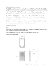
.... Dell PowerEdge servers fit into these racks as a guide to accommodate server mounting needs at both small office environments and in two sizes, 24U (2420) and 42U (4220). While not all deployment scenarios can be used . The 2420 Rack Enclosure is solidly built and delivered with Dell quality service, support, and reliability. Dell 2420 and 4220 Rack Enclosures are UL certified and adhere to address critical power, cooling, and cabling...
.... Dell PowerEdge servers fit into these racks as a guide to accommodate server mounting needs at both small office environments and in two sizes, 24U (2420) and 42U (4220). While not all deployment scenarios can be used . The 2420 Rack Enclosure is solidly built and delivered with Dell quality service, support, and reliability. Dell 2420 and 4220 Rack Enclosures are UL certified and adhere to address critical power, cooling, and cabling...
Best Practices Guide for Rack Enclosures
Page 8
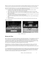
...rack frame. • Using a 17mm wrench or socket set, remove the bolts attaching the front L-brackets to the pallet. Dell Inc. | Data Center Infrastructure 8 The 2420 and 4220 Rack Enclosures are secured to their shipping pallet with L-brackets in the front and Z-brackets in place. • Close the front door. • With the assistance of at the rear...the rack with assistance to help guide and position the rack as it into Place Prior to moving a rack, verify that the rear castor wheels are 360-degree swiveling castor wheels, while the front wheels are in a readily accessible ...
...rack frame. • Using a 17mm wrench or socket set, remove the bolts attaching the front L-brackets to the pallet. Dell Inc. | Data Center Infrastructure 8 The 2420 and 4220 Rack Enclosures are secured to their shipping pallet with L-brackets in the front and Z-brackets in place. • Close the front door. • With the assistance of at the rear...the rack with assistance to help guide and position the rack as it into Place Prior to moving a rack, verify that the rear castor wheels are 360-degree swiveling castor wheels, while the front wheels are in a readily accessible ...

