PowerEdge 2400 - Dell
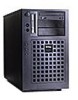
PowerEdge 2400
View Results Below
Free Dell PowerEdge 2400 manuals!
Problems with Dell PowerEdge 2400?
Ask a Question
Free Dell PowerEdge 2400 manuals!
Problems with Dell PowerEdge 2400?
Ask a Question
Related Manual Pages

Related Videos

Dell PowerEdge 2400 Server
Duration: 3:08
Total Views: 1,283
Duration: 3:08
Total Views: 1,283
Dell PowerEdge 2400
Duration: :41
Total Views: 9
Duration: :41
Total Views: 9
Dell Poweredge 2400 Server Destruction
Duration: 2:05
Total Views: 29
Duration: 2:05
Total Views: 29
Similar Questions

Flashing Green Light On Raid Controller - Dell Poweredge T105
What is the meaning of the flashing green light on the add-in raid controller of the Dell PowerEdge ...
What is the meaning of the flashing green light on the add-in raid controller of the Dell PowerEdge ...
(Posted by wwilly 9 years ago)

How To Upgrade The Firmware On A Dell Poweredge 2400 Server
(Posted by pldtnisc 9 years ago)


Hard Drive
I need to replace my Dell Hard Drives. I have (2) Dell 2400 Computers which I had for years. I have ...
I need to replace my Dell Hard Drives. I have (2) Dell 2400 Computers which I had for years. I have ...
(Posted by jstep45 12 years ago)