
Service Manual
Page 3
Contents Chapter 1 System Overview 1-1 System Features 1-1 System Memory 1-5 Advanced Expansion Subsystem 1-6 Integrated Server Management 1-6 Video Controller 1-6 Integrated SCSI Controller 1-6 SCSI Hard-Disk Drives 1-7 SCSI Configuration Guidelines 1-7 SCSI ID Numbers 1-7 Device Termination 1-8 System Unit 1-10 System Power Supply 1-10 Pin Assignments for the DC Power Connectors 1-10 DC Power Distribution 1-12 System Board Layout 1-14 System Board Jumpers 1-15 Interrupt Assignments 1-17 DMA Channel Assignments 1-18 Technical Specifications 1-19 v
Contents Chapter 1 System Overview 1-1 System Features 1-1 System Memory 1-5 Advanced Expansion Subsystem 1-6 Integrated Server Management 1-6 Video Controller 1-6 Integrated SCSI Controller 1-6 SCSI Hard-Disk Drives 1-7 SCSI Configuration Guidelines 1-7 SCSI ID Numbers 1-7 Device Termination 1-8 System Unit 1-10 System Power Supply 1-10 Pin Assignments for the DC Power Connectors 1-10 DC Power Distribution 1-12 System Board Layout 1-14 System Board Jumpers 1-15 Interrupt Assignments 1-17 DMA Channel Assignments 1-18 Technical Specifications 1-19 v
Service Manual
Page 4
... Codes 3-1 System Error Messages 3-3 Chapter 4 Removing and Replacing Parts 4-1 Recommended Tools 4-1 Precautionary Measures 4-2 Computer Cover 4-3 Front Bezel 4-4 Front-Bezel Inserts 4-5 Control Panel Assembly 4-7 Drives 4-8 Externally Accessible Drives 4-9 Hard-Disk Drives 4-11 Expansion Cards 4-12 System Power Supply 4-13 System Cooling Fan 4-14 System Board Components 4-15 DIMMs 4-15 System Board Assembly 4-17 Microprocessor Module...
... Codes 3-1 System Error Messages 3-3 Chapter 4 Removing and Replacing Parts 4-1 Recommended Tools 4-1 Precautionary Measures 4-2 Computer Cover 4-3 Front Bezel 4-4 Front-Bezel Inserts 4-5 Control Panel Assembly 4-7 Drives 4-8 Externally Accessible Drives 4-9 Hard-Disk Drives 4-11 Expansion Cards 4-12 System Power Supply 4-13 System Cooling Fan 4-14 System Board Components 4-15 DIMMs 4-15 System Board Assembly 4-17 Microprocessor Module...

Service Manual
Page 5
DC Power Connector P7 1-12 Figure 1-9. Computer Cover Removal 4-3 Figure 4-2. Hard-Disk Drive Removal 4-11 Figure 4-11. Expansion Card Removal 4-12 Figure 4-12. DC Power Connectors P2, P3, P4,... Internal View 1-4 Figure 1-4. Metal Insert Removal 4-6 Figure 4-6. Power Supply Removal 4-13 vii System Board Jumpers 1-15 Figure 4-1. Front Bezel Removal 4-4 Figure 4-4. Drive Hardware 4-8 Figure 4-8. Appendix A System Setup Screens A-1 Screen Conventions A-1 Key Function Box A-2 Screen Color Combinations A-3 Main Menu A-3 Boot Options Submenu A-5 Advanced...
DC Power Connector P7 1-12 Figure 1-9. Computer Cover Removal 4-3 Figure 4-2. Hard-Disk Drive Removal 4-11 Figure 4-11. Expansion Card Removal 4-12 Figure 4-12. DC Power Connectors P2, P3, P4,... Internal View 1-4 Figure 1-4. Metal Insert Removal 4-6 Figure 4-6. Power Supply Removal 4-13 vii System Board Jumpers 1-15 Figure 4-1. Front Bezel Removal 4-4 Figure 4-4. Drive Hardware 4-8 Figure 4-8. Appendix A System Setup Screens A-1 Screen Conventions A-1 Key Function Box A-2 Screen Color Combinations A-3 Main Menu A-3 Boot Options Submenu A-5 Advanced...
Service Manual
Page 9
... PCI local bus as well as the EISA expansion bus. Contact Dell for better serviceability, increased reliability, SCSI hard-disk drives, thermal and power supply monitoring, and extendeddata out (EDO) DIMMs that support ECC. The microprocessor(s) are mounted in a traditional personal computer, Dell PowerEdge 2200 systems include the following new and/or advanced features: • 512...
... PCI local bus as well as the EISA expansion bus. Contact Dell for better serviceability, increased reliability, SCSI hard-disk drives, thermal and power supply monitoring, and extendeddata out (EDO) DIMMs that support ECC. The microprocessor(s) are mounted in a traditional personal computer, Dell PowerEdge 2200 systems include the following new and/or advanced features: • 512...

Service Manual
Page 12
system power supply control panel assembly diskette drive CD-ROM drive third drive bay diskette controller cable power cables control panel cable SCSI cable system cooling fan front bezel internal hard-disk drive cage Figure 1-3. Front/Right Side Internal View system-board/ mounting plate assembly 1-4 Dell PowerEdge 2200 Systems Service Manual
system power supply control panel assembly diskette drive CD-ROM drive third drive bay diskette controller cable power cables control panel cable SCSI cable system cooling fan front bezel internal hard-disk drive cage Figure 1-3. Front/Right Side Internal View system-board/ mounting plate assembly 1-4 Dell PowerEdge 2200 Systems Service Manual

Service Manual
Page 13
... detects memory errors and corrects single-bit memory errors. power-supply selector switch AC power input connector I/O panel connectors externally accessible drive bays (3) SCSI hard-disk drive cage SCSI cable hard-disk-drive power cables system board Figure 1-4. The ECC feature provides more reliable memory and less downtime. The socket population rules are as follows...
... detects memory errors and corrects single-bit memory errors. power-supply selector switch AC power input connector I/O panel connectors externally accessible drive bays (3) SCSI hard-disk drive cage SCSI cable hard-disk-drive power cables system board Figure 1-4. The ECC feature provides more reliable memory and less downtime. The socket population rules are as follows...

Service Manual
Page 14
.... The integrated SCSI controller provides control for the three SCSI hard-disk drives in the SCSI hard-disk drive cage, the CD-ROM drive in the middle externally accessible drive bay, and a SCSI drive installed in the User's Guide describes the EISA Configuration Utility and...as well as critical system voltages and temperatures. Chapter 5, "Using the EISA Configuration Utility," in the lower externally accessible drive bay. 1-6 Dell PowerEdge 2200 Systems Service Manual Integrated SCSI Controller A single integrated SCSI controller provides an Ultra/Wide (fast-20) SCSI interface through ...
.... The integrated SCSI controller provides control for the three SCSI hard-disk drives in the SCSI hard-disk drive cage, the CD-ROM drive in the middle externally accessible drive bay, and a SCSI drive installed in the User's Guide describes the EISA Configuration Utility and...as well as critical system voltages and temperatures. Chapter 5, "Using the EISA Configuration Utility," in the lower externally accessible drive bay. 1-6 Dell PowerEdge 2200 Systems Service Manual Integrated SCSI Controller A single integrated SCSI controller provides an Ultra/Wide (fast-20) SCSI interface through ...
Service Manual
Page 15
...See Chapter 9, "Installing Drives in the Internal Bays," in the following subsections. When SCSI devices are shipped from Dell, the default SCSI ID numbers are assigned as follows: • The computer's built-in the User's Guide. System Overview 1-7 The SCSI hard-drive cage can contain up to... 15. Harddisk drives should be configured as SCSI ID 15. &#...
...See Chapter 9, "Installing Drives in the Internal Bays," in the following subsections. When SCSI devices are shipped from Dell, the default SCSI ID numbers are assigned as follows: • The computer's built-in the User's Guide. System Overview 1-7 The SCSI hard-drive cage can contain up to... 15. Harddisk drives should be configured as SCSI ID 15. &#...
Service Manual
Page 16
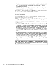
...should be corrupted during transmission. 1-8 Dell PowerEdge 2200 Systems Service Manual CAUTION: When you install or remove a termination jumper, do not move or remove any other jumpers installed on the drives or data may be configured as SCSI ID 0. • The drive you intend to use the following ...termination-no requirement that SCSI ID numbers be assigned sequentially or that termination be located on the Dell-supplied 2-gigabyte (GB), 4-GB, and 9-GB SCSI hard-disk drives for the PowerEdge 2200 system. • If you install an optional SCSI controller card to any of whether you ...
...should be corrupted during transmission. 1-8 Dell PowerEdge 2200 Systems Service Manual CAUTION: When you install or remove a termination jumper, do not move or remove any other jumpers installed on the drives or data may be configured as SCSI ID 0. • The drive you intend to use the following ...termination-no requirement that SCSI ID numbers be assigned sequentially or that termination be located on the Dell-supplied 2-gigabyte (GB), 4-GB, and 9-GB SCSI hard-disk drives for the PowerEdge 2200 system. • If you install an optional SCSI controller card to any of whether you ...

Service Manual
Page 17
termination jumper CD-ROM drive (end view) jumpered unjumpered Seagate 2-, 4-, and 9-GB hard-disk drives (bottom view) termination jumper termination jumper Western Digital 2-GB and 4-GB hard-disk drive (end view) Figure 1-5. SCSI Termination Jumper Examples System Overview 1-9
termination jumper CD-ROM drive (end view) jumpered unjumpered Seagate 2-, 4-, and 9-GB hard-disk drives (bottom view) termination jumper termination jumper Western Digital 2-GB and 4-GB hard-disk drive (end view) Figure 1-5. SCSI Termination Jumper Examples System Overview 1-9
Service Manual
Page 20
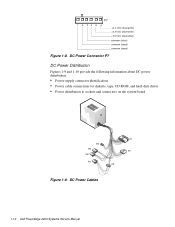
P7 1 2 34 5 6 +3.3 VDC (blue/white) +3.3 VDC (blue/white) +3.3 VDC (blue/white) common (black) common (black) common (black) Figure 1-8. DC Power Connector P7 DC Power Distribution Figures 1-9 and 1-10 provide the following information about DC power distribution: • Power-supply connector identification • Power cable connections for diskette, tape, CD-ROM, and hard-disk drives • Power distribution to sockets and connectors on the system board P1 P4 P5 P7 P6 P3 P2 Figure 1-9. DC Power Cables 1-12 Dell PowerEdge 2200 Systems Service Manual
P7 1 2 34 5 6 +3.3 VDC (blue/white) +3.3 VDC (blue/white) +3.3 VDC (blue/white) common (black) common (black) common (black) Figure 1-8. DC Power Connector P7 DC Power Distribution Figures 1-9 and 1-10 provide the following information about DC power distribution: • Power-supply connector identification • Power cable connections for diskette, tape, CD-ROM, and hard-disk drives • Power distribution to sockets and connectors on the system board P1 P4 P5 P7 P6 P3 P2 Figure 1-9. DC Power Cables 1-12 Dell PowerEdge 2200 Systems Service Manual

Service Manual
Page 21
... PCI6 +5 VDC -5 VDC +12 VDC -12 VDC battery (+3 VDC) +3.3 VDC +5 VFP PWRGOOD EISA1 through EISA3 SRV_MGT optional P2 drive CD-ROM P3 drive P4 3.5-inch diskette drive P5 internal hard-disk drive P6 internal hard-disk drive internal hard-disk drive Y-cable main memory sockets DIMM_D DIMM_C DIMM_B DIMM_A PROC_1 +12 VDC +5 VFP +5 VDC fuse +5 VDC +5 VDC processor core...
... PCI6 +5 VDC -5 VDC +12 VDC -12 VDC battery (+3 VDC) +3.3 VDC +5 VFP PWRGOOD EISA1 through EISA3 SRV_MGT optional P2 drive CD-ROM P3 drive P4 3.5-inch diskette drive P5 internal hard-disk drive P6 internal hard-disk drive internal hard-disk drive Y-cable main memory sockets DIMM_D DIMM_C DIMM_B DIMM_A PROC_1 +12 VDC +5 VFP +5 VDC fuse +5 VDC +5 VDC processor core...

Service Manual
Page 22
... [top], DIMM_B, DIMM_C, and DIMM_D) primary microprocessor module (PROC_1) secondary microprocessor module (PROC_2) hard-disk drive access indicator connector (HDLED) auxiliary fan connector (AUXFAN) configuration jumpers PCI connectors (PCI4 [bottom], PCI5, and PCI6) server management connector (SVR_MGT) 1-14 Dell PowerEdge 2200 Systems Service Manual System Board Layout The subsections that follow provide service-related information...
... [top], DIMM_B, DIMM_C, and DIMM_D) primary microprocessor module (PROC_1) secondary microprocessor module (PROC_2) hard-disk drive access indicator connector (HDLED) auxiliary fan connector (AUXFAN) configuration jumpers PCI connectors (PCI4 [bottom], PCI5, and PCI6) server management connector (SVR_MGT) 1-14 Dell PowerEdge 2200 Systems Service Manual System Board Layout The subsections that follow provide service-related information...
Service Manual
Page 28
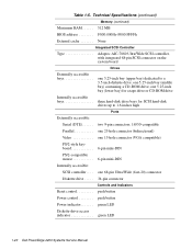
... push button Power control push button Power indicator green LED Diskette-drive access indicator green LED 1-20 Dell PowerEdge 2200 Systems Service Manual one 5.25-inch bay (middle bay) containing a CD-ROM drive; Technical Specifications (continued) Memory (continued) Maximum RAM 512 MB...: SCSI controller . . . . one 5.25-inch bay (lower bay) for a tape drive or CD-ROM drive Internally accessible bays three hard-disk drive bays for SCSI hard-disk drives up to 1.6 inches high Ports Externally accessible: Serial (DTE two 9-pin connectors; 16550-compatible Parallel...
... push button Power control push button Power indicator green LED Diskette-drive access indicator green LED 1-20 Dell PowerEdge 2200 Systems Service Manual one 5.25-inch bay (middle bay) containing a CD-ROM drive; Technical Specifications (continued) Memory (continued) Maximum RAM 512 MB...: SCSI controller . . . . one 5.25-inch bay (lower bay) for a tape drive or CD-ROM drive Internally accessible bays three hard-disk drive bays for SCSI hard-disk drives up to 1.6 inches high Ports Externally accessible: Serial (DTE two 9-pin connectors; 16550-compatible Parallel...
Service Manual
Page 29
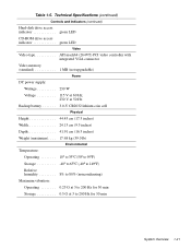
Technical Specifications (continued) Controls and Indicators (continued) Hard-disk drive access indicator green LED CD-ROM drive access indicator green LED Video Video type ATI mach64 (264VT) PCI video controller with integrated VGA connector Video memory (standard 1 MB (not upgradable) Power DC ...
Technical Specifications (continued) Controls and Indicators (continued) Hard-disk drive access indicator green LED CD-ROM drive access indicator green LED Video Video type ATI mach64 (264VT) PCI video controller with integrated VGA connector Video memory (standard 1 MB (not upgradable) Power DC ...
Service Manual
Page 31
... perform the following procedures in the order they are presented in the User's Guide provides information about backing up any data on the hard-disk drive if the system's condition permits. Yes. No. Observe the user to determine if he or she is making an error, such ... you diagnose a computer system problem. Ask the user to describe the problem and the conditions under which it occurs. Proceed to step 3. Yes. Dell recommends that can often indicate the cause of user error? Appendix C, "Maintaining the System," in this chapter. Instruct the user in this manual. ...
... perform the following procedures in the order they are presented in the User's Guide provides information about backing up any data on the hard-disk drive if the system's condition permits. Yes. No. Observe the user to determine if he or she is making an error, such ... you diagnose a computer system problem. Ask the user to describe the problem and the conditions under which it occurs. Proceed to step 3. Yes. Dell recommends that can often indicate the cause of user error? Appendix C, "Maintaining the System," in this chapter. Instruct the user in this manual. ...

Service Manual
Page 34
...has saved all open application programs if possible. If a system error message is displayed, see Table 3-2. • Diskette-drive and hard-disk drive access indicators: These indicators light up during system operations. WARNING: Before beginning to the next section, "Internal Visual Inspection."... microprocessor(s) modules, are fully seated in this chapter. When you proceed with a metal surface on the chassis. 2-4 Dell PowerEdge 2200 Systems Service Manual WARNING: While reseating the microprocessor module, wear a wrist grounding strap or maintain contact with the internal visual...
...has saved all open application programs if possible. If a system error message is displayed, see Table 3-2. • Diskette-drive and hard-disk drive access indicators: These indicators light up during system operations. WARNING: Before beginning to the next section, "Internal Visual Inspection."... microprocessor(s) modules, are fully seated in this chapter. When you proceed with a metal surface on the chassis. 2-4 Dell PowerEdge 2200 Systems Service Manual WARNING: While reseating the microprocessor module, wear a wrist grounding strap or maintain contact with the internal visual...
Service Manual
Page 40
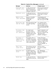
... keyboard, key- Memory size limit exceeded The size of installed DIMM memory is not installed in drive A, or load a bootable operating system from the hard-disk drive. Operating system not found The system did not find a bootable operating system. Processor X temperature sensor...keyboard, keyboard cable, or system board. Use a diskette with a bootable operating system on the system board malfunctioned. faulty. 3-4 Dell PowerEdge 2200 Systems Service Manual Defective microprocessor or system board. Install a terminator card in Chapter 4. Stuck key A cable may be loose, ...
... keyboard, key- Memory size limit exceeded The size of installed DIMM memory is not installed in drive A, or load a bootable operating system from the hard-disk drive. Operating system not found The system did not find a bootable operating system. Processor X temperature sensor...keyboard, keyboard cable, or system board. Use a diskette with a bootable operating system on the system board malfunctioned. faulty. 3-4 Dell PowerEdge 2200 Systems Service Manual Defective microprocessor or system board. Install a terminator card in Chapter 4. Stuck key A cable may be loose, ...
Service Manual
Page 50
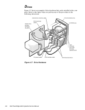
Refer to this figure when you perform any of drive hardware that can be installed in the following subsections. diskette drive interface cable diskette drive interface connector (FLOPPY) SCSI connector (SCSI) 3.5-inch diskette drive CD-ROM drive DC power cables SCSI interface cable Figure 4-7. Drives Figure 4-7 shows an example of the procedures in the computer. Drive Hardware lower externally accessible drive bay (optional drive) SCSI hard-disk drives 4-8 Dell PowerEdge 2200 Systems Service Manual
Refer to this figure when you perform any of drive hardware that can be installed in the following subsections. diskette drive interface cable diskette drive interface connector (FLOPPY) SCSI connector (SCSI) 3.5-inch diskette drive CD-ROM drive DC power cables SCSI interface cable Figure 4-7. Drives Figure 4-7 shows an example of the procedures in the computer. Drive Hardware lower externally accessible drive bay (optional drive) SCSI hard-disk drives 4-8 Dell PowerEdge 2200 Systems Service Manual

Service Manual
Page 53
... bracket. 6. Hard-Disk Drives hard-disk drive hard-disk drive bracket alignment rails left alignment tab hard-disk drive mounting screws (4) right alignment tab (on its right side. 2. Remove the four mounting screws that attach the hard-disk drive bracket to the settings you position the hard-disk drive against the side and back tabs inside a hard-disk drive bracket. Slide the hard-disk drive bracket...
... bracket. 6. Hard-Disk Drives hard-disk drive hard-disk drive bracket alignment rails left alignment tab hard-disk drive mounting screws (4) right alignment tab (on its right side. 2. Remove the four mounting screws that attach the hard-disk drive bracket to the settings you position the hard-disk drive against the side and back tabs inside a hard-disk drive bracket. Slide the hard-disk drive bracket...


