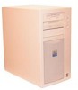

Service Manual
Page 3
Contents Chapter 1 System Overview 1-1 System Features 1-1 System Memory 1-5 Advanced Expansion Subsystem 1-6 Integrated Server Management 1-6 Video Controller 1-6 Integrated SCSI Controller 1-6 SCSI Hard-Disk Drives 1-7 SCSI Configuration Guidelines 1-7 SCSI ID Numbers 1-7 Device Termination 1-8 System Unit 1-10 System Power Supply 1-10 Pin Assignments for the DC Power Connectors 1-10 DC Power Distribution 1-12 System Board Layout 1-14 System Board Jumpers 1-15 Interrupt Assignments 1-17 DMA Channel Assignments 1-18 Technical Specifications 1-19 v
Contents Chapter 1 System Overview 1-1 System Features 1-1 System Memory 1-5 Advanced Expansion Subsystem 1-6 Integrated Server Management 1-6 Video Controller 1-6 Integrated SCSI Controller 1-6 SCSI Hard-Disk Drives 1-7 SCSI Configuration Guidelines 1-7 SCSI ID Numbers 1-7 Device Termination 1-8 System Unit 1-10 System Power Supply 1-10 Pin Assignments for the DC Power Connectors 1-10 DC Power Distribution 1-12 System Board Layout 1-14 System Board Jumpers 1-15 Interrupt Assignments 1-17 DMA Channel Assignments 1-18 Technical Specifications 1-19 v

Service Manual
Page 14
...768 pixels (256 colors). Maximum noninterlaced resolutions are located on the system board (see "Adding Memory" in Chapter 7 of the Dell PowerEdge 2200 Systems User's Guide. Integrated SCSI Controller A single integrated SCSI controller provides an Ultra/Wide (fast-20) SCSI interface through a...lower externally accessible drive bay. 1-6 Dell PowerEdge 2200 Systems Service Manual The video controller is rebooted. The six expansion-card slots include three EISA expansion-card connectors and three PCI expansion-card connectors. The EISA Configuration Utility included with the system provides...
...768 pixels (256 colors). Maximum noninterlaced resolutions are located on the system board (see "Adding Memory" in Chapter 7 of the Dell PowerEdge 2200 Systems User's Guide. Integrated SCSI Controller A single integrated SCSI controller provides an Ultra/Wide (fast-20) SCSI interface through a...lower externally accessible drive bay. 1-6 Dell PowerEdge 2200 Systems Service Manual The video controller is rebooted. The six expansion-card slots include three EISA expansion-card connectors and three PCI expansion-card connectors. The EISA Configuration Utility included with the system provides...
Service Manual
Page 15
.... NOTE: Any narrow SCSI devices installed in the User's Guide. The SCSI hard-disk drive bays are populated from Dell, the default SCSI ID numbers are assigned as other devices, their configuration requirements are shipped from left to the built-in SCSI controller (no CD-ROM or tape drives), the controller may...
.... NOTE: Any narrow SCSI devices installed in the User's Guide. The SCSI hard-disk drive bays are populated from Dell, the default SCSI ID numbers are assigned as other devices, their configuration requirements are shipped from left to the built-in SCSI controller (no CD-ROM or tape drives), the controller may...
Service Manual
Page 16
... There is no action is required. • Termination is set on the drives or data may be corrupted during transmission. 1-8 Dell PowerEdge 2200 Systems Service Manual Therefore, regardless of the internal drive bays when the drive is installed by ID number. See the documentation that ...not move or remove any other SCSI device in the externally accessible drive bays, you must configure the termination on the Dell-supplied 2-gigabyte (GB), 4-GB, and 9-GB SCSI hard-disk drives for the PowerEdge 2200 system. • If you install an optional SCSI controller card to control the CD-ROM...
... There is no action is required. • Termination is set on the drives or data may be corrupted during transmission. 1-8 Dell PowerEdge 2200 Systems Service Manual Therefore, regardless of the internal drive bays when the drive is installed by ID number. See the documentation that ...not move or remove any other SCSI device in the externally accessible drive bays, you must configure the termination on the Dell-supplied 2-gigabyte (GB), 4-GB, and 9-GB SCSI hard-disk drives for the PowerEdge 2200 system. • If you install an optional SCSI controller card to control the CD-ROM...

Service Manual
Page 22
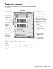
...) primary microprocessor module (PROC_1) secondary microprocessor module (PROC_2) hard-disk drive access indicator connector (HDLED) auxiliary fan connector (AUXFAN) configuration jumpers PCI connectors (PCI4 [bottom], PCI5, and PCI6) server management connector (SVR_MGT) 1-14 Dell PowerEdge 2200 Systems Service Manual diskette controller connector (FLOPPY) fan connector (FAN) keyboard (bottom) and mouse (top) connectors (KYBD/MOUSE...
...) primary microprocessor module (PROC_1) secondary microprocessor module (PROC_2) hard-disk drive access indicator connector (HDLED) auxiliary fan connector (AUXFAN) configuration jumpers PCI connectors (PCI4 [bottom], PCI5, and PCI6) server management connector (SVR_MGT) 1-14 Dell PowerEdge 2200 Systems Service Manual diskette controller connector (FLOPPY) fan connector (FAN) keyboard (bottom) and mouse (top) connectors (KYBD/MOUSE...
Service Manual
Page 24
...boot password feature. Enables/disables integrated video controller Boots from BIOS. 1-16 Dell PowerEdge 2200 Systems Service Manual Remove jumper to allow normal boot operation from BIOS card Remove jumper and use EISA Configuration Utility to configure system. Jumper RSVD2 RSVD1 266MHZ 233MHZ PASSWD EISA VGA CARDBIOS Table 1-2. For... speed is 266 MHz. Install jumper to clear configura- Jumper Descriptions Description Settings For future microprocessor Reserved. Clears EISA configuration Install jumper and boot settings system to boot system from BIOS expansion card.
...boot password feature. Enables/disables integrated video controller Boots from BIOS. 1-16 Dell PowerEdge 2200 Systems Service Manual Remove jumper to allow normal boot operation from BIOS card Remove jumper and use EISA Configuration Utility to configure system. Jumper RSVD2 RSVD1 266MHZ 233MHZ PASSWD EISA VGA CARDBIOS Table 1-2. For... speed is 266 MHz. Install jumper to clear configura- Jumper Descriptions Description Settings For future microprocessor Reserved. Clears EISA configuration Install jumper and boot settings system to boot system from BIOS expansion card.
Service Manual
Page 35
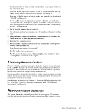
...in Chapter 4. If you suspect that aid in Chapter 1. Check all jumpers are fully seated in their sockets, press firmly on the Dell Server Assistant CD) contains tests that resource conflicts might exist, check the system and reassign the resources as described in "Expansion Cards" in... and reinstall it in disorderly or erratic system operation or system failure. For information about these jumpers, see Chapter 5, "Using the EISA Configuration Utility," in the User's Guide or "Interrupt Assignments" and "DMA Channel Assignments" in troubleshooting all of which must be resolved? To ...
...in Chapter 4. If you suspect that aid in Chapter 1. Check all jumpers are fully seated in their sockets, press firmly on the Dell Server Assistant CD) contains tests that resource conflicts might exist, check the system and reassign the resources as described in "Expansion Cards" in... and reinstall it in disorderly or erratic system operation or system failure. For information about these jumpers, see Chapter 5, "Using the EISA Configuration Utility," in the User's Guide or "Interrupt Assignments" and "DMA Channel Assignments" in troubleshooting all of which must be resolved? To ...
Service Manual
Page 39
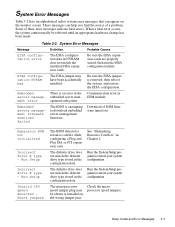
... speed jumper plug may have been accidentally installed. System Error Messages Message Definition Probable Causes EISA configuration error The EISA configuration data in the server manage- EISA configuration NVRAM bad The EISA jumper may be rebooted until an appropriate hardware change has been made....not match the installed EISA expansion cards. Run Setup Invalid CPU speed detected Check jumpers The BIOS detected a resource conflict while configuring a Plug and Play ISA or PCI expansion card. Run the System Setup program to download embedded server management firmware. Beep...
... speed jumper plug may have been accidentally installed. System Error Messages Message Definition Probable Causes EISA configuration error The EISA configuration data in the server manage- EISA configuration NVRAM bad The EISA jumper may be rebooted until an appropriate hardware change has been made....not match the installed EISA expansion cards. Run Setup Invalid CPU speed detected Check jumpers The BIOS detected a resource conflict while configuring a Plug and Play ISA or PCI expansion card. Run the System Setup program to download embedded server management firmware. Beep...
Service Manual
Page 40
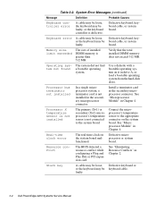
... microprocessor system, a terminator card is greater than 512 MB. See "Microprocessor Module" in the secondary microprocessor connector. faulty. 3-4 Dell PowerEdge 2200 Systems Service Manual Table 3-2. Defective keyboard, keyboard cable, or system board. or the keyboard may be faulty, or the keyboard ...512 MB. Connect the microprocessor's temperature sensor to the system board. Resource conflict The BIOS detected a resource conflict while configuring a Plug and Play ISA or PCI expansion card. Stuck key A cable may be loose, Defective keyboard or or the...
... microprocessor system, a terminator card is greater than 512 MB. See "Microprocessor Module" in the secondary microprocessor connector. faulty. 3-4 Dell PowerEdge 2200 Systems Service Manual Table 3-2. Defective keyboard, keyboard cable, or system board. or the keyboard may be faulty, or the keyboard ...512 MB. Connect the microprocessor's temperature sensor to the system board. Resource conflict The BIOS detected a resource conflict while configuring a Plug and Play ISA or PCI expansion card. Stuck key A cable may be loose, Defective keyboard or or the...
Service Manual
Page 41
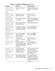
... or replace the DIMMs. System timer error A chip on the system board. Move the microprocessor to restore your system configuration. write error Defective system board. Replace the battery and run Setup The system battery is faulty. System CMOS checksum bad...Microprocessor Module" in Chapter 2. System memory size has changed - Warning: IRQ not initialized The BIOS detected a resource conflict while configuring a Plug and Play ISA or PCI expansion card. System Error Messages (continued) Message Definition Probable Causes System battery is connected to...
... or replace the DIMMs. System timer error A chip on the system board. Move the microprocessor to restore your system configuration. write error Defective system board. Replace the battery and run Setup The system battery is faulty. System CMOS checksum bad...Microprocessor Module" in Chapter 2. System memory size has changed - Warning: IRQ not initialized The BIOS detected a resource conflict while configuring a Plug and Play ISA or PCI expansion card. System Error Messages (continued) Message Definition Probable Causes System battery is connected to...
Service Manual
Page 57
... (DIMM_A [top], DIMM_B, DIMM_C, and DIMM_D) primary microprocessor module (PROC_1) secondary microprocessor module (PROC_2) hard-disk drive access indicator connector (HDLED) auxiliary fan connector (AUXFAN) configuration jumpers PCI connectors (PCI4 [bottom], PCI5, and PCI6) server management connector (SVR_MGT) DIMMs NOTE: Use care when removing or replacing DIMMs. The available area of...
... (DIMM_A [top], DIMM_B, DIMM_C, and DIMM_D) primary microprocessor module (PROC_1) secondary microprocessor module (PROC_2) hard-disk drive access indicator connector (HDLED) auxiliary fan connector (AUXFAN) configuration jumpers PCI connectors (PCI4 [bottom], PCI5, and PCI6) server management connector (SVR_MGT) DIMMs NOTE: Use care when removing or replacing DIMMs. The available area of...

Service Manual
Page 60
... mounting plate tabs (2) front of the computer to free the assembly from the tabs (see Figure 4-19). 4-18 Dell PowerEdge 2200 Systems Service Manual Raise the top of the system board assembly up enough to allow access to cool before touching it ...indicator cable, system cooling-fan cables, and SCSI interface cable. 6. 5. Remove the microprocessor module. Write down or print out the system configuration information in the EISA Configuration Utility. 2. Remove the system board assembly from the computer chassis. c. Remove the system board assembly. 3. Be sure it . Slide...
... mounting plate tabs (2) front of the computer to free the assembly from the tabs (see Figure 4-19). 4-18 Dell PowerEdge 2200 Systems Service Manual Raise the top of the system board assembly up enough to allow access to cool before touching it ...indicator cable, system cooling-fan cables, and SCSI interface cable. 6. 5. Remove the microprocessor module. Write down or print out the system configuration information in the EISA Configuration Utility. 2. Remove the system board assembly from the computer chassis. c. Remove the system board assembly. 3. Be sure it . Slide...

Service Manual
Page 62
... microprocessor module straight up and out of the microprocessor retention bracket on the system board (see the next subsection, "Terminator Card"). 4-20 Dell PowerEdge 2200 Systems Service Manual Run the EISA Configuration Utility to verify that the Processor 1 and Processor 2 categories correctly identify the installed microprocessor(s). microprocessor retention bracket Figure 4-21. Removing a Microprocessor Module...
... microprocessor module straight up and out of the microprocessor retention bracket on the system board (see the next subsection, "Terminator Card"). 4-20 Dell PowerEdge 2200 Systems Service Manual Run the EISA Configuration Utility to verify that the Processor 1 and Processor 2 categories correctly identify the installed microprocessor(s). microprocessor retention bracket Figure 4-21. Removing a Microprocessor Module...

Service Manual
Page 65
..., nonconducting object, such as a plastic screwdriver. Restore any expansion cards installed in step 1. System Battery Removal WARNING: There is a danger of the system configuration settings you made in the PCI expansion-card slots. To remove the system battery, follow these steps: 1. If possible, enter the System Setup program, and... removed. 4. Discard used batteries according to the system board until the microprocessor retention bracket can be removed (see Appendix A). 2. Remove any system configuration information lost while replacing the battery. Removing and Replacing Parts 4-23
..., nonconducting object, such as a plastic screwdriver. Restore any expansion cards installed in step 1. System Battery Removal WARNING: There is a danger of the system configuration settings you made in the PCI expansion-card slots. To remove the system battery, follow these steps: 1. If possible, enter the System Setup program, and... removed. 4. Discard used batteries according to the system board until the microprocessor retention bracket can be removed (see Appendix A). 2. Remove any system configuration information lost while replacing the battery. Removing and Replacing Parts 4-23
Service Manual
Page 67
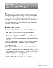
... too long, the operating system begins to the left of the selection. Contains system reference information and menu bar selections • Configuration options and system data box - System Setup Screens The System Setup program is positioned • Key functions box - Provides detailed ...settings for some selections have four boxed-in NVRAM on self-tests. Contains configuration selec- Displays item-specific help for the item where the cursor is a menu-driven program. Provides settings for four menus, they are...
... too long, the operating system begins to the left of the selection. Contains system reference information and menu bar selections • Configuration options and system data box - System Setup Screens The System Setup program is positioned • Key functions box - Provides detailed ...settings for some selections have four boxed-in NVRAM on self-tests. Contains configuration selec- Displays item-specific help for the item where the cursor is a menu-driven program. Provides settings for four menus, they are...

Service Manual
Page 68
... the field Selects a higher value for the field Loads the default configuration values for this menu Loads the default configuration values for all setup items Loads the previous configuration values for this menu Executes the selected command or displays a submenu Refreshes the screen A-2 Dell PowerEdge 2200 Systems Service Manual Table A-1. Key Function Box Table A-1 lists the...
... the field Selects a higher value for the field Loads the default configuration values for this menu Loads the default configuration values for all setup items Loads the previous configuration values for this menu Executes the selected command or displays a submenu Refreshes the screen A-2 Dell PowerEdge 2200 Systems Service Manual Table A-1. Key Function Box Table A-1 lists the...

Service Manual
Page 69
... the color of the field also identifies the type of the screen. • Blue on white - The hightlight color for help box title box Dell System PowerEdge 2200 Setup Main Advanced Security Exit Time: [5:01:96] Date: [June 04, 1997] Diskette Drive A: [1.44 MB, 3.5 inch] Diskette Drive B:... then C:] Numlock: [On] Speaker: [On] BIOS Version AXX Item Specific Help Resets the time on the computer's internal clock. Main Menu configuration options and system data box help messages. • Bright white on white - Headers and footers, including the title box at the top of the...
... the color of the field also identifies the type of the screen. • Blue on white - The hightlight color for help box title box Dell System PowerEdge 2200 Setup Main Advanced Security Exit Time: [5:01:96] Date: [June 04, 1997] Diskette Drive A: [1.44 MB, 3.5 inch] Diskette Drive B:... then C:] Numlock: [On] Speaker: [On] BIOS Version AXX Item Specific Help Resets the time on the computer's internal clock. Main Menu configuration options and system data box help messages. • Bright white on white - Headers and footers, including the title box at the top of the...

Service Manual
Page 72
... [AUTO] [AUTO] [378, IRQ 7] [Output only] [Enabled] [Enabled] [Slot devices first] [1.4] [Enabled] BIOS Version AXX Item Specific Help Configures the system's built-in serial port. F1 Help ESC Exit Select Item Select Menu -/+ Change Values Enter Select Sub-Menu F9 Setup Defaults F10 Previous Values Figure A-3. Advanced Menu A-6 Dell PowerEdge 2200 Systems Service Manual
... [AUTO] [AUTO] [378, IRQ 7] [Output only] [Enabled] [Enabled] [Slot devices first] [1.4] [Enabled] BIOS Version AXX Item Specific Help Configures the system's built-in serial port. F1 Help ESC Exit Select Item Select Menu -/+ Change Values Enter Select Sub-Menu F9 Setup Defaults F10 Previous Values Figure A-3. Advanced Menu A-6 Dell PowerEdge 2200 Systems Service Manual

Service Manual
Page 73
.... Advanced Menu Categories Category Function Serial Port 1 Selects a unique address and interrupt request for Serial Port 2. Options are scanned. and Auto (default). Use MP Specifications Configures the Multiprocessor Specification level. Auto selects the next available combination. Parallel Port Selects a unique address and interrupt request for LPT Port.
.... Advanced Menu Categories Category Function Serial Port 1 Selects a unique address and interrupt request for Serial Port 2. Options are scanned. and Auto (default). Use MP Specifications Configures the Multiprocessor Specification level. Auto selects the next available combination. Parallel Port Selects a unique address and interrupt request for LPT Port.

Service Manual
Page 77
... stored in CMOS. Exit Menu Categories Category Function Save Changes & Exit Saves the changes you have made before you boot up your system, the BIOS configures your changes in the System Setup program. Exit Without Saving Changes Exits the System Setup program without saving any of the changes you have made...
... stored in CMOS. Exit Menu Categories Category Function Save Changes & Exit Saves the changes you have made before you boot up your system, the BIOS configures your changes in the System Setup program. Exit Without Saving Changes Exits the System Setup program without saving any of the changes you have made...

