Service Manual
Page 4
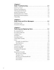
... 2-4 Eliminating Resource Conflicts 2-5 Running the System Diagnostics 2-5 Getting Help 2-6 Chapter 3 Beep Codes and Error Messages 3-1 POST Beep Codes 3-1 System Error Messages 3-3 Chapter 4 Removing and Replacing Parts 4-1 Recommended Tools 4-1 Precautionary Measures 4-2 Computer Cover 4-3 Front Bezel 4-4 Front-Bezel Inserts 4-5 Control Panel Assembly 4-7 Drives 4-8 Externally Accessible Drives 4-9 Hard-Disk Drives 4-11 Expansion Cards 4-12...
... 2-4 Eliminating Resource Conflicts 2-5 Running the System Diagnostics 2-5 Getting Help 2-6 Chapter 3 Beep Codes and Error Messages 3-1 POST Beep Codes 3-1 System Error Messages 3-3 Chapter 4 Removing and Replacing Parts 4-1 Recommended Tools 4-1 Precautionary Measures 4-2 Computer Cover 4-3 Front Bezel 4-4 Front-Bezel Inserts 4-5 Control Panel Assembly 4-7 Drives 4-8 Externally Accessible Drives 4-9 Hard-Disk Drives 4-11 Expansion Cards 4-12...
Service Manual
Page 33
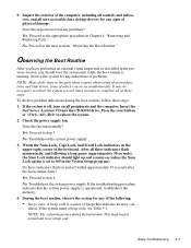
...after the boot routine starts? Proceed to the appropriate procedure in order to reboot the system several times in Chapter 4, "Removing and Replacing Parts." This single beep is normal and is a series of the computer, including all controls and indicators, and all of which can occur...an external visual inspection as described in this procedure require observation of system functions and indications, some of these steps. No. Insert the Dell Server Assistant CD into the CD-ROM drive. Yes. Troubleshoot the system power supply. 3. Press the reset button or to step 4....
...after the boot routine starts? Proceed to the appropriate procedure in order to reboot the system several times in Chapter 4, "Removing and Replacing Parts." This single beep is normal and is a series of the computer, including all controls and indicators, and all of which can occur...an external visual inspection as described in this procedure require observation of system functions and indications, some of these steps. No. Insert the Dell Server Assistant CD into the CD-ROM drive. Yes. Troubleshoot the system power supply. 3. Press the reset button or to step 4....
Service Manual
Page 43
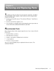
...one or more of the procedures in this chapter. • You have removed the computer cover. • You can replace or reinstall a part by performing the removal procedure in reverse order unless additional information is provided. Recommended Tools Most of the following tools: • Small flat-... nutdriver • Tweezers or long-nose pliers Also, use a wrist grounding strap as explained in the computer. Chapter 4 Removing and Replacing Parts This chapter provides procedures for removing the components, assemblies, and subassemblies in the next section, "Precautionary Measures."
...one or more of the procedures in this chapter. • You have removed the computer cover. • You can replace or reinstall a part by performing the removal procedure in reverse order unless additional information is provided. Recommended Tools Most of the following tools: • Small flat-... nutdriver • Tweezers or long-nose pliers Also, use a wrist grounding strap as explained in the computer. Chapter 4 Removing and Replacing Parts This chapter provides procedures for removing the components, assemblies, and subassemblies in the next section, "Precautionary Measures."
Service Manual
Page 45
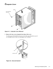
Computer Cover cover-mounting screws (4) handle Figure 4-1. Remove the four screws along the back edge of the cover-mounting screw locations. Use the key provided with the system to remove the special keylock screw if it is installed in one of the cover. Security Keylock Removing and Replacing Parts 4-3 Computer Cover Removal 1. key keylock screw Figure 4-2.
Computer Cover cover-mounting screws (4) handle Figure 4-1. Remove the four screws along the back edge of the cover-mounting screw locations. Use the key provided with the system to remove the special keylock screw if it is installed in one of the cover. Security Keylock Removing and Replacing Parts 4-3 Computer Cover Removal 1. key keylock screw Figure 4-2.

Service Manual
Page 47
... bezel facing you, grasp the front bezel with both hands and place your fingers on the outside of the insert in Figure 4-4); Removing and Replacing Parts 4-5 then twist the sides of the plastic insert (indicated by the two arrows in place under the latch. Remove the front bezel. 2. Plastic Insert Removal...
... bezel facing you, grasp the front bezel with both hands and place your fingers on the outside of the insert in Figure 4-4); Removing and Replacing Parts 4-5 then twist the sides of the plastic insert (indicated by the two arrows in place under the latch. Remove the front bezel. 2. Plastic Insert Removal...

Service Manual
Page 49
... of the computer chassis. 3. Remove the control-panel assembly cable from the PANEL connector on the right side of the computer chassis. 2. Removing and Replacing Parts 4-7 Control-Panel Assembly Removal 1. The PANEL connector is near the top of computer chassis tabs (2) Figure 4-6. Disconnect the control-panel assembly cable from the hole...
... of the computer chassis. 3. Remove the control-panel assembly cable from the PANEL connector on the right side of the computer chassis. 2. Removing and Replacing Parts 4-7 Control-Panel Assembly Removal 1. The PANEL connector is near the top of computer chassis tabs (2) Figure 4-6. Disconnect the control-panel assembly cable from the hole...

Service Manual
Page 51
... remove a drive assembly from the drive (see Figure 4-9). 4. If the drive is a SCSI drive, record the setting of the interface cable connector. 2. Removing and Replacing Parts 4-9 Press inward (toward center of drive) on the two drive-release tabs, and slide the drive out of the drive. Disconnect the DC power cable...
... remove a drive assembly from the drive (see Figure 4-9). 4. If the drive is a SCSI drive, record the setting of the interface cable connector. 2. Removing and Replacing Parts 4-9 Press inward (toward center of drive) on the two drive-release tabs, and slide the drive out of the drive. Disconnect the DC power cable...

Service Manual
Page 53
...). To remove a hard-disk drive, follow these steps: 1. Disconnect the DC power cable and the SCSI interface cable from the alignment rails; Removing and Replacing Parts 4-11 Slide the hard-disk drive bracket toward the back of the computer until the alignment tabs disengage from the back of the computer chassis...
...). To remove a hard-disk drive, follow these steps: 1. Disconnect the DC power cable and the SCSI interface cable from the alignment rails; Removing and Replacing Parts 4-11 Slide the hard-disk drive bracket toward the back of the computer until the alignment tabs disengage from the back of the computer chassis...

Service Manual
Page 55
... the AC power cable from the system board (see Figure 4-14), the externally accessible drives, and the hard-disk drives (see Figure 4-7). Removing and Replacing Parts 4-13 then lift it out of the power supply engage the retaining tabs on the computer chassis. Disconnect the DC power cables from the AC...
... the AC power cable from the system board (see Figure 4-14), the externally accessible drives, and the hard-disk drives (see Figure 4-7). Removing and Replacing Parts 4-13 then lift it out of the power supply engage the retaining tabs on the computer chassis. Disconnect the DC power cables from the AC...
Service Manual
Page 56
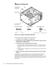
... cooling fan, use four new push-fasteners. (New pushfasteners have the plunger inserted part-way into the barrel.) Align the mounting holes in the system cooling fan with the holes in the plunger to lock the fastener. 4-14 Dell PowerEdge 2200 Systems Service Manual System Cooling-Fan Removal system cooling fan To remove the...
... cooling fan, use four new push-fasteners. (New pushfasteners have the plunger inserted part-way into the barrel.) Align the mounting holes in the system cooling fan with the holes in the plunger to lock the fastener. 4-14 Dell PowerEdge 2200 Systems Service Manual System Cooling-Fan Removal system cooling fan To remove the...
Service Manual
Page 57
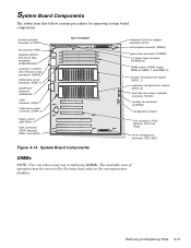
...) EISA connectors (EISA1 [bottom], EISA2, and EISA3) top of operation may be restricted by the large heat sinks on the microprocessor modules. Removing and Replacing Parts 4-15 System Board Components integrated SCSI host adapter connector (SCSI) control-panel connector (PANEL) power input connector (POWER) 3-V power input connector (POWER3V) DIMM sockets (DIMM_A...
...) EISA connectors (EISA1 [bottom], EISA2, and EISA3) top of operation may be restricted by the large heat sinks on the microprocessor modules. Removing and Replacing Parts 4-15 System Board Components integrated SCSI host adapter connector (SCSI) control-panel connector (PANEL) power input connector (POWER) 3-V power input connector (POWER3V) DIMM sockets (DIMM_A...
Service Manual
Page 59
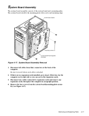
... the computer. system board cables mounting screws (4) system board/mounting plate assembly Figure 4-17. then place the computer in an upright position. 4. Removing and Replacing Parts 4-17 Be sure to record where each cable is held to the mounting plate with screws and mounting clips. Disconnect any expansion cards; Disconnect all...
... the computer. system board cables mounting screws (4) system board/mounting plate assembly Figure 4-17. then place the computer in an upright position. 4. Removing and Replacing Parts 4-17 Be sure to record where each cable is held to the mounting plate with screws and mounting clips. Disconnect any expansion cards; Disconnect all...
Service Manual
Page 61
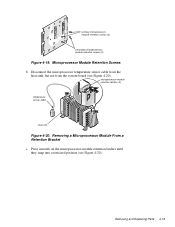
... 4-20). primary microprocessormodule retention screws (2) secondary microprocessormodule retention screws (2) Figure 4-19. microprocessor-module retention latches (2) temperature sensor cable heat sink Figure 4-20. Removing and Replacing Parts 4-19 Disconnect the microprocessor temperature sensor cable from the heat sink, but not from the system board (see Figure 4-20). Removing a Microprocessor Module From a Retention...
... 4-20). primary microprocessormodule retention screws (2) secondary microprocessormodule retention screws (2) Figure 4-19. microprocessor-module retention latches (2) temperature sensor cable heat sink Figure 4-20. Removing and Replacing Parts 4-19 Disconnect the microprocessor temperature sensor cable from the heat sink, but not from the system board (see Figure 4-20). Removing a Microprocessor Module From a Retention...

Service Manual
Page 63
Remove the system board assembly. 2. Using the thumb and forefinger of each hand, pinch the vertical tabs at each end of the cover, and then lift the cover straight up from the microprocessor retention bracket. Hold the card by its edges, and lift the card straight up . 3. Removing and Replacing Parts 4-21 Terminator Card Removal 1. Remove the terminator card. Terminator Card terminator card terminator-card retention bracket cover tabs (2) microprocessor retention bracket Figure 4-22. Remove the terminator-card retention bracket cover.
Remove the system board assembly. 2. Using the thumb and forefinger of each hand, pinch the vertical tabs at each end of the cover, and then lift the cover straight up from the microprocessor retention bracket. Hold the card by its edges, and lift the card straight up . 3. Removing and Replacing Parts 4-21 Terminator Card Removal 1. Remove the terminator card. Terminator Card terminator card terminator-card retention bracket cover tabs (2) microprocessor retention bracket Figure 4-22. Remove the terminator-card retention bracket cover.

Service Manual
Page 65
... System Setup program, and make a printed copy of any expansion cards installed in step 1. Be sure to the PCI cards being removed. 4. Removing and Replacing Parts 4-23 System Battery battery BATTERY socket Figure 4-25. To replace the system battery, orient the new battery with the copy of the new battery exploding...
... System Setup program, and make a printed copy of any expansion cards installed in step 1. Be sure to the PCI cards being removed. 4. Removing and Replacing Parts 4-23 System Battery battery BATTERY socket Figure 4-25. To replace the system battery, orient the new battery with the copy of the new battery exploding...


