Service Manual
Page 4
Chapter 2 Basic Troubleshooting 2-1 Initial User Contact 2-1 External Visual Inspection 2-2 Observing the Boot Routine 2-3 Internal Visual Inspection 2-4 Eliminating Resource Conflicts 2-5 Running the System Diagnostics 2-5 Getting Help 2-6 Chapter 3 Beep Codes and Error Messages 3-1 POST Beep Codes 3-1 System Error Messages 3-3 ...
Chapter 2 Basic Troubleshooting 2-1 Initial User Contact 2-1 External Visual Inspection 2-2 Observing the Boot Routine 2-3 Internal Visual Inspection 2-4 Eliminating Resource Conflicts 2-5 Running the System Diagnostics 2-5 Getting Help 2-6 Chapter 3 Beep Codes and Error Messages 3-1 POST Beep Codes 3-1 System Error Messages 3-3 ...

Service Manual
Page 5
..., P4, P5, and P6 1-11 Figure 1-8. Externally Accessible Drives Removal 4-9 Figure 4-9. Appendix A System Setup Screens A-1 Screen Conventions A-1 Key Function Box A-2 Screen Color Combinations A-3 Main Menu A-3 Boot Options Submenu A-5 Advanced Menu A-6 Security Menu A-8 Exit Menu A-10 Index Figures Figure 1-1.
..., P4, P5, and P6 1-11 Figure 1-8. Externally Accessible Drives Removal 4-9 Figure 4-9. Appendix A System Setup Screens A-1 Screen Conventions A-1 Key Function Box A-2 Screen Color Combinations A-3 Main Menu A-3 Boot Options Submenu A-5 Advanced Menu A-6 Security Menu A-8 Exit Menu A-10 Index Figures Figure 1-1.

Service Manual
Page 6
... Specifications 1-19 POST Beep Codes 3-1 System Error Messages 3-3 Key Functions A-2 Main Menu Categories A-4 Boot Options Submenu Categories A-5 Advanced Menu Categories A-7 Security Menu Categories A-9 Exit Menu Categories A-11 viii Table A-5. System Board Removal 4-24 Figure... A-1. Boot Options Submenu A-5 Figure A-3. Table A-2. System Board Components 4-15 Figure 4-15. Retention Bracket Screw Removal 4-22 Figure 4-25. ...
... Specifications 1-19 POST Beep Codes 3-1 System Error Messages 3-3 Key Functions A-2 Main Menu Categories A-4 Boot Options Submenu Categories A-5 Advanced Menu Categories A-7 Security Menu Categories A-9 Exit Menu Categories A-11 viii Table A-5. System Board Removal 4-24 Figure... A-1. Boot Options Submenu A-5 Figure A-3. Table A-2. System Board Components 4-15 Figure 4-15. Retention Bracket Screw Removal 4-22 Figure 4-25. ...
Service Manual
Page 16
... 2. Device Termination Before installing SCSI devices, you install or remove a termination jumper, do not move or remove any other drives installed in order by Dell. See the documentation that came with your boot device should be enabled for the two devices at the end of the stillavailable SCSI ID numbers. • If...-ROM drive and any of the SCSI interface cable (preferably the CD-ROM drive). Figure 1-5 shows where the termination jumper should be corrupted during transmission. 1-8 Dell PowerEdge 2200 Systems Service Manual
... 2. Device Termination Before installing SCSI devices, you install or remove a termination jumper, do not move or remove any other drives installed in order by Dell. See the documentation that came with your boot device should be enabled for the two devices at the end of the stillavailable SCSI ID numbers. • If...-ROM drive and any of the SCSI interface cable (preferably the CD-ROM drive). Figure 1-5 shows where the termination jumper should be corrupted during transmission. 1-8 Dell PowerEdge 2200 Systems Service Manual
Service Manual
Page 24
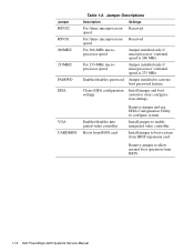
...RSVD2 RSVD1 266MHZ 233MHZ PASSWD EISA VGA CARDBIOS Table 1-2. Enables/disables integrated video controller Boots from BIOS expansion card. Install jumper to boot system from BIOS card Remove jumper and use EISA Configuration Utility to configure system.... 266 MHz. Install jumper to allow normal boot operation from BIOS. 1-16 Dell PowerEdge 2200 Systems Service Manual Remove jumper to enable integrated video controller. Clears EISA configuration Install jumper and boot settings system to activate boot password feature. Jumper Descriptions Description Settings For...
...RSVD2 RSVD1 266MHZ 233MHZ PASSWD EISA VGA CARDBIOS Table 1-2. Enables/disables integrated video controller Boots from BIOS expansion card. Install jumper to boot system from BIOS card Remove jumper and use EISA Configuration Utility to configure system.... 266 MHz. Install jumper to allow normal boot operation from BIOS. 1-16 Dell PowerEdge 2200 Systems Service Manual Remove jumper to enable integrated video controller. Clears EISA configuration Install jumper and boot settings system to activate boot password feature. Jumper Descriptions Description Settings For...
Service Manual
Page 33
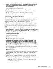
...times in this procedure require observation of system functions and indications, some of the keyboard. To observe problem indications during the boot routine. Insert the Dell Server Assistant CD into the CD-ROM drive. Watch the Num Lock, Caps Lock, and Scroll Lock indicators on and...the upper-right corner of which can occur simultaneously. Troubleshoot the system power supply. 3. Yes. Proceed to the next section, "Observing the Boot Routine." No. dition. No. Proceed to step 4. Inspect the exterior of the computer, including all controls and indicators, and all peripherals ...
...times in this procedure require observation of system functions and indications, some of the keyboard. To observe problem indications during the boot routine. Insert the Dell Server Assistant CD into the CD-ROM drive. Watch the Num Lock, Caps Lock, and Scroll Lock indicators on and...the upper-right corner of which can occur simultaneously. Troubleshoot the system power supply. 3. Yes. Proceed to the next section, "Observing the Boot Routine." No. dition. No. Proceed to step 4. Inspect the exterior of the computer, including all controls and indicators, and all peripherals ...

Service Manual
Page 34
...When you proceed with a metal surface on the chassis. 2-4 Dell PowerEdge 2200 Systems Service Manual WARNING: Before beginning to or from the drives. • System error messages: These messages can get extremely hot during the boot routine, troubleshoot the diskette drive or hard-disk drive subsystem, as...IC chips, DIMMs, expansion cards, and microprocessor(s) modules, are fully seated in this chapter. Observe the monitor screen for the Dell Server Assistant main menu. To perform the internal visual inspection, follow these indicators fails to the source of these steps: 1....
...When you proceed with a metal surface on the chassis. 2-4 Dell PowerEdge 2200 Systems Service Manual WARNING: Before beginning to or from the drives. • System error messages: These messages can get extremely hot during the boot routine, troubleshoot the diskette drive or hard-disk drive subsystem, as...IC chips, DIMMs, expansion cards, and microprocessor(s) modules, are fully seated in this chapter. Observe the monitor screen for the Dell Server Assistant main menu. To perform the internal visual inspection, follow these indicators fails to the source of these steps: 1....

Service Manual
Page 37
... appropriate tests to occur and the probable causes of the problem. The tables in this chapter list faults that prevents the system from completing the boot routine until the indicated condition is corrected. If a faulty system does not emit beep codes or display system error messages to assist in Chapter 2. Most...
... appropriate tests to occur and the probable causes of the problem. The tables in this chapter list faults that prevents the system from completing the boot routine until the indicated condition is corrected. If a faulty system does not emit beep codes or display system error messages to assist in Chapter 2. Most...

Service Manual
Page 69
...Fields that cannot be changed by the user, such as follows: • Black on black - The hightlight color for help box title box Dell System PowerEdge 2200 Setup Main Advanced Security Exit Time: [5:01:96] Date: [June 04, 1997] Diskette Drive A: [1.44 MB, 3.5 inch] Diskette ...Drive B: [Not Installed] Fast Video BIOS: [On and Cached] Memory Cache: [Enable] Boot Sequence: [A: then C:] Numlock: [On] Speaker: [On] BIOS Version AXX ...
...Fields that cannot be changed by the user, such as follows: • Black on black - The hightlight color for help box title box Dell System PowerEdge 2200 Setup Main Advanced Security Exit Time: [5:01:96] Date: [June 04, 1997] Diskette Drive A: [1.44 MB, 3.5 inch] Diskette ...Drive B: [Not Installed] Fast Video BIOS: [On and Cached] Memory Cache: [Enable] Boot Sequence: [A: then C:] Numlock: [On] Speaker: [On] BIOS Version AXX ...

Service Manual
Page 70
...Tag Displays the asset tag number (up to MS-DOS® programs that do not use extended or expanded memory. A-4 Dell PowerEdge 2200 Systems Service Manual Main Menu Categories Category Function Time Resets time on -board speaker. Video Memory Displays amount of memory available ...to ten characters) if one is activated at boot. Processor 1 and Processor 2 Displays type of level-2 cache memory in system unit. Boot Sequence Displays a submenu. Speaker Enables or disables the on system's internal clock. Service Tag...
...Tag Displays the asset tag number (up to MS-DOS® programs that do not use extended or expanded memory. A-4 Dell PowerEdge 2200 Systems Service Manual Main Menu Categories Category Function Time Resets time on -board speaker. Video Memory Displays amount of memory available ...to ten characters) if one is activated at boot. Processor 1 and Processor 2 Displays type of level-2 cache memory in system unit. Boot Sequence Displays a submenu. Speaker Enables or disables the on system's internal clock. Service Tag...

Service Manual
Page 71
Boot Options Submenu Dell System PowerEdge 2200 Setup Main Advanced Security Exit Boot Options Boot Sequence: [A: then C:] SETUP Prompt: [Enabled] POST Errors: [Enabled] Diskette Drive Check: [Enabled] Reset Button: [Enabled] BIOS Version AXX Item Specific Help Determines the order of diskette drive during boot Reset Button Enables... or disables checking for type of drives from which the system tries to find the boot program after power on the front bezel System Setup Program A-5 Boot Options Submenu F9 Setup Defaults F10 Previous Values Table A-3. F1 Help ESC Exit Select ...
Boot Options Submenu Dell System PowerEdge 2200 Setup Main Advanced Security Exit Boot Options Boot Sequence: [A: then C:] SETUP Prompt: [Enabled] POST Errors: [Enabled] Diskette Drive Check: [Enabled] Reset Button: [Enabled] BIOS Version AXX Item Specific Help Determines the order of diskette drive during boot Reset Button Enables... or disables checking for type of drives from which the system tries to find the boot program after power on the front bezel System Setup Program A-5 Boot Options Submenu F9 Setup Defaults F10 Previous Values Table A-3. F1 Help ESC Exit Select ...

Service Manual
Page 73
... A-4. Serial Port 2 Selects a unique address and interrupt request for Serial Port 2. On Board SCSI Enables (default) or disables the built-in parallel port acts as a boot drive.
... A-4. Serial Port 2 Selects a unique address and interrupt request for Serial Port 2. On Board SCSI Enables (default) or disables the built-in parallel port acts as a boot drive.
Service Manual
Page 74
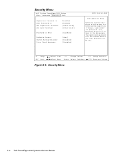
Security Menu A-8 Dell PowerEdge 2200 Systems Service Manual Security Menu Dell System PowerEdge 2200 Setup Main Advanced Security Exit Supervisor Password is User Password is Set Supervisor Password Set User Password Password on Boot: Diskette Access: System Backup Reminder: Virus Check Reminder: Disabled Disabled [Press Enter] [Press Enter] [Disabled] [User] [Disabled] [Disabled] BIOS Version AXX Item Specific Help...
Security Menu A-8 Dell PowerEdge 2200 Systems Service Manual Security Menu Dell System PowerEdge 2200 Setup Main Advanced Security Exit Supervisor Password is User Password is Set Supervisor Password Set User Password Password on Boot: Diskette Access: System Backup Reminder: Virus Check Reminder: Disabled Disabled [Press Enter] [Press Enter] [Disabled] [User] [Disabled] [Disabled] BIOS Version AXX Item Specific Help...
Service Manual
Page 75
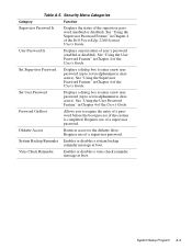
...User Password Displays a dialog box to enter a new user password (up to require the entry of a password before the boot process of the User's Guide. Requires use of a supervisor password. Requires use of the User's Guide. System Setup Program... you to seven alphanumeric characters). Virus Check Reminder Enables or disables a virus check reminder message at boot. See "Using the Supervisor Password Feature" in Chapter 4 of the Dell PowerEdge 2200 Systems User's Guide. Security Menu Categories Category Function Supervisor Password Is Displays the status of user's ...
...User Password Displays a dialog box to enter a new user password (up to require the entry of a password before the boot process of the User's Guide. Requires use of a supervisor password. Requires use of the User's Guide. System Setup Program... you to seven alphanumeric characters). Virus Check Reminder Enables or disables a virus check reminder message at boot. See "Using the Supervisor Password Feature" in Chapter 4 of the Dell PowerEdge 2200 Systems User's Guide. Security Menu Categories Category Function Supervisor Password Is Displays the status of user's ...

Service Manual
Page 77
... the selections stored in CMOS but does not exit the System Setup program. Exit Menu Categories Category Function Save Changes & Exit Saves the changes you boot up your system, the BIOS configures your changes in CMOS. The next time you have made before you exit the System Setup program.
... the selections stored in CMOS but does not exit the System Setup program. Exit Menu Categories Category Function Save Changes & Exit Saves the changes you boot up your system, the BIOS configures your changes in CMOS. The next time you have made before you exit the System Setup program.
Service Manual
Page 79
Index A AC power input connector, 1-5 AUXFAN connector, 4-15 B battery removal, 4-23 socket, 4-15 BATTERY socket, 4-15 beep codes about, 3-1 list of, 3-1 bezel removal, 4-4 boot routine observing when troubleshooting, 2-3 bracket hard-disk drive, removal, 4-11 C cables, DC power, 1-12 CD-ROM drive access indicator location, 1-3 location, 1-4, 4-8 removal, 4-9 computer back/left ...
Index A AC power input connector, 1-5 AUXFAN connector, 4-15 B battery removal, 4-23 socket, 4-15 BATTERY socket, 4-15 beep codes about, 3-1 list of, 3-1 bezel removal, 4-4 boot routine observing when troubleshooting, 2-3 bracket hard-disk drive, removal, 4-11 C cables, DC power, 1-12 CD-ROM drive access indicator location, 1-3 location, 1-4, 4-8 removal, 4-9 computer back/left ...

Service Manual
Page 80
DREQ line assignments list of, 1-18 drives boot device, 1-8 externally accessible drive bays, 1-3 location of, 4-8 SCSI configuration guidelines, 1-7 SCSI ID numbers, 1-7 SCSI termination jumper examples, 1-9 SCSI termination jumpers, 1-8 E ECC, 1-5 EISA expansion cards, 1-6 EISA ... management, 1-6 video controller, 1-6 interrupt assignments list of, 1-17 J jumpers descriptions, 1-16 list of, 1-16 location on system board, 1-15 JVGA connector, 4-15 K KYBD connector, 4-15 2 Dell PowerEdge 2200 Systems Service Manual
DREQ line assignments list of, 1-18 drives boot device, 1-8 externally accessible drive bays, 1-3 location of, 4-8 SCSI configuration guidelines, 1-7 SCSI ID numbers, 1-7 SCSI termination jumper examples, 1-9 SCSI termination jumpers, 1-8 E ECC, 1-5 EISA expansion cards, 1-6 EISA ... management, 1-6 video controller, 1-6 interrupt assignments list of, 1-17 J jumpers descriptions, 1-16 list of, 1-16 location on system board, 1-15 JVGA connector, 4-15 K KYBD connector, 4-15 2 Dell PowerEdge 2200 Systems Service Manual
Service Manual
Page 81
... cooling fan removal, 4-14 system diagnostics, running, 2-5 system error messages list of, 3-3 system features, 1-1 system memory, 1-5 system power supply, 1-10 System Setup program Advanced menu, A-6 Boot Options submenu, A-5 Index 3
... cooling fan removal, 4-14 system diagnostics, running, 2-5 system error messages list of, 3-3 system features, 1-1 system memory, 1-5 system power supply, 1-10 System Setup program Advanced menu, A-6 Boot Options submenu, A-5 Index 3

Service Manual
Page 82
... combinations, A-3 screen conventions, A-1 Security menu, A-8 starting, A-1 T technical specifications, 1-19 TEMP_1 connector, 4-15 TEMP_2 connector, 4-15 termination jumpers SCSI drives, 1-8 terminator card removal, 4-21 troubleshooting boot routine, observing, 2-3 external visual inspection, 2-2 initial procedures, 2-1 initial user contact, 2-1 internal visual inspection, 2-4 U user contact, initial, 2-1 V video controller, integrated, 1-6 visual inspection external, 2-2 internal, 2-4 4 Dell PowerEdge 2200 Systems Service Manual
... combinations, A-3 screen conventions, A-1 Security menu, A-8 starting, A-1 T technical specifications, 1-19 TEMP_1 connector, 4-15 TEMP_2 connector, 4-15 termination jumpers SCSI drives, 1-8 terminator card removal, 4-21 troubleshooting boot routine, observing, 2-3 external visual inspection, 2-2 initial procedures, 2-1 initial user contact, 2-1 internal visual inspection, 2-4 U user contact, initial, 2-1 V video controller, integrated, 1-6 visual inspection external, 2-2 internal, 2-4 4 Dell PowerEdge 2200 Systems Service Manual


