
Service Manual
Page 5
Index B battery, removal, 4-18 beep codes, 3-1 bezel, removal, 4-4 boot routine, observing when troubleshooting, 2-3 bracket, hard-disk drive, removal, 4-10 C cables, DC power, 1-12 CD-ROM drive access indicator location, 1-3 location, 1-4, 4-7 removal, 4-8 computer back/left side internal view, 1-5 cover removal, 4-3 front/right side internal view, 1-4 orientation, 1-3 technical specifications, 1-19 configuration guidelines, SCSI drives, 1-7 connectors, locations, 1-14, 4-14 control panel assembly location, 1-4 removal, 4-6 D DC power distribution diagram, 1-13 DIMMs ECC, 1-6 installation, ...
Index B battery, removal, 4-18 beep codes, 3-1 bezel, removal, 4-4 boot routine, observing when troubleshooting, 2-3 bracket, hard-disk drive, removal, 4-10 C cables, DC power, 1-12 CD-ROM drive access indicator location, 1-3 location, 1-4, 4-7 removal, 4-8 computer back/left side internal view, 1-5 cover removal, 4-3 front/right side internal view, 1-4 orientation, 1-3 technical specifications, 1-19 configuration guidelines, SCSI drives, 1-7 connectors, locations, 1-14, 4-14 control panel assembly location, 1-4 removal, 4-6 D DC power distribution diagram, 1-13 DIMMs ECC, 1-6 installation, ...
Service Manual
Page 6
..., system error messages, 3-3 insert removal, front bezel, 4-5 integrated SCSI controller, 1-7 server management, 1-6 video controller, 1-7 interrupt assignments, list of, 1-17 P PCI expansion cards, 1-6 Plug and Play ISA expansion cards, 1-6 POST beep codes, 3-1 power button, 1-3 power indicator, 1-3 power supply, 1-10 cables, 1-12 connectors, 1-10 DC voltage ranges, 1-10 illustrated, 1-12 power distribution diagram, 1-13 removal, 4-12 precautionary measures, 4-2 R reset button, 1-3 resource conflicts, eliminating, 2-5 2 Dell PowerEdge 2100/180 and 2100/200 Systems Service Manual
..., system error messages, 3-3 insert removal, front bezel, 4-5 integrated SCSI controller, 1-7 server management, 1-6 video controller, 1-7 interrupt assignments, list of, 1-17 P PCI expansion cards, 1-6 Plug and Play ISA expansion cards, 1-6 POST beep codes, 3-1 power button, 1-3 power indicator, 1-3 power supply, 1-10 cables, 1-12 connectors, 1-10 DC voltage ranges, 1-10 illustrated, 1-12 power distribution diagram, 1-13 removal, 4-12 precautionary measures, 4-2 R reset button, 1-3 resource conflicts, eliminating, 2-5 2 Dell PowerEdge 2100/180 and 2100/200 Systems Service Manual

Service Manual
Page 10
... Diagnostics 2-6 Getting Help 2-6 Chapter 3 Beep Codes and Error Messages 3-1 POST Beep Codes 3-1 System Error Messages 3-3 Chapter 4 Removing and Replacing Parts 4-1 Recommended Tools 4-1 Precautionary Measures 4-2 Computer Cover 4-3 Front Bezel 4-4 Front-Bezel Inserts 4-5 Control Panel Assembly 4-6 Drives 4-7 Externally Accessible Drives 4-8 Hard-Disk Drives 4-10 Expansion Cards 4-11 System Power Supply 4-12 System Cooling Fan 4-13 System Board Components 4-14 DIMMs 4-15 Microprocessor/Heat Sink Assembly 4-16 System Battery 4-18 System Board Assembly 4-19 System Board...
... Diagnostics 2-6 Getting Help 2-6 Chapter 3 Beep Codes and Error Messages 3-1 POST Beep Codes 3-1 System Error Messages 3-3 Chapter 4 Removing and Replacing Parts 4-1 Recommended Tools 4-1 Precautionary Measures 4-2 Computer Cover 4-3 Front Bezel 4-4 Front-Bezel Inserts 4-5 Control Panel Assembly 4-6 Drives 4-7 Externally Accessible Drives 4-8 Hard-Disk Drives 4-10 Expansion Cards 4-11 System Power Supply 4-12 System Cooling Fan 4-13 System Board Components 4-14 DIMMs 4-15 Microprocessor/Heat Sink Assembly 4-16 System Battery 4-18 System Board Assembly 4-19 System Board...

Service Manual
Page 12
... A-1. Table A-5. System Battery Removal 4-18 Figure 4-18. Table A-3. DIMM Installation 4-15 Figure 4-15. Figure 4-7. Drive-Mounting Rails and Extensions Removal 4-9 Figure 4-8. System Cooling-Fan Removal 4-13 Figure 4-12. System Board Assembly Removal 4-19 Figure 4-19. Security Menu A-8 Figure A-5. Table 3-1. DC Voltage Ranges 1-10 Jumper Descriptions 1-16 Interrupt Assignments 1-17 DREQ Line Assignments 1-18 Technical Specifications 1-19 POST Beep Codes 3-1 System Error Messages 3-3 Key Functions A-2 Main Menu Categories A-4 Boot Options Submenu Categories...
... A-1. Table A-5. System Battery Removal 4-18 Figure 4-18. Table A-3. DIMM Installation 4-15 Figure 4-15. Figure 4-7. Drive-Mounting Rails and Extensions Removal 4-9 Figure 4-8. System Cooling-Fan Removal 4-13 Figure 4-12. System Board Assembly Removal 4-19 Figure 4-19. Security Menu A-8 Figure A-5. Table 3-1. DC Voltage Ranges 1-10 Jumper Descriptions 1-16 Interrupt Assignments 1-17 DREQ Line Assignments 1-18 Technical Specifications 1-19 POST Beep Codes 3-1 System Error Messages 3-3 Key Functions A-2 Main Menu Categories A-4 Boot Options Submenu Categories...
Service Manual
Page 16
... the PCI bus with 1 MB video memory standard • BIOS in upgradable flash memory attached to the EISA bus • Integrated super I/O controller attached to the EISA bus, provides a bidirectional parallel port, two serial ports, and the diskette drive interface • Integrated ultra (fast-20) wide small computer system interface (SCSI) controller • Integrated server management circuitry that monitors operation of the expansion-card slots are briefly described in this chapter. 1-2 Dell PowerEdge 2100/180 and 2100/200 Systems Service Manual System...
... the PCI bus with 1 MB video memory standard • BIOS in upgradable flash memory attached to the EISA bus • Integrated super I/O controller attached to the EISA bus, provides a bidirectional parallel port, two serial ports, and the diskette drive interface • Integrated ultra (fast-20) wide small computer system interface (SCSI) controller • Integrated server management circuitry that monitors operation of the expansion-card slots are briefly described in this chapter. 1-2 Dell PowerEdge 2100/180 and 2100/200 Systems Service Manual System...
Service Manual
Page 18
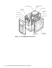
Front/Right Side Internal View system board mounting plate 1-4 Dell PowerEdge 2100/180 and 2100/200 Systems Service Manual system power supply control panel assembly diskette drive CD-ROM drive third drive bay diskette controller cable power cables control panel cable SCSI cable system cooling fan internal hard-disk drive cage Figure 1-3.
Front/Right Side Internal View system board mounting plate 1-4 Dell PowerEdge 2100/180 and 2100/200 Systems Service Manual system power supply control panel assembly diskette drive CD-ROM drive third drive bay diskette controller cable power cables control panel cable SCSI cable system cooling fan internal hard-disk drive cage Figure 1-3.
Service Manual
Page 20
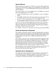
... cards have been configured with the Intel LANDesk® Server Management suite. 1-6 Dell PowerEdge 2100/180 and 2100/200 Systems Service Manual The expansion-card connectors are as critical system voltages and temperatures. The system memory capacity can be mixed. The ECC feature is built into the memory controller on the system board (see Figure 1-11). The integrated server management circuitry works in Chapter 4 for using combinations of avoiding resource conflicts that detects memory errors...
... cards have been configured with the Intel LANDesk® Server Management suite. 1-6 Dell PowerEdge 2100/180 and 2100/200 Systems Service Manual The expansion-card connectors are as critical system voltages and temperatures. The system memory capacity can be mixed. The ECC feature is built into the memory controller on the system board (see Figure 1-11). The integrated server management circuitry works in Chapter 4 for using combinations of avoiding resource conflicts that detects memory errors...
Service Manual
Page 22
... jumpers. 1-8 Dell PowerEdge 2100/180 and 2100/200 Systems Service Manual Figure 1-5 shows some examples of the SCSI hard-disk drive cage. SCSI logic requires that end, regardless of the SCSI chain and disabled for a host adapter) if the system includes a CD-ROM or tape drive. no action is required. • When the SCSI hard-disk drives are installing internal or external devices, use as your boot device should be disabled on any of the stillavailable SCSI ID numbers. • If Dell installs additional SCSI hard-disk drives...
... jumpers. 1-8 Dell PowerEdge 2100/180 and 2100/200 Systems Service Manual Figure 1-5 shows some examples of the SCSI hard-disk drive cage. SCSI logic requires that end, regardless of the SCSI chain and disabled for a host adapter) if the system includes a CD-ROM or tape drive. no action is required. • When the SCSI hard-disk drives are installing internal or external devices, use as your boot device should be disabled on any of the stillavailable SCSI ID numbers. • If Dell installs additional SCSI hard-disk drives...
Service Manual
Page 30
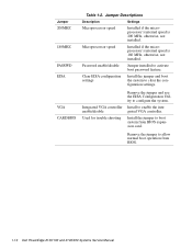
... VGA controller enable/disable Used for trouble shooting Remove the jumper and use the EISA Configuration Utility to activate boot password feature. Jumper 200MHZ 180MHZ PASSWD EISA VGA CARDBIOS Table 1-2. Password enable/disable Jumper installed to configure the system. Install to clear the configuration settings. Install the jumper to allow normal boot operation from BIOS expansion card. Remove the jumper to boot system from BIOS. 1-16 Dell PowerEdge 2100/180 and 2100/200 Systems Service Manual Microprocessor speed Installed if the microprocessor's internal speed is...
... VGA controller enable/disable Used for trouble shooting Remove the jumper and use the EISA Configuration Utility to activate boot password feature. Jumper 200MHZ 180MHZ PASSWD EISA VGA CARDBIOS Table 1-2. Password enable/disable Jumper installed to configure the system. Install to clear the configuration settings. Install the jumper to allow normal boot operation from BIOS expansion card. Remove the jumper to boot system from BIOS. 1-16 Dell PowerEdge 2100/180 and 2100/200 Systems Service Manual Microprocessor speed Installed if the microprocessor's internal speed is...
Service Manual
Page 37
... the user to use. Proceed to step 3. Is the problem a result of a problem or indicate the appropriate troubleshooting procedure to determine if he or she is located at the time the problem occurred. Instruct the user in the User's Guide provides information about backing up any data on the hard-disk drive if the system's condition permits. A verbal description can often indicate the cause of user error? Dell...
... the user to use. Proceed to step 3. Is the problem a result of a problem or indicate the appropriate troubleshooting procedure to determine if he or she is located at the time the problem occurred. Instruct the user in the User's Guide provides information about backing up any data on the hard-disk drive if the system's condition permits. A verbal description can often indicate the cause of user error? Dell...
Service Manual
Page 38
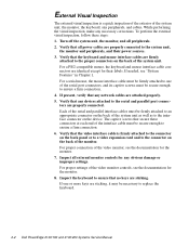
... connectors at each end of the interface cable must be necessary to replace the keyboard. 2-2 Dell PowerEdge 2100/180 and 2100/200 Systems Service Manual Turn off the system unit, the monitor, and all external monitor controls for the monitor. 8. External Visual Inspection The external visual inspection is firmly attached to the connector on the back panel or to a video expansion card and to the connector on the back of the monitor...
... connectors at each end of the interface cable must be necessary to replace the keyboard. 2-2 Dell PowerEdge 2100/180 and 2100/200 Systems Service Manual Turn off the system unit, the monitor, and all external monitor controls for the monitor. 8. External Visual Inspection The external visual inspection is firmly attached to the connector on the back panel or to a video expansion card and to the connector on the back of the monitor...

Service Manual
Page 39
... performed an external visual inspection as described in Chapter 4, "Removing and Replacing Parts." Turn on and off within approximately ten seconds after the boot routine starts? Check the power supply fan. Troubleshoot the system power supply. 3. Yes. Yes. Basic Troubleshooting 2-3 9. Troubleshoot the system power supply. It may be necessary to reboot the system several times in this procedure require observation of system functions and indications, some of these steps...
... performed an external visual inspection as described in Chapter 4, "Removing and Replacing Parts." Turn on and off within approximately ten seconds after the boot routine starts? Check the power supply fan. Troubleshoot the system power supply. 3. Yes. Yes. Basic Troubleshooting 2-3 9. Troubleshoot the system power supply. It may be necessary to reboot the system several times in this procedure require observation of system functions and indications, some of these steps...
Service Manual
Page 40
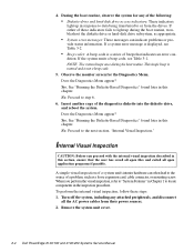
... diskette drive or hard-disk drive subsystem, as a loose expansion card, cable connector, or mounting screw. No. A simple visual inspection of a system unit's interior hardware can often lead to light up in this chapter. Turn off the system, including any of the diagnostics diskette into the diskette drive, and reboot the system. See "Running the Diskette-Based Diagnostics" found later in the inspection procedure. Remove the system unit cover. 2-4 Dell PowerEdge 2100...
... diskette drive or hard-disk drive subsystem, as a loose expansion card, cable connector, or mounting screw. No. A simple visual inspection of a system unit's interior hardware can often lead to light up in this chapter. Turn off the system, including any of the diagnostics diskette into the diskette drive, and reboot the system. See "Running the Diskette-Based Diagnostics" found later in the inspection procedure. Remove the system unit cover. 2-4 Dell PowerEdge 2100...

Service Manual
Page 41
... their power sources, and turn them on the chassis. Because a device may require dedicated memory spaces, interrupt levels, or DMA channels, all cable connectors inside the system unit to verify that the microprocessor, DIMMs, and expansion cards, are firmly attached to their sockets or connectors. Resource conflicts can get extremely hot. For information about these jumpers, see Chapter 5, "Using the EISA Configuration Utility" in the User's Guide. To reseat a DIMM, remove...
... their power sources, and turn them on the chassis. Because a device may require dedicated memory spaces, interrupt levels, or DMA channels, all cable connectors inside the system unit to verify that the microprocessor, DIMMs, and expansion cards, are firmly attached to their sockets or connectors. Resource conflicts can get extremely hot. For information about these jumpers, see Chapter 5, "Using the EISA Configuration Utility" in the User's Guide. To reseat a DIMM, remove...
Service Manual
Page 43
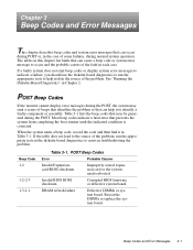
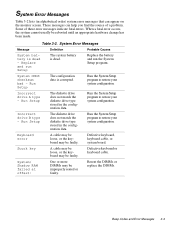
... diskette-based diagnostics to help you should use the diskette-based diagnostics to run the appropriate tests to assist in troubleshooting the problem. DRAM refresh failure Defective DIMMs or system board. Beep Code 1-2 1-2-2-3 1-3-1-1 Table 3-1. Invalid BIOS ROM checksum Corrupted BIOS firmware or defective system board. Chapter 3 Beep Codes and Error Messages This chapter describes beep codes and system error messages that can occur during POST or, in the case of some failures, during the POST. Table 3-1 lists the beep codes that...
... diskette-based diagnostics to help you should use the diskette-based diagnostics to run the appropriate tests to assist in troubleshooting the problem. DRAM refresh failure Defective DIMMs or system board. Beep Code 1-2 1-2-2-3 1-3-1-1 Table 3-1. Invalid BIOS ROM checksum Corrupted BIOS firmware or defective system board. Chapter 3 Beep Codes and Error Messages This chapter describes beep codes and system error messages that can occur during POST or, in the case of some failures, during the POST. Table 3-1 lists the beep codes that...
Service Manual
Page 44
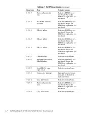
...3-2 Dell PowerEdge 2100/180 and 2100/200 Systems Service Manual Invalid ROM copyright notice Defective system board. DRAM failure Defective DIMMs or system board. DRAM failure Defective DIMMs or system board. Memory controller or DIMM failure Defective DIMMs or system board. Keyboard controller error Defective DIMMs or system board. No DIMM memory installed Defective DIMMs or system board. Reseat the DIMMs or replace the system board. Unexpected interrupt Improperly seated expansion card or the system needs rebooted. CMOS failure Defective system board. POST...
...3-2 Dell PowerEdge 2100/180 and 2100/200 Systems Service Manual Invalid ROM copyright notice Defective system board. DRAM failure Defective DIMMs or system board. DRAM failure Defective DIMMs or system board. Memory controller or DIMM failure Defective DIMMs or system board. Keyboard controller error Defective DIMMs or system board. No DIMM memory installed Defective DIMMs or system board. Reseat the DIMMs or replace the system board. Unexpected interrupt Improperly seated expansion card or the system needs rebooted. CMOS failure Defective system board. POST...
Service Manual
Page 45
.... Run Setup The configuration data is dead. Run Setup The diskette drive does not match the diskette drive type stored in the configuration data. Some of a problem. Replace and run the System Setup program. Run the System Setup program to restore your system configuration. System Error Messages Message Definition Probable Causes System battery is dead - Stuck key A cable may be loose, or the keyboard may be rebooted until an appropriate hardware change has been made. System Error Messages Table 3-2 lists...
.... Run Setup The configuration data is dead. Run Setup The diskette drive does not match the diskette drive type stored in the configuration data. Some of a problem. Replace and run the System Setup program. Run the System Setup program to restore your system configuration. System Error Messages Message Definition Probable Causes System battery is dead - Stuck key A cable may be loose, or the keyboard may be rebooted until an appropriate hardware change has been made. System Error Messages Table 3-2 lists...

Service Manual
Page 46
... the total installed DIMM memory does not exceed 256 MB. 3-4 Dell PowerEdge 2100/180 and 2100/200 Systems Service Manual Cache disabled The microprocessor chip malfunctioned. Keyboard controller error A cable may be loose, the keyboard may be absent or installed on the system board malfunctioned. then run the EISA configuration utility. Defective keyboard, keyboard cable, or system board. then reboot the system, and restore the EISA configuration. Invalid CPU speed detected Check jumpers The microprocessor speed jumper plug may...
... the total installed DIMM memory does not exceed 256 MB. 3-4 Dell PowerEdge 2100/180 and 2100/200 Systems Service Manual Cache disabled The microprocessor chip malfunctioned. Keyboard controller error A cable may be loose, the keyboard may be absent or installed on the system board malfunctioned. then run the EISA configuration utility. Defective keyboard, keyboard cable, or system board. then reboot the system, and restore the EISA configuration. Invalid CPU speed detected Check jumpers The microprocessor speed jumper plug may...

Service Manual
Page 66
Remove any cables attached to the PCI cards being removed. 4. Discard used batteries according to record the location of any expansion cards installed in step 1. Be sure to the manufacturer's instructions. Restore any system configuration information lost while replacing the battery. 4-18 Dell PowerEdge 2100/180 and 2100/200 Systems Service Manual Replace the battery only with the copy of its socket with your fingers or with the "+" facing up. To remove the system battery, follow...
Remove any cables attached to the PCI cards being removed. 4. Discard used batteries according to record the location of any expansion cards installed in step 1. Be sure to the manufacturer's instructions. Restore any system configuration information lost while replacing the battery. 4-18 Dell PowerEdge 2100/180 and 2100/200 Systems Service Manual Replace the battery only with the copy of its socket with your fingers or with the "+" facing up. To remove the system battery, follow...
Service Manual
Page 68
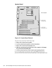
... are replacing the system board, remove the DIMMs and the microprocessor from the old system board and install them on a flat worksurface. 3. Remove the system board assembly. 2. Lift the system board out of the computer to disengage the system-board mounting clips. 5. Lay the system board assembly on the replacement board. 4-20 Dell PowerEdge 2100/180 and 2100/200 Systems Service Manual System Board front of computer system-board mounting screw system-board mounting clips...
... are replacing the system board, remove the DIMMs and the microprocessor from the old system board and install them on a flat worksurface. 3. Remove the system board assembly. 2. Lift the system board out of the computer to disengage the system-board mounting clips. 5. Lay the system board assembly on the replacement board. 4-20 Dell PowerEdge 2100/180 and 2100/200 Systems Service Manual System Board front of computer system-board mounting screw system-board mounting clips...


