

Getting Started Guide
Page 5
...accommodates halflength expansion cards. SMP greatly improves overall system performance by installing combinations of 256-MB, 512-MB, 1-GB or 2-GB memory modules in an expansion-card cage. slot 3 is available on systems with two Intel Xeon processors. System Features The major hardware ...GB by dividing processor operations between independent processors. The upgrade kit from Dell. Slots 1 and 2 are 3.3-V, PCIe x4 lanes. The system board includes the following features: • Six PCI slots located in the eight memory module sockets on the system board. • Support for up ...
...accommodates halflength expansion cards. SMP greatly improves overall system performance by installing combinations of 256-MB, 512-MB, 1-GB or 2-GB memory modules in an expansion-card cage. slot 3 is available on systems with two Intel Xeon processors. System Features The major hardware ...GB by dividing processor operations between independent processors. The upgrade kit from Dell. Slots 1 and 2 are 3.3-V, PCIe x4 lanes. The system board includes the following features: • Six PCI slots located in the eight memory module sockets on the system board. • Support for up ...
Getting Started Guide
Page 6
...optional RAC is installed, the video resolution is 1024 X 768. • Systems management circuitry that monitors operation of DDR SDRAM video memory (nonupgradable). Supported Operating Systems • Microsoft® Windows Server™ 2003 Standard and Enterprise Editions • Microsoft Windows Small Business...and ES (version 3 and version 4) for Intel x86 • Red Hat Enterprise Linux AS and ES (version 4) for Intel Extended Memory 64 Technology (Intel EM64T) • SUSE® Linux Enterprise Server 9 for the latest support information about specific features, see "Technical ...
...optional RAC is installed, the video resolution is 1024 X 768. • Systems management circuitry that monitors operation of DDR SDRAM video memory (nonupgradable). Supported Operating Systems • Microsoft® Windows Server™ 2003 Standard and Enterprise Editions • Microsoft Windows Small Business...and ES (version 3 and version 4) for Intel x86 • Red Hat Enterprise Linux AS and ES (version 4) for Intel Extended Memory 64 Technology (Intel EM64T) • SUSE® Linux Enterprise Server 9 for the latest support information about specific features, see "Technical ...
Getting Started Guide
Page 11
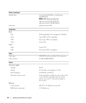
Technical Specifications Processor Processor type Expansion Bus Bus type Expansion slots PCI-X PCIe Memory Architecture Memory module sockets Memory module capacities Minimum RAM Maximum RAM Drives Hard drives Diskette drive One or two Dual-Core Intel Xeon Processors 5000 Sequence PCI, PCI-X, PCIe one ...
Technical Specifications Processor Processor type Expansion Bus Bus type Expansion slots PCI-X PCIe Memory Architecture Memory module sockets Memory module capacities Minimum RAM Maximum RAM Drives Hard drives Diskette drive One or two Dual-Core Intel Xeon Processors 5000 Sequence PCI, PCI-X, PCIe one ...
Getting Started Guide
Page 12
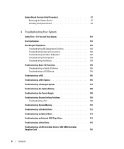
..., USB 2.0-compliant ATI ES1000 video controller; Drives (continued) Optical drive Flash drive Connectors Back NIC Serial USB Video Front Video USB Video Video type Video memory Power AC power supply Wattage Voltage Heat dissipation Maximum inrush current Batteries System battery RAID battery (optional) one optional CD, DVD, or combination CD-RW...
..., USB 2.0-compliant ATI ES1000 video controller; Drives (continued) Optical drive Flash drive Connectors Back NIC Serial USB Video Front Video USB Video Video type Video memory Power AC power supply Wattage Voltage Heat dissipation Maximum inrush current Batteries System battery RAID battery (optional) one optional CD, DVD, or combination CD-RW...

Hardware Owner's Manual (PDF)
Page 5
... Fan Bracket 79 Removing the Back Fan Bracket 80 Replacing the Back Fan Bracket 80 Memory 80 General Memory Module Installation Guidelines 82 Non-Optimal Memory Configurations 82 Memory Sparing Support 82 Memory Mirroring Support 83 Installing Memory Modules 83 Removing Memory Modules 85 Installing a RAC Card 85 Activating the Integrated NIC TOE 87 Microprocessor 87 Replacing...
... Fan Bracket 79 Removing the Back Fan Bracket 80 Replacing the Back Fan Bracket 80 Memory 80 General Memory Module Installation Guidelines 82 Non-Optimal Memory Configurations 82 Memory Sparing Support 82 Memory Mirroring Support 83 Installing Memory Modules 83 Removing Memory Modules 85 Installing a RAC Card 85 Activating the Integrated NIC TOE 87 Microprocessor 87 Replacing...
Hardware Owner's Manual (PDF)
Page 6
... 106 Troubleshooting a Damaged System 107 Troubleshooting the System Battery 108 Troubleshooting the Power Supply 108 Troubleshooting System Cooling Problems 109 Troubleshooting a Fan 109 Troubleshooting System Memory 110 Troubleshooting a Diskette Drive 112 Troubleshooting an Optical Drive 113 Troubleshooting an External SCSI Tape Drive 113 Troubleshooting a Hard Drive 115 Troubleshooting a SAS Controller Card...
... 106 Troubleshooting a Damaged System 107 Troubleshooting the System Battery 108 Troubleshooting the Power Supply 108 Troubleshooting System Cooling Problems 109 Troubleshooting a Fan 109 Troubleshooting System Memory 110 Troubleshooting a Diskette Drive 112 Troubleshooting an Optical Drive 113 Troubleshooting an External SCSI Tape Drive 113 Troubleshooting a Hard Drive 115 Troubleshooting a SAS Controller Card...
Hardware Owner's Manual (PDF)
Page 16
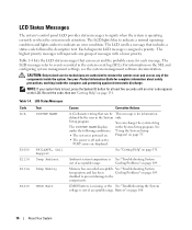
... in the System Setup program. LCD Status Messages Code Text N/A SYSTEM NAME E1000 E1114 FAILSAFE, Call Support Temp Ambient E1116 Temp Memory E1210 CMOS Batt Causes Corrective Actions A 62-character string that includes a status code followed by the user in the system event ...displayed. Table 1-4. Ambient system temperature is for at least five seconds until an error code appears on page 131. Setup program. Memory has exceeded acceptable See "Troubleshooting System temperature and has been Cooling Problems" on page 108. 16 About Your System Battery" on page...
... in the System Setup program. LCD Status Messages Code Text N/A SYSTEM NAME E1000 E1114 FAILSAFE, Call Support Temp Ambient E1116 Temp Memory E1210 CMOS Batt Causes Corrective Actions A 62-character string that includes a status code followed by the user in the system event ...displayed. Table 1-4. Ambient system temperature is for at least five seconds until an error code appears on page 131. Setup program. Memory has exceeded acceptable See "Troubleshooting System temperature and has been Cooling Problems" on page 108. 16 About Your System Battery" on page...

Hardware Owner's Manual (PDF)
Page 20
... refresh failure. Kybd Controller Keyboard controller failure. See "Getting Help" on page 110. POST Mem Test BIOS POST memory test failure. See "Troubleshooting System Memory" on page 131. Shadow BIOS Fail The system BIOS failed to the latest BMC firmware. See "Getting Help" ... See "Getting Help" on setup and use of BMC. Prog Timer Programmable interval timer error. SIO Err SIO failure. Unusable Memory Memory is not configurable. Memory" on page 131. See "Getting Help" on page 110. SMI Init System management interrupt See "Getting Help" on page...
... refresh failure. Kybd Controller Keyboard controller failure. See "Getting Help" on page 110. POST Mem Test BIOS POST memory test failure. See "Troubleshooting System Memory" on page 131. Shadow BIOS Fail The system BIOS failed to the latest BMC firmware. See "Getting Help" ... See "Getting Help" on setup and use of BMC. Prog Timer Programmable interval timer error. SIO Err SIO failure. Unusable Memory Memory is not configurable. Memory" on page 131. See "Getting Help" on page 110. SMI Init System management interrupt See "Getting Help" on page...

Hardware Owner's Manual (PDF)
Page 21
... E2111 E2112 E2113 Text Causes Corrective Actions DRAC Config Dell remote access controller Check screen for specific error messages. Check screen for specific error (DRAC) configuration failure. System Memory" on page 110. "##" represents the DIMM implicated by... represents the DIMM pair implicated by "## & ##" has had too many errors. messages. Memory Population Incorrect memory configuration. Check screen for specific error Memory population order messages. About Your System 21 Check screen for specific error messages. POST Fail General...
... E2111 E2112 E2113 Text Causes Corrective Actions DRAC Config Dell remote access controller Check screen for specific error messages. Check screen for specific error (DRAC) configuration failure. System Memory" on page 110. "##" represents the DIMM implicated by... represents the DIMM pair implicated by "## & ##" has had too many errors. messages. Memory Population Incorrect memory configuration. Check screen for specific error Memory population order messages. About Your System 21 Check screen for specific error messages. POST Fail General...
Hardware Owner's Manual (PDF)
Page 22
...For example, if the code E0780 MISSING CPU 1 appears, you know that is not installed in the See "Troubleshooting System FBD memory subsystem link on Memory" on the Northbound side has failed. LCD Status Messages (continued) Code Text Causes Corrective Actions E2118 Fatal NB Mem CRC One... of an abbreviation or acronym used in the Fully Buffered DIMM (FBD) memory subsystem link on page 110. messages can often specify a very precise fault condition that a microprocessor is easily corrected. NOTE: For the ...
...For example, if the code E0780 MISSING CPU 1 appears, you know that is not installed in the See "Troubleshooting System FBD memory subsystem link on Memory" on the Northbound side has failed. LCD Status Messages (continued) Code Text Causes Corrective Actions E2118 Fatal NB Mem CRC One... of an abbreviation or acronym used in the Fully Buffered DIMM (FBD) memory subsystem link on page 110. messages can often specify a very precise fault condition that a microprocessor is easily corrected. NOTE: For the ...
Hardware Owner's Manual (PDF)
Page 23
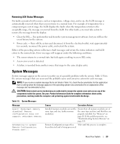
...1-5, check the documentation for the application that maps to the same display entry. If the problem persists, see "Troubleshooting System Memory" on page 80. About Your System 23 For example, if temperature for an explanation of the message and recommended action. when...has Wait until the process is being processed. Removing LCD Status Messages For faults associated with the system. Please wait... Redundant memory disabled! See "Memory" on page 110. Either of the preceding actions will reappear under the following conditions: • The sensor returns to a...
...1-5, check the documentation for the application that maps to the same display entry. If the problem persists, see "Troubleshooting System Memory" on page 80. About Your System 23 For example, if temperature for an explanation of the message and recommended action. when...has Wait until the process is being processed. Removing LCD Status Messages For faults associated with the system. Please wait... Redundant memory disabled! See "Memory" on page 110. Either of the preceding actions will reappear under the following conditions: • The sensor returns to a...
Hardware Owner's Manual (PDF)
Page 24
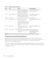
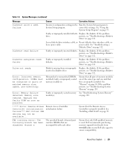
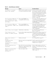
..., speed, and technology. beginning with a single-rank DIMM. Only memory installed in pairs. Memory" on page 110. is installed on page 131. Decreasing available memory Faulty or improperly installed memory See "Troubleshooting System Memory" modules. The following DIMM is mismatched: DIMM x and DIMM ...The following DIMM/rank has been disabled by BIOS: DIMM x Rank y Mismatched DIMMs installed; Ensure that all pairs of memory modules are of the same type and size and that they are properly installed. System Messages (continued) Message Causes Corrective Actions...
..., speed, and technology. beginning with a single-rank DIMM. Only memory installed in pairs. Memory" on page 110. is installed on page 131. Decreasing available memory Faulty or improperly installed memory See "Troubleshooting System Memory" modules. The following DIMM is mismatched: DIMM x and DIMM ...The following DIMM/rank has been disabled by BIOS: DIMM x Rank y Mismatched DIMMs installed; Ensure that all pairs of memory modules are of the same type and size and that they are properly installed. System Messages (continued) Message Causes Corrective Actions...
Hardware Owner's Manual (PDF)
Page 25
... page 33. About Your System 25 See "Troubleshooting a Diskette Drive" on page 85. Replace the diskette. Error: Incorrect memory configuration. faulty or improperly seated memory module(s). Error: Memory failure detected. on page 112. Dell recommends purchasing memory upgrade kits directly from or improperly inserted in the Run the System Setup program to ensure compatibility. If...
... page 33. About Your System 25 See "Troubleshooting a Diskette Drive" on page 85. Replace the diskette. Error: Incorrect memory configuration. faulty or improperly seated memory module(s). Error: Memory failure detected. on page 112. Dell recommends purchasing memory upgrade kits directly from or improperly inserted in the Run the System Setup program to ensure compatibility. If...
Hardware Owner's Manual (PDF)
Page 26
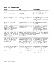
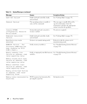
...26 About Your System No action is in manufacturing mode. See "Getting Help" on page 110. Faulty or improperly installed memory See "Troubleshooting System Memory" modules. pressing the spacebar. Table 1-5. System Messages (continued) Message Gate A20 failure General failure Invalid NVRAM configuration, ...Resource Re-allocated Keyboard Controller failure Manufacturing mode detected MEMBIST failure - See "Troubleshooting System Memory" on page 131. faulty system board. This message is unable to resolve the problem. faulty system board System is required....
...26 About Your System No action is in manufacturing mode. See "Getting Help" on page 110. Faulty or improperly installed memory See "Troubleshooting System Memory" modules. pressing the spacebar. Table 1-5. System Messages (continued) Message Gate A20 failure General failure Invalid NVRAM configuration, ...Resource Re-allocated Keyboard Controller failure Manufacturing mode detected MEMBIST failure - See "Troubleshooting System Memory" on page 131. faulty system board. This message is unable to resolve the problem. faulty system board System is required....
Hardware Owner's Manual (PDF)
Page 27
... System Setup program, or no boot disk in the specified slot. The specified DIMM was unable to establish a successful data link with the memory controller. See "Troubleshooting System Memory" on hard drive. Faulty or improperly installed PCIe card in the specified slot number. If the problem persists, see "Getting Help" on page...
... System Setup program, or no boot disk in the specified slot. The specified DIMM was unable to establish a successful data link with the memory controller. See "Troubleshooting System Memory" on hard drive. Faulty or improperly installed PCIe card in the specified slot number. If the problem persists, see "Getting Help" on page...
Hardware Owner's Manual (PDF)
Page 28
... Your System See "Troubleshooting a Diskette Drive" on page 112 or "Troubleshooting a Hard Drive" on page 117. Ensure that faulty. If the card(s); See "Troubleshooting System Memory" on page 117. Ensure that checksum failure is defective. Read fault The operating system cannot read Requested sector not found Seek error Seek operation failed...
... Your System See "Troubleshooting a Diskette Drive" on page 112 or "Troubleshooting a Hard Drive" on page 117. Ensure that faulty. If the card(s); See "Troubleshooting System Memory" on page 117. Ensure that checksum failure is defective. Read fault The operating system cannot read Requested sector not found Seek error Seek operation failed...
Hardware Owner's Manual (PDF)
Page 29
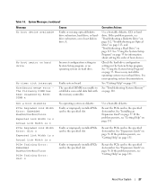
...removed, this message is informative and can be faulty. If memory has not been added or removed, check the SEL to ensure compatibility. Dell recommends purchasing memory upgrade kits directly from www.dell.com or your Dell sales agent to ensure compatibility. See "Troubleshooting the System Battery... Microprocessor(s) is used . Create a utility partition on page 75. Warning! About Your System 29 Dell recommends purchasing memory upgrade kits directly from www.dell.com or your Dell sales agent to determine if single-bit or multi-bit errors were detected and replace the faulty...
...removed, this message is informative and can be faulty. If memory has not been added or removed, check the SEL to ensure compatibility. Dell recommends purchasing memory upgrade kits directly from www.dell.com or your Dell sales agent to ensure compatibility. See "Troubleshooting the System Battery... Microprocessor(s) is used . Create a utility partition on page 75. Warning! About Your System 29 Dell recommends purchasing memory upgrade kits directly from www.dell.com or your Dell sales agent to determine if single-bit or multi-bit errors were detected and replace the faulty...
Hardware Owner's Manual (PDF)
Page 30
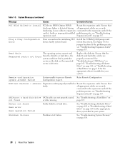
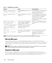
...System Messages (continued) Message Causes Corrective Actions Warning: Embedded RAID firmware is not optimal. Embedded RAID firmware responds with slot 1. Dell recommends a population of DIMMs (for information about installing or updating the RAID firmware. For example, before the system continues a task...2, 4, or 8 DIMMs sequentially beginning with an error. For more information, see the "Glossary" on the diskette. See "Memory" on selected drive Faulty diskette, optical/diskette drive assembly, hard drive, or hard-drive subsystem. Warning Messages A warning message ...
...System Messages (continued) Message Causes Corrective Actions Warning: Embedded RAID firmware is not optimal. Embedded RAID firmware responds with slot 1. Dell recommends a population of DIMMs (for information about installing or updating the RAID firmware. For example, before the system continues a task...2, 4, or 8 DIMMs sequentially beginning with an error. For more information, see the "Glossary" on the diskette. See "Memory" on selected drive Faulty diskette, optical/diskette drive assembly, hard drive, or hard-drive subsystem. Warning Messages A warning message ...
Hardware Owner's Manual (PDF)
Page 33
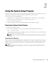
... program by responding to load before you see the following message display briefly on page 23 for an explanation of the message. NOTE: After installing a memory upgrade, it is booting, make a note of the message and suggestions for example, the time or date • Enable or disable integrated devices • Correct...
... program by responding to load before you see the following message display briefly on page 23 for an explanation of the message. NOTE: After installing a memory upgrade, it is booting, make a note of the message and suggestions for example, the time or date • Enable or disable integrated devices • Correct...
Hardware Owner's Manual (PDF)
Page 36
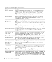
...each of keyboard errors during POST. NOTE: The Snoop Filter option may optimize or degrade the performance of memory modules, system video memory size, system memory test option, and redundant memory status, and snoop filter. PCI IRQ Assignment Displays a screen to change the IRQ assigned to installed system...Displays information related to set a userdefined LCD string. NOTE: System boot is attached to a SAS or SCSI adapter. See support.dell.com for boot devices during system startup. Hard-Disk Drive Sequence Specifies the order in which the system searches for the latest support ...
...each of keyboard errors during POST. NOTE: The Snoop Filter option may optimize or degrade the performance of memory modules, system video memory size, system memory test option, and redundant memory status, and snoop filter. PCI IRQ Assignment Displays a screen to change the IRQ assigned to installed system...Displays information related to set a userdefined LCD string. NOTE: System boot is attached to a SAS or SCSI adapter. See support.dell.com for boot devices during system startup. Hard-Disk Drive Sequence Specifies the order in which the system searches for the latest support ...


