Microprocessor Upgrade Installation Guide
Page 3
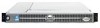
...System Information document. 1 Turn off the system, including any peripherals, and disconnect the power cable from the electrical outlet. 2 Open the system doors, or remove the system cover (see your system. In addition to accommodate secondary microprocessors. Each microprocessor and its... In a single microprocessor system, the microprocessor must be present to the ZIF socket for the primary microprocessor on the Dell Support website at support.dell.com, and upgrade the BIOS if necessary. CAUTION: See "Protecting Against Electrostatic Discharge" in the safety instructions in ...
...System Information document. 1 Turn off the system, including any peripherals, and disconnect the power cable from the electrical outlet. 2 Open the system doors, or remove the system cover (see your system. In addition to accommodate secondary microprocessors. Each microprocessor and its... In a single microprocessor system, the microprocessor must be present to the ZIF socket for the primary microprocessor on the Dell Support website at support.dell.com, and upgrade the BIOS if necessary. CAUTION: See "Protecting Against Electrostatic Discharge" in the safety instructions in ...
Microprocessor Upgrade Installation Guide
Page 4
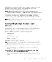
www.dell.com | support.dell.com 4 If you can remove the fan to provide easier access to the heat-sink...damage the microprocessor. 6 Lift the microprocessor out of the pins on removing a cooling fan, see "Getting Help" in the open position (see Figure 1-1). The heat sink is mounted on a flat surface to prevent the thermal interface material from the heat sink.... If any of the pins when unpacking the microprocessor. NOTE: If a cooling fan is necessary to the fully open position so that the socket is ready for information on the retention clip tab, and then removing the clip from ...
www.dell.com | support.dell.com 4 If you can remove the fan to provide easier access to the heat-sink...damage the microprocessor. 6 Lift the microprocessor out of the pins on removing a cooling fan, see "Getting Help" in the open position (see Figure 1-1). The heat sink is mounted on a flat surface to prevent the thermal interface material from the heat sink.... If any of the pins when unpacking the microprocessor. NOTE: If a cooling fan is necessary to the fully open position so that the socket is ready for information on the retention clip tab, and then removing the clip from ...
Microprocessor Upgrade Installation Guide
Page 5
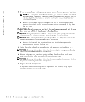
... socket, rotate the socket release lever back down into the socket with pin 1 on the microprocessor go into place, locking the microprocessor in the fully open position. b Align pin 1 on the system. Because the system uses a ZIF microprocessor socket, there is no need to bend the pins. 8 Install the microprocessor in...
... socket, rotate the socket release lever back down into the socket with pin 1 on the microprocessor go into place, locking the microprocessor in the fully open position. b Align pin 1 on the system. Because the system uses a ZIF microprocessor socket, there is no need to bend the pins. 8 Install the microprocessor in...

Information Update (.pdf)
Page 6
... the board out of the chassis. See Figure 1-2. 1-2 Installing or Replacing an ERA/O Card www.dell.com | support.dell.com Figure 1-1. b Disconnect the diskette-drive interface cable from the CD_ROM connector on the backplane board. See Figure 1-2. Opening the System Covers left cover optional security screw latch right cover 6 Remove the SCSI backplane...
... the board out of the chassis. See Figure 1-2. 1-2 Installing or Replacing an ERA/O Card www.dell.com | support.dell.com Figure 1-1. b Disconnect the diskette-drive interface cable from the CD_ROM connector on the backplane board. See Figure 1-2. Opening the System Covers left cover optional security screw latch right cover 6 Remove the SCSI backplane...

Information Update (.pdf)
Page 11
.../O card connector while lifting that end of the components inside the computer, and protecting against electrostatic discharge. 1 Perform steps 1-7 in "Installing an ERA/O Card." 2 Push open the remaining two retention clips and remove the card completely. 4 Perform steps 10-15 in "Installing an ERA/O Card." 5 Disconnect the network cable from the...
.../O card connector while lifting that end of the components inside the computer, and protecting against electrostatic discharge. 1 Perform steps 1-7 in "Installing an ERA/O Card." 2 Push open the remaining two retention clips and remove the card completely. 4 Perform steps 10-15 in "Installing an ERA/O Card." 5 Disconnect the network cable from the...

Installation and Troubleshooting Guide (.htm)
Page 6
.... . . Figure 1-3. Figure 1-4. Figure 1-15. Figure 1-6. Figure 1-13. Figure 1-9. Routing Cables Two-Post Rack Kit Components Two-Post, Open-Frame Relay Rack Universal-Hole Spacing Two-Post, Open-Frame Relay Rack Wide-Hole Spacing Installing the Slide Assemblies for Flush-Mount Configuration 1-4 1-5 1-6 1-7 1-8 1-9 1-11 1-12 1-13 1-14 ... . . Figure 1-17. Figure 1-14. Index Figures Figure 1-1. Figure 1-2. Figure 1-11. Figure 1-12. Installing the VersaRails Slide Assemblies . . . Opening the Wire Covers Installing the Power Cord Strain Relief . . .
.... . . Figure 1-3. Figure 1-4. Figure 1-15. Figure 1-6. Figure 1-13. Figure 1-9. Routing Cables Two-Post Rack Kit Components Two-Post, Open-Frame Relay Rack Universal-Hole Spacing Two-Post, Open-Frame Relay Rack Wide-Hole Spacing Installing the Slide Assemblies for Flush-Mount Configuration 1-4 1-5 1-6 1-7 1-8 1-9 1-11 1-12 1-13 1-14 ... . . Figure 1-17. Figure 1-14. Index Figures Figure 1-1. Figure 1-2. Figure 1-11. Figure 1-12. Installing the VersaRails Slide Assemblies . . . Opening the Wire Covers Installing the Power Cord Strain Relief . . .

Installation and Troubleshooting Guide (.htm)
Page 8
...component is required for trained service technicians installing one or more information on the front and back panels to be installed in an open-frame relay rack. CAUTION: Do not install rack kit components designed for another system may result in damage to the system and...these indicators, see the User's Guide. Use only the rack kit for installing both RapidRails and VersaRails rack kits are similar. www.dell.com | support.dell.com CAUTION: Safety Instructions (continued) • Use caution when pressing the component rail release latches and sliding a component into the ...
...component is required for trained service technicians installing one or more information on the front and back panels to be installed in an open-frame relay rack. CAUTION: Do not install rack kit components designed for another system may result in damage to the system and...these indicators, see the User's Guide. Use only the rack kit for installing both RapidRails and VersaRails rack kits are similar. www.dell.com | support.dell.com CAUTION: Safety Instructions (continued) • Use caution when pressing the component rail release latches and sliding a component into the ...

Installation and Troubleshooting Guide (.htm)
Page 19
... part of the arm. The stop block prevents the cable-management arm from moving backward and supports the weight of the arm with its connector. 6 Open the wire covers on the cable-management arm by lifting the center of the wire over the top of the embossed round button on the... kit has two stop block. 5 Install the status-indicator cable plug into its load of the opposite slide assembly (see Figure 1-8). The wire cover swings open position status indicator Rack Installation Guide 1-13 You can only install the proper stop blocks: one for right-side mounting and one for left-side...
... part of the arm. The stop block prevents the cable-management arm from moving backward and supports the weight of the arm with its connector. 6 Open the wire covers on the cable-management arm by lifting the center of the wire over the top of the embossed round button on the... kit has two stop block. 5 Install the status-indicator cable plug into its load of the opposite slide assembly (see Figure 1-8). The wire cover swings open position status indicator Rack Installation Guide 1-13 You can only install the proper stop blocks: one for right-side mounting and one for left-side...

Installation and Troubleshooting Guide (.htm)
Page 22
...industry standards. CAUTION: Because of the size and weight of the rack cabinet doors, never attempt to install the system into a two-post, open -frame relay rack, such as those found in telecommunications equipment facilities. Damage to the system and personal injury to yourself and to install a... driver (if changing bracket to flush-mount configuration) • Masking tape or felt-tip pen to the procedures for servicing. www.dell.com | support.dell.com Replacing the Rack Doors Refer to mark the mounting holes 1-16 Rack Installation Guide Both 3-inch and 6-inch wide twopost racks ...
...industry standards. CAUTION: Because of the size and weight of the rack cabinet doors, never attempt to install the system into a two-post, open -frame relay rack, such as those found in telecommunications equipment facilities. Damage to the system and personal injury to yourself and to install a... driver (if changing bracket to flush-mount configuration) • Masking tape or felt-tip pen to the procedures for servicing. www.dell.com | support.dell.com Replacing the Rack Doors Refer to mark the mounting holes 1-16 Rack Installation Guide Both 3-inch and 6-inch wide twopost racks ...

Installation and Troubleshooting Guide (.htm)
Page 24
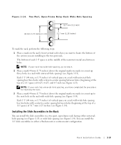
Figure 1-13. www.dell.com | support.dell.com 4 Installing the cable-management arm 5 Routing cables Marking the Rack You must allow 1 U (44 mm or 1.75 inches) of holes (see Figure 1-14). 1-18 ... hole of a 1-U space) of 31.7 mm and 12.7 mm (1.25 inches and 0.5 inch) for each system you install in the two-post rack. Two-Post, Open-Frame Relay Rack Universal-Hole Spacing 44 mm (1.75 inches [1 U]) 12.7 mm (0.5 inch) 15.9 mm (0.625 inch) 15.9 mm (0.625 inch) Wide-Hole Spacing Racks...
Figure 1-13. www.dell.com | support.dell.com 4 Installing the cable-management arm 5 Routing cables Marking the Rack You must allow 1 U (44 mm or 1.75 inches) of holes (see Figure 1-14). 1-18 ... hole of a 1-U space) of 31.7 mm and 12.7 mm (1.25 inches and 0.5 inch) for each system you install in the two-post rack. Two-Post, Open-Frame Relay Rack Universal-Hole Spacing 44 mm (1.75 inches [1 U]) 12.7 mm (0.5 inch) 15.9 mm (0.625 inch) 15.9 mm (0.625 inch) Wide-Hole Spacing Racks...
Installation and Troubleshooting Guide (.htm)
Page 25
...625, and 0.5 inch (see Figure 1-13). Installing the Slide Assemblies in the Rack You can install the 1-U slide assemblies in a two-post, open-frame rack having either a flush-mount or center-mount configuration. NOTE: If your rack has universal-hole spacing, you have completed the procedure for marking...75 inches) above the original mark you are installing in a rack with wide-hole spacing (see Figure 1-13). Rack Installation Guide 1-19 Two-Post, Open-Frame Relay Rack Wide-Hole Spacing 12.7 mm (0.5 inch) 44 mm (1.75 inches [1 U]) 31.7 mm (1.25 inches) To mark the rack, perform...
...625, and 0.5 inch (see Figure 1-13). Installing the Slide Assemblies in the Rack You can install the 1-U slide assemblies in a two-post, open-frame rack having either a flush-mount or center-mount configuration. NOTE: If your rack has universal-hole spacing, you have completed the procedure for marking...75 inches) above the original mark you are installing in a rack with wide-hole spacing (see Figure 1-13). Rack Installation Guide 1-19 Two-Post, Open-Frame Relay Rack Wide-Hole Spacing 12.7 mm (0.5 inch) 44 mm (1.75 inches [1 U]) 31.7 mm (1.25 inches) To mark the rack, perform...

Installation and Troubleshooting Guide (.htm)
Page 27
Installing the Slide Assemblies for Center-Mount Configuration two-post open-frame rack 12-24 x 0.5-inch panhead Phillips screws (4 per slide assembly) slide assembly slide release latch Rack Installation Guide 1-21 Figure 1-15.
Installing the Slide Assemblies for Center-Mount Configuration two-post open-frame rack 12-24 x 0.5-inch panhead Phillips screws (4 per slide assembly) slide assembly slide release latch Rack Installation Guide 1-21 Figure 1-15.

Installation and Troubleshooting Guide (.htm)
Page 30
Installing the Slide Assemblies for Flush-Mount Configuration two-post open-frame rack joined bracket 12-24 x 0.5-inch panhead Phillips screw (4 each slide) shoulder screw on system system release latch slide assembly slide release latch 9 Secure ... right slide assembly in the rack at the location you tightened with two 12-24 x 0.5-inch Phillips screws (see Figure 1-18). Figure 1-18. www.dell.com | support.dell.com 8 Holding the left slide assembly into position in the rack. 11 Use an 11/32-inch wrench or nut driver to fully tighten...
Installing the Slide Assemblies for Flush-Mount Configuration two-post open-frame rack joined bracket 12-24 x 0.5-inch panhead Phillips screw (4 each slide) shoulder screw on system system release latch slide assembly slide release latch 9 Secure ... right slide assembly in the rack at the location you tightened with two 12-24 x 0.5-inch Phillips screws (see Figure 1-18). Figure 1-18. www.dell.com | support.dell.com 8 Holding the left slide assembly into position in the rack. 11 Use an 11/32-inch wrench or nut driver to fully tighten...


