Dell PowerEdge 1750 Support Question
Dell PowerEdge 1750 Support Question
Find answers below for this question about Dell PowerEdge 1750.Need a Dell PowerEdge 1750 manual? We have 3 online manuals for this item!
Question posted by Thxfil on June 5th, 2014
How To Open Dell Poweredge 1750
The person who posted this question about this Dell product did not include a detailed explanation. Please use the "Request More Information" button to the right if more details would help you to answer this question.
Current Answers
Related Dell PowerEdge 1750 Manual Pages
Microprocessor
Upgrade Installation Guide - Page 2

...Trademarks used in this document is subject to change without the written permission of Dell Computer Corporation.
A05
March 2003
P/N 9D904 Rev. NOTICE: A NOTICE indicates either...claiming the marks and names or their products.
Information in this text: Dell and the DELL logo are trademarks of Dell Computer Corporation is strictly forbidden. Notes, Notices, and Cautions
NOTE: A...
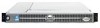
Microprocessor
Upgrade Installation Guide - Page 3
...off the system, including any peripherals, and disconnect the power cable from the electrical outlet.
2 Open the system doors, or remove the system cover (see your system.
Adding or Replacing a ...microprocessors. In addition to the ZIF socket for the primary microprocessor on the Dell Support website at support.dell.com, and upgrade the BIOS if necessary. The following subsection describes how...
Microprocessor
Upgrade Installation Guide - Page 4
... the heat sink.
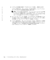
5 Swing the socket release lever upward to the fully open position so that the socket is necessary to maintain proper thermal conditions. The heat... sink.
See your Installation and Troubleshooting Guide.
1-2
Microprocessor Upgrade Installation Guide
www.dell.com | support.dell.com
4 If you intend to remove the microprocessor.
CAUTION: The microprocessor and ...
Microprocessor
Upgrade Installation Guide - Page 5
... to bend the pins.
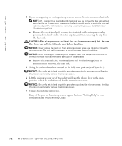
8 Install the microprocessor in the socket (see Figure 1-1).
a Ensure that all pins are matched with the correct holes in the fully open position. When placing the microprocessor in the ZIF socket, be sure that the microprocessor socket release lever is fully seated in the socket, rotate the...
Microprocessor
Upgrade Installation Guide - Page 6
... heat-sink thermal grease is provided, clean the heat sink and apply the thermal grease before placing the heat sink on the microprocessor.
www.dell.com | support.dell.com
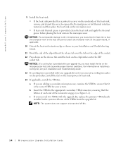
9 Install the heat sink.
• If the heat sink provided has a protective cover on the underside of the heat sink, remove and discard...
Microprocessor
Upgrade Installation Guide - Page 34
www.dell.com | support.dell.com
2 Installation and Troubleshooting Guide
3 Installation and Troubleshooting Guide
4
Installation and Troubleshooting Guide
a
b Installation and Troubleshooting Guide
5 5-1
6
5-2
Microprocessor
Upgrade Installation Guide - Page 36
www.dell.com | support.dell.com
c 1
ZIF
d
9
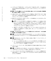
10 『Installation and Troubleshooting Guide
11
12 ZIF
Installation and Troubleshooting Guide
13
5-4
Microprocessor
Upgrade Installation Guide - Page 38
www.dell.com | support.dell.com
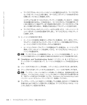
17
NVRAM RAM
18
19 Installation and Troubleshooting Guide
5-6
Information Update (.pdf) - Page 4

..., personal injury, or death.
NOTICE: A NOTICE indicates either the entities claiming the marks and names or their products.
Reproduction in this text: Dell, PowerEdge, and the DELL logo are trademarks of Dell Computer Corporation is subject to either potential damage to hardware or loss of your computer.
Notes, Notices, and Cautions
NOTE: A NOTE indicates...
Information Update (.pdf) - Page 5

...system's Embedded Remote Access Option (ERA/O) card.
See your System Information Guide for PowerEdge™ systems. Collectively, these solutions are authorized to provide remote management capabilities for...an ERA/O Card
1-1
See Figure 1-1.
4 Press the latch on the Dell Support website at support.dell.com. Before installing the ERA/O card, record the system configuration settings. ...
Information Update (.pdf) - Page 6

...diskette-drive interface cable from the CD_ROM connector on the backplane board. Opening the System Covers left cover
optional security screw latch
right cover
6 ... the backplane board. See Figure 1-2. See Figure 1-2.
1-2
Installing or Replacing an ERA/O Card
www.dell.com | support.dell.com
Figure 1-1.
d Press the release latch in toward the backplane board and use the handle to...
Information Update (.pdf) - Page 8

... the connector on the bottom of the ERA/O card with the center posts of the card with the ERA/O connector on the system board; www.dell.com | support.dell.com
Figure 1-3.
Information Update (.pdf) - Page 10
www.dell.com | support.dell.com
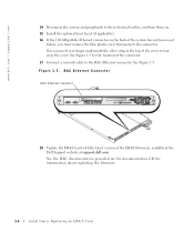
14 Reconnect the system and peripherals to tear away the cover.
Figure 1-5. RAC Ethernet Connector
RAC... protects the connector. See the RAC documentation provided on the back of the ERA/O firmware, available at the Dell Support website at support.dell.com. You can insert your finger underneath the silver strip at the top of the cover to their electrical ...
Information Update (.pdf) - Page 11

...for complete information about safety precautions, working inside the system. See Figure 1-4.
3 Push open the two retention clips nearest the ERA/O card connector while lifting that end of the ...and protecting against electrostatic discharge.
1 Perform steps 1-7 in "Installing an ERA/O Card."
2 Push open the remaining two retention clips and remove the card completely.
4 Perform steps 10-15 in "...
Installation and
Troubleshooting Guide (.htm) - Page 4

... may be used in this document to refer to either potential damage to hardware or loss of data and tells you make better use of Dell Computer Corporation. Trademarks used in trademarks and trade names other than its own. Notes, Notices, and Cautions
NOTE: A NOTE indicates important information that helps you...
Installation and
Troubleshooting Guide (.htm) - Page 6

... Assemblies for Flush-Mount Configuration
1-4 1-5 1-6 1-7 1-8 1-9
1-11 1-12 1-13 1-14 1-15 1-17
1-18
1-19
1-21
1-22
1-23
1-24
4
Contents Figure 1-3. Figure 1-4. Figure 1-13.
Figure 1-17. Opening the Wire Covers Installing the Power Cord Strain Relief . . . Figure 1-2. Figure 1-6. Figure 1-9.
Figure 1-18. Figure 1-8. Routing Cables Two-Post Rack Kit Components Two-Post...
Installation and
Troubleshooting Guide (.htm) - Page 8

... installing one or more information on any component when servicing other components in an open-frame relay rack. Before attempting this installation, you should not exceed 80 percent of... system and personal injury to yourself and to others.
1-2
Rack Installation Guide www.dell.com | support.dell.com
CAUTION: Safety Instructions (continued)
• Use caution when pressing the component...
Installation and
Troubleshooting Guide (.htm) - Page 22

... or a flush-mount configuration.
See the two-post, open -frame relay rack that has not been securely anchored in place. www.dell.com | support.dell.com
Replacing the Rack Doors
Refer to the procedures for ...and Supplies
You need the following tools and supplies to install the system in a two-post, open frame relay rack to the floor, the ceiling or upper wall, and where applicable, to adjacent...
Installation and
Troubleshooting Guide (.htm) - Page 24

Two-Post, Open-Frame Relay Rack Universal-Hole Spacing
44 mm (1.75 inches [1 U])
12.7 mm (0.5 inch) 15.9 mm (0.625 inch)...vertical column of vertical space for the front and back vertical column of holes (see Figure 1-14).
1-18
Rack Installation Guide www.dell.com | support.dell.com
4 Installing the cable-management arm 5 Routing cables
Marking the Rack
You must allow 1 U (44 mm or 1.75 ...
Installation and
Troubleshooting Guide (.htm) - Page 30

Installing the Slide Assemblies for Flush-Mount Configuration
two-post open-frame rack
joined bracket
12-24 x 0.5-inch panhead Phillips screw (4 each slide)
shoulder screw ...post rail with two 12-24 x 0.5-inch pan-head Phillips screws (see Figure 1-18).
Figure 1-18. www.dell.com | support.dell.com
8 Holding the left slide assembly into position in the rack.
11 Use an 11/32-inch wrench or ...
Similar Questions


Raid Setup
Looking for instructions on setting up raid 5 on a poweredge 1750, and creating spare drives.
Looking for instructions on setting up raid 5 on a poweredge 1750, and creating spare drives.
(Posted by ffisher 12 years ago)