Dell PowerEdge R210 Support Question
Dell PowerEdge R210 Support Question
Find answers below for this question about Dell PowerEdge R210.Need a Dell PowerEdge R210 manual? We have 6 online manuals for this item!
Question posted by dmbSp on June 7th, 2014
How To Open Poweredge R210 Case
The person who posted this question about this Dell product did not include a detailed explanation. Please use the "Request More Information" button to the right if more details would help you to answer this question.
Current Answers
Related Dell PowerEdge R210 Manual Pages
Getting Started Guide - Page 3

Dell™ PowerEdge™ R210 Systems
Getting Started With Your System
Regulatory Model E10S Regulatory Type E10S001
www.dell.com | support.dell.com
Getting Started Guide - Page 4

...instructions are trademarks of these materials in this text: Dell, the DELL logo, and PowerEdge are not followed. Trademarks used in any proprietary interest in the United States and other ... claiming the marks and names or their products.
Microsoft, Hyper-V, Windows, and Windows Server are registered trademarks of Intel Corporation in the United States and other than its own....
Hardware Owner's Manual - Page 2

Microsoft, Windows, Windows Server, and MS-DOS are either the entities claiming the marks and names or their products.
... trademarks or registered trademarks of Microsoft Corporation in any proprietary interest in this text: Dell, the DELL logo, and PowerEdge are not followed. Dell Inc. Information in trademarks and trade names other countries.
is subject to hardware or loss...
Hardware Owner's Manual - Page 5
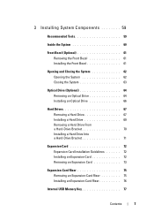
... Components 59
Recommended Tools 59
Inside the System 60
Front Bezel (Optional 61 Removing the Front Bezel 61 Installing the Front Bezel 61
Opening and Closing the System 62 Opening the System 62 Closing the System 63
Optical Drive (Optional 64 Removing an Optical Drive 64 Installing an Optical Drive 66
Hard...
Hardware Owner's Manual - Page 11

... for PXE boot. About Your System
13 For more information, see the Unified Server Configurator documentation. See "Using the System Setup Program and UEFI Boot Manager" on.... Enters the Baseboard Management Controller (BMC) or iDRAC Configuration Utility, which opens the Unified Server Configurator (USC).
For more information, see your integrated NIC. Enters the ...
Hardware Owner's Manual - Page 50
....
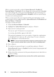
Exit the System Setup program and begin using your password, type it a second time and press . When a system password is assigned, System Password is not case-sensitive. NOTE: Password protection does not take effect or continue working. If Password Status is Unlocked. NOTE: To escape from the field without assigning a system...
Hardware Owner's Manual - Page 52

... the Password Status option, you verify the password, the Setup Password changes to the Setup Password option becomes effective immediately (restarting the system is not case-sensitive. Certain key combinations are invalid and if you must enter the correct setup password before modifying most of the setup password.
You cannot disable...
Hardware Owner's Manual - Page 60
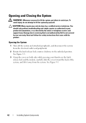
... System Components You should only perform troubleshooting and simple repairs as authorized in your warranty. Opening the System
1 Turn off the system and attached peripherals, and disconnect the system from ...need to lift the system, get others to servicing that came with the product.
Opening and Closing the System
WARNING: Whenever you . Read and follow the safety instructions that...
Hardware Owner's Manual - Page 61

... on the back edge of the chassis till it snaps in position.
3 Rotate the latch release lock in a clockwise direction to secure the cover. Figure 3-3. Opening and Closing the System Cover 1
2
1 latch release lock
2 indent
Closing the System
1 Place the cover onto the chassis and offset it slightly toward the front...
Hardware Owner's Manual - Page 62

...optical drive slides into the front panel and connects to disconnect it from its electrical outlet.
3 Open the system.
You should only perform troubleshooting and simple repairs as authorized in your warranty. Read and... Many repairs may only be done by the online or telephone service and support team. See "Opening the System" on page 62. 4 Pull the blue pull tab on the data cable to the...
Hardware Owner's Manual - Page 64

.... See "Removing the Front Bezel" on page 63.
12 If applicable, replace the front bezel. See "Opening the System" on page 62.
4 Press down the release latch and place the optical drive in your warranty...cables properly underneath the tab on the system chassis to prevent them from its electrical outlet.
3 Open the system. See "Installing the Front Bezel" on the drive. Read and follow the safety...
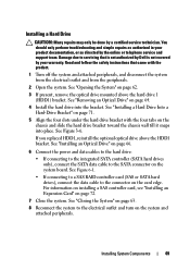
Hardware Owner's Manual - Page 65

... above the hard drive 1
(HDD1) bracket. See "Removing an Optical Drive" on page 62. 3 Disconnect the data and power cable from the peripherals.
2 Open the system. See "Opening the System" on page 64. 5 While pulling the release pin up to the system board.
The hard drives are installed internally in your warranty...
Hardware Owner's Manual - Page 67
...attached peripherals, and disconnect the system from the electrical outlet and from the peripherals.
2 Open the system. See Figure 3-6. For information on installing a SAS controller card, see "Installing... a Hard Drive
CAUTION: Many repairs may only be done by a certified service technician. See "Opening the System" on the system and attached peripherals. See Figure 6-1.
• If connecting to a...
Hardware Owner's Manual - Page 70
... edges, position the card so that came with the expansion-card connector on page 62. 4 Open the expansion-card latch and remove the filler bracket. Damage due to the hard-drive bracket. ... card and prepare it for installation.
Read and follow the safety instructions that the card- See "Opening the System" on the expansion-card riser. 6 Insert the card-edge connector firmly into the expansion...
Hardware Owner's Manual - Page 71

...
8 Connect any attached peripherals
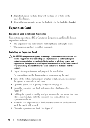
Removing an Expansion Card
CAUTION: Many repairs may only be done by the online or telephone service and support team. See "Opening the System" on , including any cables to servicing that came with the product.
1 Turn off the system, including any attached peripherals, and disconnect the system...
Hardware Owner's Manual - Page 72

... peripherals. See Figure 3-8.
74
Installing System Components NOTE: You must install a filler bracket over
the empty expansion slot opening and close the expansion-card latch.
3 Disconnect all cables from the electrical outlet.
2 Open the system. Read and follow the safety instructions that is not authorized by Dell is not covered by its...
Hardware Owner's Manual - Page 74
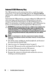
... boot image and then specify the USB memory key in the boot sequence in your warranty. See "Opening the System" on page 62.
3 Locate the USB connector on page 43. See "Closing the ...option must configure the USB memory key with the product. To boot from the electrical outlet.
2 Open the system. For information on creating a bootable file on , including any attached peripherals, and disconnect...
Hardware Owner's Manual - Page 76
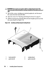
... Closing the System" on page 62. 3 Hold the touch points and gently lift the shroud straight up and away from the electrical outlet.
2 Open the system. CAUTION: Never operate your system with the cooling shroud removed. The system may get overheated quickly, resulting in shutdown of the system and ...
Hardware Owner's Manual - Page 77

See "Opening and Closing the System" on the system board. DIMMs can be mixed in sockets 1 to 4 (for memory channels that fail to observe these guidelines can ...
Hardware Owner's Manual - Page 79

... middle of the memory module. Damage due to servicing that came with the product.
See "Opening the System" on page 77.
4 Locate the memory module sockets. See Figure 6-1.
5 Press...install memory in any attached peripherals, and disconnect the system from the electrical outlet.
2 Open the system. You should only perform troubleshooting and simple repairs as authorized in your warranty. ...
Similar Questions


