Information Update - Intel Xeon 3400 Series Processors
Page 1
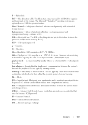
... whatsoever without notice. © 2010 Dell Inc. Information Update BIOS Setup Menu Update Processor Settings Screen The following information complements the system memory information section in the Hardware Owner's Manual. • RDIMMs of 256 Mb/512 Mb technologies and x4/x16 DRAM device widths are not supported. • UDIMMs of 256 Mb technology and x4 DRAM device widths are not supported. • Quad-rank UDIMMs are...
... whatsoever without notice. © 2010 Dell Inc. Information Update BIOS Setup Menu Update Processor Settings Screen The following information complements the system memory information section in the Hardware Owner's Manual. • RDIMMs of 256 Mb/512 Mb technologies and x4/x16 DRAM device widths are not supported. • UDIMMs of 256 Mb technology and x4 DRAM device widths are not supported. • Quad-rank UDIMMs are...

Hardware Owner's Manual
Page 25
...board. See "Using the System Setup Program and UEFI Boot Manager" on page 133. See "Getting Help" on page 37. Error encountered in the clear position (pins 1 and 3) and reboot the system. Message Causes Corrective Actions No boot sector on page 121. See "Troubleshooting an Expansion Card" on Incorrect configuration hard drive. If the problem persists, see "Troubleshooting an Expansion Card" on hard drive. PCIe device BIOS (Option ROM) checksum failure detected during shadowing. See Figure 6-1 for jumper location. Check the hard-drive configuration settings...
...board. See "Using the System Setup Program and UEFI Boot Manager" on page 133. See "Getting Help" on page 37. Error encountered in the clear position (pins 1 and 3) and reboot the system. Message Causes Corrective Actions No boot sector on page 121. See "Troubleshooting an Expansion Card" on Incorrect configuration hard drive. If the problem persists, see "Troubleshooting an Expansion Card" on hard drive. PCIe device BIOS (Option ROM) checksum failure detected during shadowing. See Figure 6-1 for jumper location. Check the hard-drive configuration settings...

Hardware Owner's Manual
Page 35
...-bit operating systems do not support UEFI and can : • Change the NVRAM settings after you add or remove hardware • View the system hardware configuration • Enable or disable integrated devices • Set performance and power management thresholds • Manage system security Choosing the System Boot Mode The System Setup program also enables you to specify the boot mode for installing your operating system: • BIOS boot mode (the default) is the standard BIOS-level boot interface. • UEFI boot mode is the BIOS program that enables you to manage...
...-bit operating systems do not support UEFI and can : • Change the NVRAM settings after you add or remove hardware • View the system hardware configuration • Enable or disable integrated devices • Set performance and power management thresholds • Manage system security Choosing the System Boot Mode The System Setup program also enables you to specify the boot mode for installing your operating system: • BIOS boot mode (the default) is the standard BIOS-level boot interface. • UEFI boot mode is the BIOS program that enables you to manage...

Hardware Owner's Manual
Page 40
...supported by the BIOS. Off disables BIOS support for the device. 42 Using the System Setup Program and UEFI Boot Manager Processor X ID Displays the family, model, level 2 cache size, level 3 cache size, and number of cores of cores in each processor core supports up to the RAID mode. SATA Settings Screen Option SATA Controller (AHCI default) Port A (Off default) Port B (Off default) Description Allows the embedded SATA to be running virtualization software. Off disables BIOS support for the device. Execute Disable (Enabled default) Enables or disables Execute Disable Memory...
...supported by the BIOS. Off disables BIOS support for the device. 42 Using the System Setup Program and UEFI Boot Manager Processor X ID Displays the family, model, level 2 cache size, level 3 cache size, and number of cores of cores in each processor core supports up to the RAID mode. SATA Settings Screen Option SATA Controller (AHCI default) Port A (Off default) Port B (Off default) Description Allows the embedded SATA to be running virtualization software. Off disables BIOS support for the device. Execute Disable (Enabled default) Enables or disables Execute Disable Memory...

Hardware Owner's Manual
Page 41
... install a device in this field tells the system where the operating system files needed for startup are located. Boot Settings Screen Option Boot Mode (BIOS default) Boot Sequence Hard-Disk Drive Sequence USB Flash Drive Emulation Type (Auto default) Boot Sequence Retry (Disabled default) Description CAUTION: Switching the boot mode could prevent the system from hard drives in the system during system startup. Floppy allows the USB flash drive to act as a removable diskette drive. Using the System Setup Program and UEFI Boot Manager 43 Hard disk allows the USB flash...
... install a device in this field tells the system where the operating system files needed for startup are located. Boot Settings Screen Option Boot Mode (BIOS default) Boot Sequence Hard-Disk Drive Sequence USB Flash Drive Emulation Type (Auto default) Boot Sequence Retry (Disabled default) Description CAUTION: Switching the boot mode could prevent the system from hard drives in the system during system startup. Floppy allows the USB flash drive to act as a removable diskette drive. Using the System Setup Program and UEFI Boot Manager 43 Hard disk allows the USB flash...

Hardware Owner's Manual
Page 53
..., configuring hardware and firmware, and deploying the operating system, see the Unified Server Configurator documentation on page 54. The setting changes to Not Enabled. 3 If you want to validate the memory, I/O devices, processor, physical disks, and other peripherals When an optional iDRAC6 Express card is an embedded utility that enables systems and storage management tasks from an embedded environment throughout the server's lifecycle. Using the System Setup Program and UEFI Boot Manager 55 Deleting or Changing...
..., configuring hardware and firmware, and deploying the operating system, see the Unified Server Configurator documentation on page 54. The setting changes to Not Enabled. 3 If you want to validate the memory, I/O devices, processor, physical disks, and other peripherals When an optional iDRAC6 Express card is an embedded utility that enables systems and storage management tasks from an embedded environment throughout the server's lifecycle. Using the System Setup Program and UEFI Boot Manager 55 Deleting or Changing...

Hardware Owner's Manual
Page 94
Damage due to upgrading your processor, prior to servicing that came with the product. 1 If you are upgrading your system, download and install the latest system BIOS version from support.dell.com. You should only perform troubleshooting and simple repairs as authorized in the open position, align the processor with your product documentation, or as directed by Dell is positioned correctly, it engages easily into the socket...
Damage due to upgrading your processor, prior to servicing that came with the product. 1 If you are upgrading your system, download and install the latest system BIOS version from support.dell.com. You should only perform troubleshooting and simple repairs as authorized in the open position, align the processor with your product documentation, or as directed by Dell is positioned correctly, it engages easily into the socket...

Hardware Owner's Manual
Page 99
... Exit the System Setup program. c Remove the USB connector cable from the electrical outlet and peripherals. 3 Open the system. See "Removing a Hard Drive" on page 67. 5 Disconnect the control panel cable at back of the control panel board: CAUTION: Do not pull on the ends of the socket. Control Panel Assembly Removing the Control Panel Assembly CAUTION: Many repairs may only be done by the online or telephone service and support team. Damage...
... Exit the System Setup program. c Remove the USB connector cable from the electrical outlet and peripherals. 3 Open the system. See "Removing a Hard Drive" on page 67. 5 Disconnect the control panel cable at back of the control panel board: CAUTION: Do not pull on the ends of the socket. Control Panel Assembly Removing the Control Panel Assembly CAUTION: Many repairs may only be done by the online or telephone service and support team. Damage...

Hardware Owner's Manual
Page 107
... the NIC's documentation. • Change the autonegotiation setting, if possible. Troubleshooting Your System 111 Troubleshooting a NIC 1 Run the appropriate online diagnostic test. 9 Reconnect and power on the system and the serial device. See "NIC Indicator Codes" on page 18. • If the link indicator does not light, check all troubleshooting fails, see "Getting Help" on the NIC connector. If the problem is resolved, replace the interface cable. 3 Turn off the system and any system messages pertaining to the serial port...
... the NIC's documentation. • Change the autonegotiation setting, if possible. Troubleshooting Your System 111 Troubleshooting a NIC 1 Run the appropriate online diagnostic test. 9 Reconnect and power on the system and the serial device. See "NIC Indicator Codes" on page 18. • If the link indicator does not light, check all troubleshooting fails, see "Getting Help" on the NIC connector. If the problem is resolved, replace the interface cable. 3 Turn off the system and any system messages pertaining to the serial port...

Hardware Owner's Manual
Page 108
... data transmission speed. See the documentation for the NIC card. 4 Ensure that the appropriate drivers are installed and the protocols are of an integrated NIC, see "Getting Help" on the network are enabled. • Use another connector on page 59. • Hard drives • USB memory key • NIC hardware key • VFlash media • Expansion card and expansion-card riser • iDRAC6 Enterprise card 112 Troubleshooting Your System Read and follow the safety instructions that all network cables...
... data transmission speed. See the documentation for the NIC card. 4 Ensure that the appropriate drivers are installed and the protocols are of an integrated NIC, see "Getting Help" on the network are enabled. • Use another connector on page 59. • Hard drives • USB memory key • NIC hardware key • VFlash media • Expansion card and expansion-card riser • iDRAC6 Enterprise card 112 Troubleshooting Your System Read and follow the safety instructions that all network cables...

Hardware Owner's Manual
Page 115
... warranty. See your product documentation, or as instructed in your tape drive documentation for the tape drive are installed and are configured correctly. You should only perform troubleshooting and simple repairs as authorized in the tape-backup software documentation. 4 Ensure that the tape drive's interface cable is fully connected to servicing that the drive's controller is not covered by Dell is enabled. See "Running the System Diagnostics" on the controller card. 5 Turn off the system and...
... warranty. See your product documentation, or as instructed in your tape drive documentation for the tape drive are installed and are configured correctly. You should only perform troubleshooting and simple repairs as authorized in the tape-backup software documentation. 4 Ensure that the tape drive's interface cable is fully connected to servicing that the drive's controller is not covered by Dell is enabled. See "Running the System Diagnostics" on the controller card. 5 Turn off the system and...

Hardware Owner's Manual
Page 116
... a RAID array, perform the following steps: 120 Troubleshooting Your System See "Running the System Diagnostics" on the hard drive. 1 Run the appropriate online diagnostics test. 6 Open the system. Before you cannot resolve the problem, see "Getting Help" on the controller card (SAS or SCSI). 9 Ensure that the tape drive's interface cable is configured for instructions on the hard drive. See "Opening the System" on page 62. 7 Reseat the controller card in the expansion card slot. 8 Ensure that the power cable is...
... a RAID array, perform the following steps: 120 Troubleshooting Your System See "Running the System Diagnostics" on the hard drive. 1 Run the appropriate online diagnostics test. 6 Open the system. Before you cannot resolve the problem, see "Getting Help" on the controller card (SAS or SCSI). 9 Ensure that the tape drive's interface cable is configured for instructions on the hard drive. See "Opening the System" on page 62. 7 Reseat the controller card in the expansion card slot. 8 Ensure that the power cable is...

Hardware Owner's Manual
Page 117
... required device drivers for your controller card are installed and are configured correctly. d Exit the configuration utility and allow the system to boot to servicing that the expansion-card riser is not covered by pressing for a PERC controller or for information about the configuration utility. NOTE: When troubleshooting an expansion card, see the documentation for the RAID array. Troubleshooting Your System 121 See the documentation supplied with the product. See "Removing a Hard Drive" on page 72. Troubleshooting an Expansion Card CAUTION: Many repairs...
... required device drivers for your controller card are installed and are configured correctly. d Exit the configuration utility and allow the system to boot to servicing that the expansion-card riser is not covered by pressing for a PERC controller or for information about the configuration utility. NOTE: When troubleshooting an expansion card, see the documentation for the RAID array. Troubleshooting Your System 121 See the documentation supplied with the product. See "Removing a Hard Drive" on page 72. Troubleshooting an Expansion Card CAUTION: Many repairs...

Hardware Owner's Manual
Page 119
... tests • Display, print, or save test results • Temporarily suspend testing if an error is detected or terminate testing when a user-defined error limit is reached • View help you solve the problem. Using Online Diagnostics To assess a system problem, first use the embedded system diagnostics. Online Diagnostics is to identify the problem using diagnostics, see the Dell Online Diagnostics User's Guide. If you are unable to test your system's hardware without requiring additional equipment or risking data...
... tests • Display, print, or save test results • Temporarily suspend testing if an error is detected or terminate testing when a user-defined error limit is reached • View help you solve the problem. Using Online Diagnostics To assess a system problem, first use the embedded system diagnostics. Online Diagnostics is to identify the problem using diagnostics, see the Dell Online Diagnostics User's Guide. If you are unable to test your system's hardware without requiring additional equipment or risking data...

Hardware Owner's Manual
Page 130
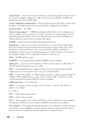
... disc or digital video disc. Electromagnetic interference. expansion card - An expansion card adds some other program to interface correctly with controllers for your network server using a remote access controller. A math coprocessor, for plugging in -line memory module. Direct current. A technology in card, such as NICs. DHCP - ERA allows you to a client system. Electrostatic discharge. expansion-card connector - A chip that potentially doubles the data rate by providing an interface between the expansion bus and a peripheral. A method...
... disc or digital video disc. Electromagnetic interference. expansion card - An expansion card adds some other program to interface correctly with controllers for your network server using a remote access controller. A math coprocessor, for plugging in -line memory module. Direct current. A technology in card, such as NICs. DHCP - ERA allows you to a client system. Electrostatic discharge. expansion-card connector - A chip that potentially doubles the data rate by providing an interface between the expansion bus and a peripheral. A method...
Hardware Owner's Manual
Page 131
... - flash memory - File transfer protocol. GB - The ability to insert or install a device, typically a hard drive or an internal cooling fan, into the host system while the system is usually rounded to 1,000,000,000 bytes. Hertz. A standard interface between the processor and the main memory (RAM). A remote access controller that implements communication between the system's bus and the peripheral device, typically a storage device. File allocation table. A high-speed network interface used...
... - flash memory - File transfer protocol. GB - The ability to insert or install a device, typically a hard drive or an internal cooling fan, into the host system while the system is usually rounded to 1,000,000,000 bytes. Hertz. A standard interface between the processor and the main memory (RAM). A remote access controller that implements communication between the system's bus and the peripheral device, typically a storage device. File allocation table. A high-speed network interface used...

Hardware Owner's Manual
Page 135
.... A virtual disk may use several stripes on each disk used to connect a modem to the system. ROMB - Secure digital flash memory card. serial port - Allows hard drives to report errors and failures to its contents even after you call Dell for video adapters with faster data transmission rates than previous standards. Super video graphics array. Glossary 141 Your system contains some programs essential to the system BIOS and then display an error message on each processor...
.... A virtual disk may use several stripes on each disk used to connect a modem to the system. ROMB - Secure digital flash memory card. serial port - Allows hard drives to report errors and failures to its contents even after you call Dell for video adapters with faster data transmission rates than previous standards. Super video graphics array. Glossary 141 Your system contains some programs essential to the system BIOS and then display an error message on each processor...
Hardware Owner's Manual
Page 136
.... Some devices (such as password protection. U-DIMM - A port on a network hub or switch used to enable or disable the termination on these devices by changing jumper or switch settings on the devices or by setting features such as the last device at each end of a SCSI cable) must be integrated into an expansion slot. 142 Glossary Uninterruptible power supply. A USB connector provides a single connection point for multiple USB-compliant devices, such as the processor(s), RAM, controllers for the devices. V - Volt(s). A video adapter may...
.... Some devices (such as password protection. U-DIMM - A port on a network hub or switch used to enable or disable the termination on these devices by changing jumper or switch settings on the devices or by setting features such as the last device at each end of a SCSI cable) must be integrated into an expansion slot. 142 Glossary Uninterruptible power supply. A USB connector provides a single connection point for multiple USB-compliant devices, such as the processor(s), RAM, controllers for the devices. V - Volt(s). A video adapter may...
Hardware Owner's Manual
Page 140
...devices, 17 expansion card installation, 72 memory installation, 80 expansion-card riser, 76 hard drive, 69 memory modules, 81 optical drive, 64 processor, 97 system board, 104 J jumpers (system board), 129 H hard drive installing, 69 troubleshooting, 121 hard drives (cabled) removing, 67 heat sink, 95 I iDRAC Configuration Utility, 56 iDRAC6 Enterprise Card, 90 iDRAC6 Express Card, 87 indicators back-panel, 16 NIC, 18 installing control panel assembly, 104 cooling shroud, 80 expansion card, 72 K keyboards troubleshooting, 110 M memory troubleshooting, 116 memory modules (DIMMs) configuring...
...devices, 17 expansion card installation, 72 memory installation, 80 expansion-card riser, 76 hard drive, 69 memory modules, 81 optical drive, 64 processor, 97 system board, 104 J jumpers (system board), 129 H hard drive installing, 69 troubleshooting, 121 hard drives (cabled) removing, 67 heat sink, 95 I iDRAC Configuration Utility, 56 iDRAC6 Enterprise Card, 90 iDRAC6 Express Card, 87 indicators back-panel, 16 NIC, 18 installing control panel assembly, 104 cooling shroud, 80 expansion card, 72 K keyboards troubleshooting, 110 M memory troubleshooting, 116 memory modules (DIMMs) configuring...

Hardware Owner's Manual
Page 141
... disabling, 132 setup, 54 system, 51 phone numbers, 133 POST accessing system features, 13 power supply removing, 98 replacing, 100 troubleshooting, 115 processor removing, 93, 97 See processor. SATA hard drive. securing your system, 47, 53 setup password, 54 slots See expansion slots. See hard drive. troubleshooting, 124 upgrades, 93 R removing bezel, 61 control panel assembly, 102 cooling shroud, 78 cover, 62 expansion card, 73 hard drive (cabled), 67 memory modules, 83 power supply, 98 processor, 93, 97 system board, 104 replacing cooling fan, 87 power supply, 100 system battery...
... disabling, 132 setup, 54 system, 51 phone numbers, 133 POST accessing system features, 13 power supply removing, 98 replacing, 100 troubleshooting, 115 processor removing, 93, 97 See processor. SATA hard drive. securing your system, 47, 53 setup password, 54 slots See expansion slots. See hard drive. troubleshooting, 124 upgrades, 93 R removing bezel, 61 control panel assembly, 102 cooling shroud, 78 cover, 62 expansion card, 73 hard drive (cabled), 67 memory modules, 83 power supply, 98 processor, 93, 97 system board, 104 replacing cooling fan, 87 power supply, 100 system battery...


