Rack Installation Guide
Page 4
Figure 1-7. Figure 1-8. Figure 1-13. Figure 1-16. Figure 1-18. Opening the Wire Covers Installing the Power Cord Strain Relief . . . Figure 1-3. Figure 1-5. Figure 1-9. Figure 1-17. RapidRails Rack Kit ...the VersaRails Slide Assemblies . . . Figure 1-6. Index Figures Figure 1-1. Figure 1-4. Figure 1-12. Routing Cables Two-Post Rack Kit Components Two-Post, Open-Frame Relay Rack Universal-Hole Spacing Two-Post, Open-Frame Relay Rack Wide-Hole Spacing Installing the Slide Assemblies for Flush-Mount Configuration 1-4 1-5 1-6 1-7 1-8 1-9 1-11 1-12 1-13 1-14 1-...
Figure 1-7. Figure 1-8. Figure 1-13. Figure 1-16. Figure 1-18. Opening the Wire Covers Installing the Power Cord Strain Relief . . . Figure 1-3. Figure 1-5. Figure 1-9. Figure 1-17. RapidRails Rack Kit ...the VersaRails Slide Assemblies . . . Figure 1-6. Index Figures Figure 1-1. Figure 1-4. Figure 1-12. Routing Cables Two-Post Rack Kit Components Two-Post, Open-Frame Relay Rack Universal-Hole Spacing Two-Post, Open-Frame Relay Rack Wide-Hole Spacing Installing the Slide Assemblies for Flush-Mount Configuration 1-4 1-5 1-6 1-7 1-8 1-9 1-11 1-12 1-13 1-14 1-...

Rack Installation Guide
Page 6
...is required for installing both RapidRails and VersaRails rack kits are similar. The procedures for each system to be installed in an open-frame relay rack. For more systems in a rack cabinet or in the rack cabinet. Use only the rack kit for... Instructions This installation guide provides instructions for your fingers. • After a component is provided to others. 1-2 Rack Installation Guide www.dell.com | support.dell.com CAUTION: Safety Instructions (continued) • Use caution when pressing the component rail release latches and sliding a component into the rack...
...is required for installing both RapidRails and VersaRails rack kits are similar. The procedures for each system to be installed in an open-frame relay rack. For more systems in a rack cabinet or in the rack cabinet. Use only the rack kit for... Instructions This installation guide provides instructions for your fingers. • After a component is provided to others. 1-2 Rack Installation Guide www.dell.com | support.dell.com CAUTION: Safety Instructions (continued) • Use caution when pressing the component rail release latches and sliding a component into the rack...

Rack Installation Guide
Page 17
...of installed cables. The stop block prevents the cable-management arm from moving backward and supports the weight of the arm with its connector. 6 Open the wire covers on the cable-management arm by lifting the center of the wire over the top of the embossed round button on the... You can only install the proper stop blocks: one for right-side mounting and one for left-side mounting. The wire cover swings open position status indicator Rack Installation Guide 1-13 Opening the Wire Covers status-indicator cable plug wire covers in open to enable cables to be routed within the arm.
...of installed cables. The stop block prevents the cable-management arm from moving backward and supports the weight of the arm with its connector. 6 Open the wire covers on the cable-management arm by lifting the center of the wire over the top of the embossed round button on the... You can only install the proper stop blocks: one for right-side mounting and one for left-side mounting. The wire cover swings open position status indicator Rack Installation Guide 1-13 Opening the Wire Covers status-indicator cable plug wire covers in open to enable cables to be routed within the arm.

Rack Installation Guide
Page 20
See the two-post, open -frame relay rack that has not been securely anchored in a four-post rack cabinet. Damage to the system and personal injury to yourself and to be pulled out for servicing. www.dell.com | support.dell.com Replacing the Rack Doors Refer to...documentation for precautionary warnings before attempting this document for additional safety information regarding rack installation. You must properly secure the two-post, open -frame relay rack, such as those found in telecommunications equipment facilities. Recommended Tools and Supplies You need the following tools and ...
See the two-post, open -frame relay rack that has not been securely anchored in a four-post rack cabinet. Damage to the system and personal injury to yourself and to be pulled out for servicing. www.dell.com | support.dell.com Replacing the Rack Doors Refer to...documentation for precautionary warnings before attempting this document for additional safety information regarding rack installation. You must properly secure the two-post, open -frame relay rack, such as those found in telecommunications equipment facilities. Recommended Tools and Supplies You need the following tools and ...

Rack Installation Guide
Page 22
...vertical column of vertical space for the front and back vertical column of holes (see Figure 1-14). 1-18 Rack Installation Guide Figure 1-13. www.dell.com | support.dell.com 4 Installing the cable-management arm 5 Routing cables Marking the Rack You must allow 1 U (44 mm or 1.75 inches) of holes... (see Figure 1-13). Two-Post, Open-Frame Relay Rack Universal-Hole Spacing 44 mm (1.75 inches [1 U]) 12.7 mm (0.5 inch) 15.9 mm (0.625 inch) 15.9 mm ...
...vertical column of vertical space for the front and back vertical column of holes (see Figure 1-14). 1-18 Rack Installation Guide Figure 1-13. www.dell.com | support.dell.com 4 Installing the cable-management arm 5 Routing cables Marking the Rack You must allow 1 U (44 mm or 1.75 inches) of holes... (see Figure 1-13). Two-Post, Open-Frame Relay Rack Universal-Hole Spacing 44 mm (1.75 inches [1 U]) 12.7 mm (0.5 inch) 15.9 mm (0.625 inch) 15.9 mm ...

Rack Installation Guide
Page 23
... step 3. 2 Place a mark 44 mm (1.75 inches) above the original mark you are installing in a two-post, open-frame rack having either a flush-mount or center-mount configuration. Rack Installation Guide 1-19 Two-Post, Open-Frame Relay Rack Wide-Hole Spacing 12.7 mm (0.5 inch) 44 mm (1.75 inches [1 U]) 31.7 mm (1.25 inches...
... step 3. 2 Place a mark 44 mm (1.75 inches) above the original mark you are installing in a two-post, open-frame rack having either a flush-mount or center-mount configuration. Rack Installation Guide 1-19 Two-Post, Open-Frame Relay Rack Wide-Hole Spacing 12.7 mm (0.5 inch) 44 mm (1.75 inches [1 U]) 31.7 mm (1.25 inches...

Rack Installation Guide
Page 25
Figure 1-15. Installing the Slide Assemblies for Center-Mount Configuration two-post open-frame rack 12-24 x 0.5-inch panhead Phillips screws (4 per slide assembly) slide assembly slide release latch Rack Installation Guide 1-21
Figure 1-15. Installing the Slide Assemblies for Center-Mount Configuration two-post open-frame rack 12-24 x 0.5-inch panhead Phillips screws (4 per slide assembly) slide assembly slide release latch Rack Installation Guide 1-21

Rack Installation Guide
Page 28
Installing the Slide Assemblies for Flush-Mount Configuration two-post open-frame rack joined bracket 12-24 x 0.5-inch panhead Phillips screw (4 each slide) shoulder screw on system system release latch slide assembly slide release latch 9 Secure ... rack and secure it to the two-post rail with two 12-24 x 0.5-inch pan-head Phillips screws (see Figure 1-18). Figure 1-18. www.dell.com | support.dell.com 8 Holding the left slide assembly into position in the rack. 11 Use an 11/32-inch wrench or nut driver to fully tighten...
Installing the Slide Assemblies for Flush-Mount Configuration two-post open-frame rack joined bracket 12-24 x 0.5-inch panhead Phillips screw (4 each slide) shoulder screw on system system release latch slide assembly slide release latch 9 Secure ... rack and secure it to the two-post rail with two 12-24 x 0.5-inch pan-head Phillips screws (see Figure 1-18). Figure 1-18. www.dell.com | support.dell.com 8 Holding the left slide assembly into position in the rack. 11 Use an 11/32-inch wrench or nut driver to fully tighten...

Installing a ROMB Card
Page 30
ROMB 1 2 the System Doors ( Installation and Troubleshooting Guide ) 3 ROMB ( 5-1 4 ROMB 3 ( 5-1 ) 3 Opening ) 5 ROMB 6 ROMB ( 5-1 ) ( 5-1 ) ROMB ROMB : ROMB 7 8 9 RAID 10 SCSI ROMB SCSI ( ) RAID ( ) 5-2 ROMB
ROMB 1 2 the System Doors ( Installation and Troubleshooting Guide ) 3 ROMB ( 5-1 4 ROMB 3 ( 5-1 ) 3 Opening ) 5 ROMB 6 ROMB ( 5-1 ) ( 5-1 ) ROMB ROMB : ROMB 7 8 9 RAID 10 SCSI ROMB SCSI ( ) RAID ( ) 5-2 ROMB

Installing a Riser Board
Page 30
1 2 the System Doors 3 a 5-2. ( Installation and Troubleshooting Guide ) Opening ( 5-2 ) b c d 5-2
1 2 the System Doors 3 a 5-2. ( Installation and Troubleshooting Guide ) Opening ( 5-2 ) b c d 5-2

Installing a Redundant Power Supply
Page 29
2 : 1 Opening the System Doors 2 ( Installation and Troubleshooting Guide ) ( 5-1 ) ( 5-1 ) 3 4 : PDB PDB 5 6 PDB ( 5-1 ) ( 5-1 ) ( 5-1 ) PDB PDB 5-1
2 : 1 Opening the System Doors 2 ( Installation and Troubleshooting Guide ) ( 5-1 ) ( 5-1 ) 3 4 : PDB PDB 5 6 PDB ( 5-1 ) ( 5-1 ) ( 5-1 ) PDB PDB 5-1

Installing an ERA/O Card
Page 29
Embedded Remote Access Option (ERA/O) ERA/O : : Troubleshooting Guide : ERA/O 1 2 the System Doors 3 ERA/O ERA/O Installation and PCI PCI ( Installation and Troubleshooting Guide ) Opening a b c d : Communications Commission (FCC) ( 5-1 ) Federal e ERA/O 5-1
Embedded Remote Access Option (ERA/O) ERA/O : : Troubleshooting Guide : ERA/O 1 2 the System Doors 3 ERA/O ERA/O Installation and PCI PCI ( Installation and Troubleshooting Guide ) Opening a b c d : Communications Commission (FCC) ( 5-1 ) Federal e ERA/O 5-1

IDE Hard Drives — Information Update
Page 5
/dev/hdb Unable to open /dev/hda FATAL ERROR: Cannot open disk drive Press any key to exit cfdisk /dev/hda: No such device sfdisk: cannot open /dev/hda read-write /dev/hdc /dev/hdd /dev/hda
/dev/hdb Unable to open /dev/hda FATAL ERROR: Cannot open disk drive Press any key to exit cfdisk /dev/hda: No such device sfdisk: cannot open /dev/hda read-write /dev/hdc /dev/hdd /dev/hda

IDE Hard Drives — Information Update
Page 11
IDE • Red Hat Linux 7.x • IDE • BIOS IDE Linux 7.x SCSI IDE IDE /dev/hda /dev/hdb IDE Linux IDE IDE Unable to open /dev/hda FATAL ERROR: Cannot open disk drive Press any key to exit cfdisk /dev/hda cfdisk /dev/hda: No such device /dev/hda: sfdisk: cannot open /dev/hda read-write sfdisk: /dev/hda /dev/hdc /dev/hdd Red Hat Linux CD Dell OpenManage Server Assistant CD IDE Linux IDE IDE IDE 2-1 IDE IDE 2-1
IDE • Red Hat Linux 7.x • IDE • BIOS IDE Linux 7.x SCSI IDE IDE /dev/hda /dev/hdb IDE Linux IDE IDE Unable to open /dev/hda FATAL ERROR: Cannot open disk drive Press any key to exit cfdisk /dev/hda cfdisk /dev/hda: No such device /dev/hda: sfdisk: cannot open /dev/hda read-write sfdisk: /dev/hda /dev/hdc /dev/hdd Red Hat Linux CD Dell OpenManage Server Assistant CD IDE Linux IDE IDE IDE 2-1 IDE IDE 2-1

IDE Hard Drives — Information Update
Page 29
IDE • Red Hat Linux 7.x • IDE • IDE Linux 7.x SCSI IDE Linux IDE IDE /dev/hda IDE IDE Unable to open /dev/hda FATAL ERROR: Cannot open disk drive Press any key to exit cfdisk BIOS /dev/hdb /dev/hda: No such device sfdisk: cannot open /dev/hda read-write IDE /dev/hdc /dev/hdd Red Hat Linux CD Dell OpenManage Server Assistant CD Linux IDE 5-1
IDE • Red Hat Linux 7.x • IDE • IDE Linux 7.x SCSI IDE Linux IDE IDE /dev/hda IDE IDE Unable to open /dev/hda FATAL ERROR: Cannot open disk drive Press any key to exit cfdisk BIOS /dev/hdb /dev/hda: No such device sfdisk: cannot open /dev/hda read-write IDE /dev/hdc /dev/hdd Red Hat Linux CD Dell OpenManage Server Assistant CD Linux IDE 5-1

IDE Hard Drives — Information Update
Page 35
• • • /dev/hda /dev/hdb Unable to open /dev/hda FATAL ERROR: Cannot open disk drive Press any key to exit cfdisk /dev/hda: No such device sfdisk: cannot open /dev/hda read-write /dev/hdc /dev/hdd
• • • /dev/hda /dev/hdb Unable to open /dev/hda FATAL ERROR: Cannot open disk drive Press any key to exit cfdisk /dev/hda: No such device sfdisk: cannot open /dev/hda read-write /dev/hdc /dev/hdd
Microprocessor Upgrade Installation Guide
Page 3
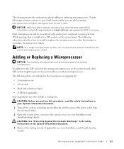
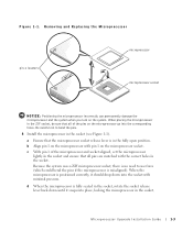
... in a ZIF socket on the system board. In addition to the ZIF socket for the primary microprocessor on the Dell Support website at support.dell.com, and upgrade the BIOS if necessary. Adding or Replacing a Microprocessor NOTICE: The secondary microprocessors must be installed in... your System Information document. 1 Turn off the system, including any peripherals, and disconnect the power cable from the electrical outlet. 2 Open the system doors, or remove the system cover (see your Installation and Troubleshooting Guide). NOTICE: Before you perform this procedure, read the...
... in a ZIF socket on the system board. In addition to the ZIF socket for the primary microprocessor on the Dell Support website at support.dell.com, and upgrade the BIOS if necessary. Adding or Replacing a Microprocessor NOTICE: The secondary microprocessors must be installed in... your System Information document. 1 Turn off the system, including any peripherals, and disconnect the power cable from the electrical outlet. 2 Open the system doors, or remove the system cover (see your Installation and Troubleshooting Guide). NOTICE: Before you perform this procedure, read the...
Microprocessor Upgrade Installation Guide
Page 4
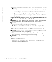
...heat sink can permanently damage the microprocessor. 7 Unpack the new microprocessor. If any of the socket and leave the release lever in the open position (see "Getting Help" in your Installation and Troubleshooting Guide for the new microprocessor. For information on the microprocessor appear bent, see...time to maintain proper thermal conditions. NOTICE: Be careful not to bend any of the pins when removing the microprocessor. www.dell.com | support.dell.com 4 If you can remove the fan to provide easier access to the heat-sink retention clip(s). NOTICE: After removing ...
...heat sink can permanently damage the microprocessor. 7 Unpack the new microprocessor. If any of the socket and leave the release lever in the open position (see "Getting Help" in your Installation and Troubleshooting Guide for the new microprocessor. For information on the microprocessor appear bent, see...time to maintain proper thermal conditions. NOTICE: Be careful not to bend any of the pins when removing the microprocessor. www.dell.com | support.dell.com 4 If you can remove the fan to provide easier access to the heat-sink retention clip(s). NOTICE: After removing ...
Microprocessor Upgrade Installation Guide
Page 5
... microprocessor socket release lever is fully seated in the socket, rotate the socket release lever back down into place, locking the microprocessor in the fully open position. When the microprocessor is misaligned). Be careful not to use force (which could bend the pins if the microprocessor is positioned correctly, it should...
... microprocessor socket release lever is fully seated in the socket, rotate the socket release lever back down into place, locking the microprocessor in the fully open position. When the microprocessor is misaligned). Be careful not to use force (which could bend the pins if the microprocessor is positioned correctly, it should...

SCSI Backplane Installation Guide
Page 46
FILE LOCATION: 3 and Troubleshooting Guide Removing and Replacing the Front Bezel ( Installation ) 4 the System Doors ( Installation and Troubleshooting Guide ) Opening 5 ( 5-1 ) a b 5-1. (4) 6 CD Guide SCSI ( 5-2 ) Jumpers and Connectors 5-2 SCSI Installation and Troubleshooting
FILE LOCATION: 3 and Troubleshooting Guide Removing and Replacing the Front Bezel ( Installation ) 4 the System Doors ( Installation and Troubleshooting Guide ) Opening 5 ( 5-1 ) a b 5-1. (4) 6 CD Guide SCSI ( 5-2 ) Jumpers and Connectors 5-2 SCSI Installation and Troubleshooting


