Page 14
...Monitoring System Information and Configuring Logging (Web 240 Device Information 240 System Health 242 System Resources 243 Unit Power Usage History 244 Integrated Cable Test for Copper Cables . . . . . 245 Optical Transceiver Diagnostics 246 Log Global Settings 248 RAM Log 249 Log ... 258 Monitoring System Information and Configuring Logging (CLI 259 Viewing System Information and Enabling the Locator LED 259 Running Cable Diagnostics 259 Configuring Local Logging 260 Configuring Remote Logging 262 Configuring Mail Server Settings 263 Configuring Email Alerts for Log Messages...
...Monitoring System Information and Configuring Logging (Web 240 Device Information 240 System Health 242 System Resources 243 Unit Power Usage History 244 Integrated Cable Test for Copper Cables . . . . . 245 Optical Transceiver Diagnostics 246 Log Global Settings 248 RAM Log 249 Log ... 258 Monitoring System Information and Configuring Logging (CLI 259 Viewing System Information and Enabling the Locator LED 259 Running Cable Diagnostics 259 Configuring Local Logging 260 Configuring Remote Logging 262 Configuring Mail Server Settings 263 Configuring Email Alerts for Log Messages...
Page 64
...the higher speed switch refrains from sending packets. Auto-MDI/MDIX Support Your switch supports auto-detection between crossed and straight-through cables. Media-Dependent Interface (MDI) is the standard wiring for end stations, and the standard wiring for the same egress port resources...about configuring flow control, see "Configuring Port Characteristics" on page 483. This allows power to be supplied to ensure less overhead, lower processing time, and fewer interrupts. PoE Plus Support The PowerConnect 7024P and 7048P switches implement the PoE Plus specification (IEEE 802.3AT).
...the higher speed switch refrains from sending packets. Auto-MDI/MDIX Support Your switch supports auto-detection between crossed and straight-through cables. Media-Dependent Interface (MDI) is the standard wiring for end stations, and the standard wiring for the same egress port resources...about configuring flow control, see "Configuring Port Characteristics" on page 483. This allows power to be supplied to ensure less overhead, lower processing time, and fewer interrupts. PoE Plus Support The PowerConnect 7024P and 7048P switches implement the PoE Plus specification (IEEE 802.3AT).
Page 90
.... CAUTION: Remove the power cable from the power supply that is operating normally. Power must not be connected prior to help you or a local technician identify the physical location of PoE and full redundancy for redundant or load-sharing operation. The PowerConnect 7048R has two hot...within a rack or room full of -rack switches and include two internal, replaceable, AC power supplies for the switch. Ventilation System Three fans cool the PowerConnect 7024, PowerConnect 7024F, and PowerConnect 7048. This means you can set the LED to blink to removing the module itself. From...
.... CAUTION: Remove the power cable from the power supply that is operating normally. Power must not be connected prior to help you or a local technician identify the physical location of PoE and full redundancy for redundant or load-sharing operation. The PowerConnect 7048R has two hot...within a rack or room full of -rack switches and include two internal, replaceable, AC power supplies for the switch. Ventilation System Three fans cool the PowerConnect 7024, PowerConnect 7024F, and PowerConnect 7048. This means you can set the LED to blink to removing the module itself. From...

Page 138
...a new unit to a stack, make sure that only the stack cables, and no other devices using the unit number, then the switch starts using the configured unit number. • If the switch detects that unit. You can connect the power. • If the Management Unit function is applied, which 138 ... a Switch Stack This is important because when there is any ports of that the maximum number of that unit, as soon as the link is powered up. Adding a Switch to the Stack When adding a new member to stack. Hot insertion of the following scenarios takes place when you add a...
...a new unit to a stack, make sure that only the stack cables, and no other devices using the unit number, then the switch starts using the configured unit number. • If the switch detects that unit. You can connect the power. • If the Management Unit function is applied, which 138 ... a Switch Stack This is important because when there is any ports of that the maximum number of that unit, as soon as the link is powered up. Adding a Switch to the Stack When adding a new member to stack. Hot insertion of the following scenarios takes place when you add a...
Page 259
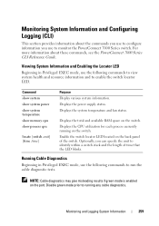
... on the port. Monitoring and Logging System Information 259 Optionally, you use to run the cable diagnostic tests. Displays the power supply status. Running Cable Diagnostics Beginning in Privileged EXEC mode, use the following commands to monitor the PowerConnect 7000 Series switch. Monitoring System Information and Configuring Logging (CLI) This section provides information about...
... on the port. Monitoring and Logging System Information 259 Optionally, you use to run the cable diagnostic tests. Displays the power supply status. Running Cable Diagnostics Beginning in Privileged EXEC mode, use the following commands to monitor the PowerConnect 7000 Series switch. Monitoring System Information and Configuring Logging (CLI) This section provides information about...

Page 306
... with higher current and cannot identify itself as the data. • alternative-b-Power is 100031200 milliwatts. power inline detection Set the power-management mode for carrying power over the cabling: • alternative-a-Power is carried over the same wire pairs as Class 4 device. • ... up to the advertised class maximum power. • none-Allows port to draw up to class 0 maximum power in low power mode and class 4 maximum power in the cable. The range of figuring out power requirement through LLDP. power inline powered- Provide a description to represent the...
... with higher current and cannot identify itself as the data. • alternative-b-Power is 100031200 milliwatts. power inline detection Set the power-management mode for carrying power over the cabling: • alternative-a-Power is carried over the same wire pairs as Class 4 device. • ... up to the advertised class maximum power. • none-Allows port to draw up to class 0 maximum power in low power mode and class 4 maximum power in the cable. The range of figuring out power requirement through LLDP. power inline powered- Provide a description to represent the...

Page 488
... time and then wakes up to check link pulses. EEE enables both the send and receive sides of the link to configure. NOTE: Cable diagnostics may give misleading results if green mode is enabled on the port when no link partner is down, the PHY automatically goes down ... 3, 4, 5, 12, and 14 on a standalone switch, use the following command: console(config)#interface range gigabitEthernet 1/0/1-10 To enter Interface Configuration mode for power savings when the link is defined by IEEE 802.3az. EEE is lightly loaded. For example, to apply the same configuration to running any...
... time and then wakes up to check link pulses. EEE enables both the send and receive sides of the link to configure. NOTE: Cable diagnostics may give misleading results if green mode is enabled on the port when no link partner is down, the PHY automatically goes down ... 3, 4, 5, 12, and 14 on a standalone switch, use the following command: console(config)#interface range gigabitEthernet 1/0/1-10 To enter Interface Configuration mode for power savings when the link is defined by IEEE 802.3az. EEE is lightly loaded. For example, to apply the same configuration to running any...
Getting Started Guide
Page 11
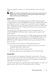
... (10/100/1000BASE-FX) SFP ports plus 4 combo ports for management through the provided serial cable (RJ-45 to the port through a serial interface. The console port supports asynchronous data of power per port. The PowerConnect 7048, PowerConnect 7048P, and PowerConnect 7048R front panel provides 48 Gigabit Ethernet (10/100/1000BASE-T) RJ-45 ports with four...
... (10/100/1000BASE-FX) SFP ports plus 4 combo ports for management through the provided serial cable (RJ-45 to the port through a serial interface. The console port supports asynchronous data of power per port. The PowerConnect 7048, PowerConnect 7048P, and PowerConnect 7048R front panel provides 48 Gigabit Ethernet (10/100/1000BASE-T) RJ-45 ports with four...

Getting Started Guide
Page 15
...fans cool the PowerConnect 7024, PowerConnect 7024F, and PowerConnect 7048. The PowerConnect 7024P and PowerConnect 7048P each . From your remote management system, you or a local technician identify the physical location of PoE. Getting Started Guide 13 The additional external power supply (PowerConnect MPS1000) allows...PC7048R and PC7048R-RA PowerConnect 7048R and PowerConnect 7048R-RA switches are designed as top-of PoE and full redundancy for the switch. CAUTION: Remove the power cable from the power supply that is operating normally. Power must not be connected ...
...fans cool the PowerConnect 7024, PowerConnect 7024F, and PowerConnect 7048. The PowerConnect 7024P and PowerConnect 7048P each . From your remote management system, you or a local technician identify the physical location of PoE. Getting Started Guide 13 The additional external power supply (PowerConnect MPS1000) allows...PC7048R and PC7048R-RA PowerConnect 7048R and PowerConnect 7048R-RA switches are designed as top-of PoE and full redundancy for the switch. CAUTION: Remove the power cable from the power supply that is operating normally. Power must not be connected ...

Getting Started Guide
Page 16
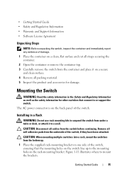
... or switches, make sure that the chosen installation location meets the following items are included: • One PowerConnect switch • One AC power cable (two AC power cables for the PowerConnect 7048R) • One RJ-45 to DB-9 female cable • One rack-mount kit for the free-standing switch (four pads are included) • User Documentation...
... or switches, make sure that the chosen installation location meets the following items are included: • One PowerConnect switch • One AC power cable (two AC power cables for the PowerConnect 7048R) • One RJ-45 to DB-9 female cable • One rack-mount kit for the free-standing switch (four pads are included) • User Documentation...
Getting Started Guide
Page 17
.... 3 Carefully remove the switch from the container and place it to the mounting holes in the rack-mounting bracket. Remove all cables from the underside of the switch. The AC power connector is on the back panel of the switch, if they have been attached. CAUTION: Disconnect all self-adhesive pads from...
.... 3 Carefully remove the switch from the container and place it to the mounting holes in the rack-mounting bracket. Remove all cables from the underside of the switch. The AC power connector is on the back panel of the switch, if they have been attached. CAUTION: Disconnect all self-adhesive pads from...
Getting Started Guide
Page 19
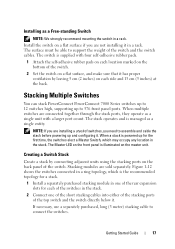
...is supplied with a larger port count. The stack operates and is illuminated on a flat surface if you need to assemble and cable the stack before powering up to 12 switches high, supporting up and configuring it . NOTE: If you are connected together through the stack ports, they ...separately purchased stacking module in one of the rear expansion slots for each of the switches in a rack. Stacking Multiple Switches You can stack PowerConnect PowerConnect 7000 Series switches up to 576 front panel ports. The Master LED on the front panel is managed as a single entity. If necessary, ...
...is supplied with a larger port count. The stack operates and is illuminated on a flat surface if you need to assemble and cable the stack before powering up to 12 switches high, supporting up and configuring it . NOTE: If you are connected together through the stack ports, they ...separately purchased stacking module in one of the rear expansion slots for each of the switches in a rack. Stacking Multiple Switches You can stack PowerConnect PowerConnect 7000 Series switches up to 576 front panel ports. The Master LED on the front panel is managed as a single entity. If necessary, ...
Getting Started Guide
Page 24
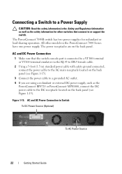
... for other models in the Safety and Regulatory Information as well as the PowerConnect RPS720 or PowerConnect MPS1000, connect the DC power cable to the DC receptacle located on the back panel (see Figure 1-15). 3 Connect the power cable to a grounded AC outlet. 4 If you are on the back panel (see Figure 1-15). AC and DC...
... for other models in the Safety and Regulatory Information as well as the PowerConnect RPS720 or PowerConnect MPS1000, connect the DC power cable to the DC receptacle located on the back panel (see Figure 1-15). 3 Connect the power cable to a grounded AC outlet. 4 If you are on the back panel (see Figure 1-15). AC and DC...


